2 stroke thread (with occasional F1 relevance!)

All that has to do with the power train, gearbox, clutch, fuels and lubricants, etc. Generally the mechanical side of Formula One.
manolis
manolis
107
Joined: 18 Mar 2014, 10:00

Re: 2 stroke thread (with occasional F1 relevance!)

Post

Hello all.

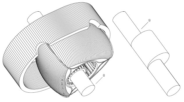
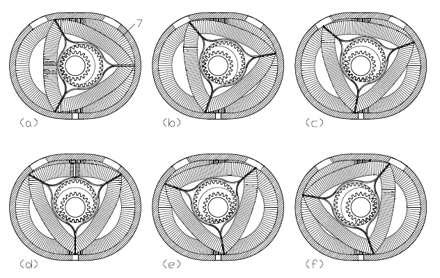
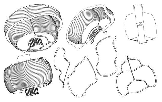
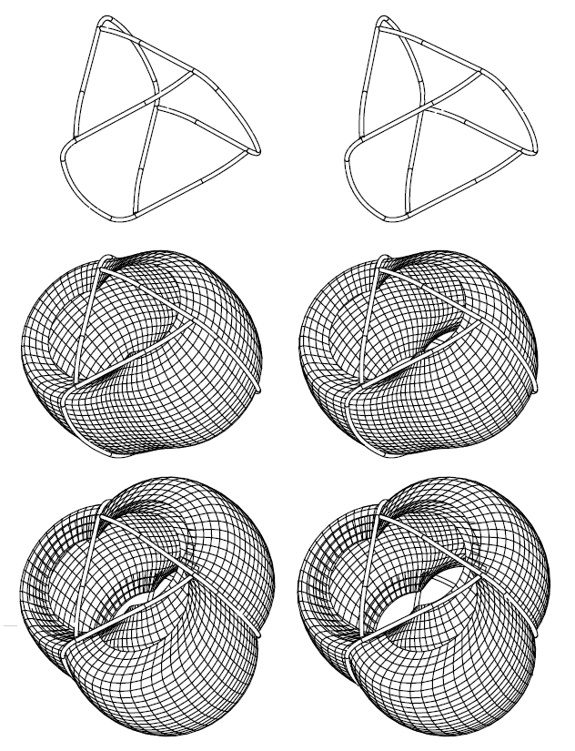
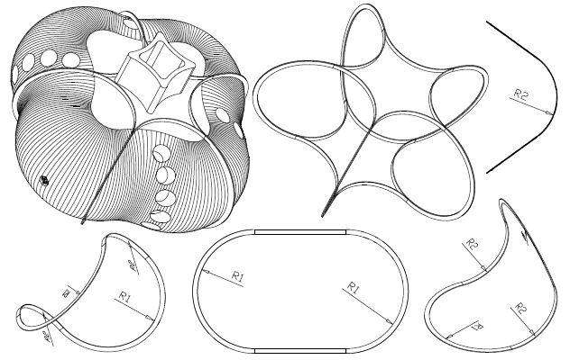
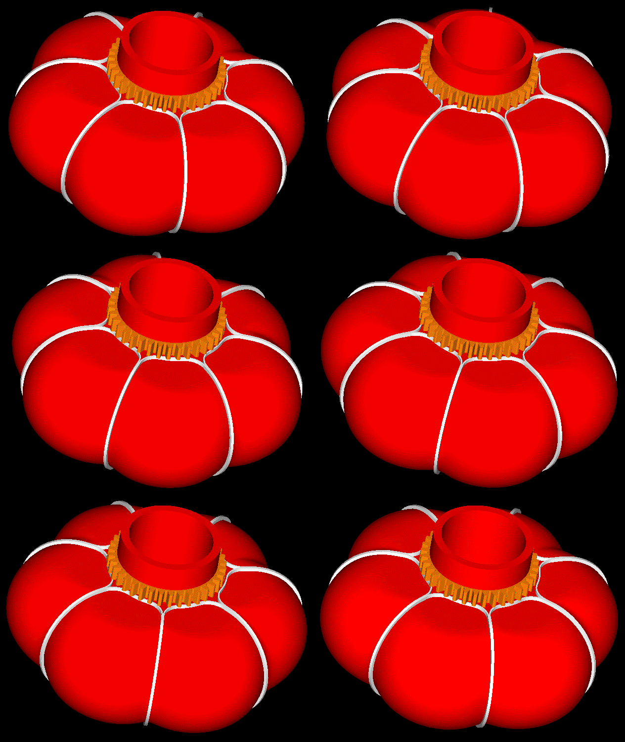
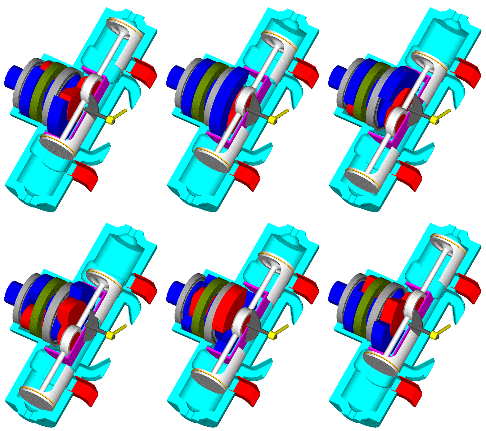
Here is a Wankel-like Rotary Engine:

Image

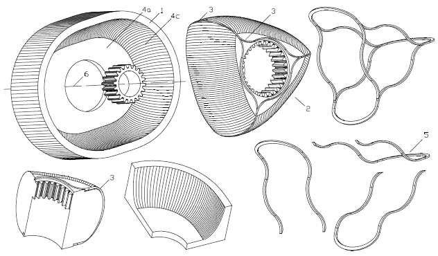
The working surface whereon the seals abut is not a “cylindrical” surface but a 3D curved surface ending smoothly / tangentially on the side flat surfaces of the casing.

Image

Image

Image

Image

The typical “Wankel sealing grid” (wherein each combustion chamber is sealed by a set of two side seals, two apex seals and four button (or corner) seals) can be replaced by a single piece seal per combustion chamber.


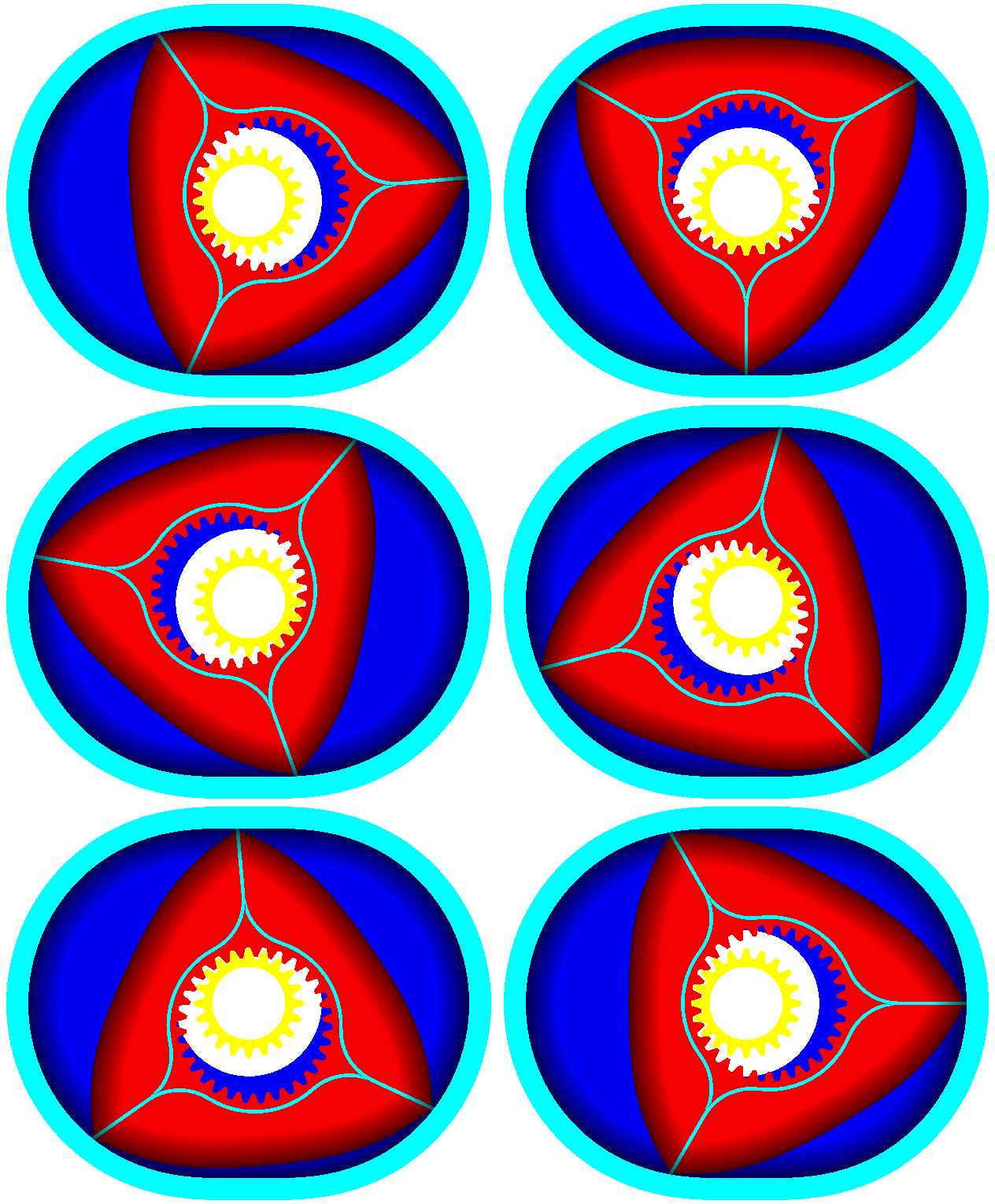
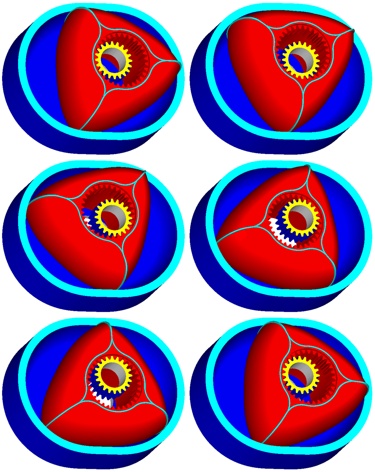
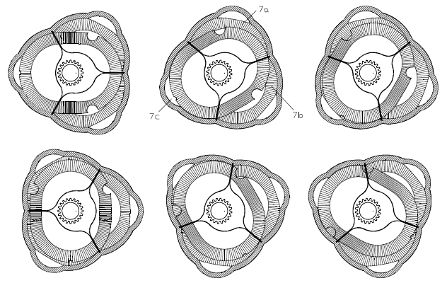
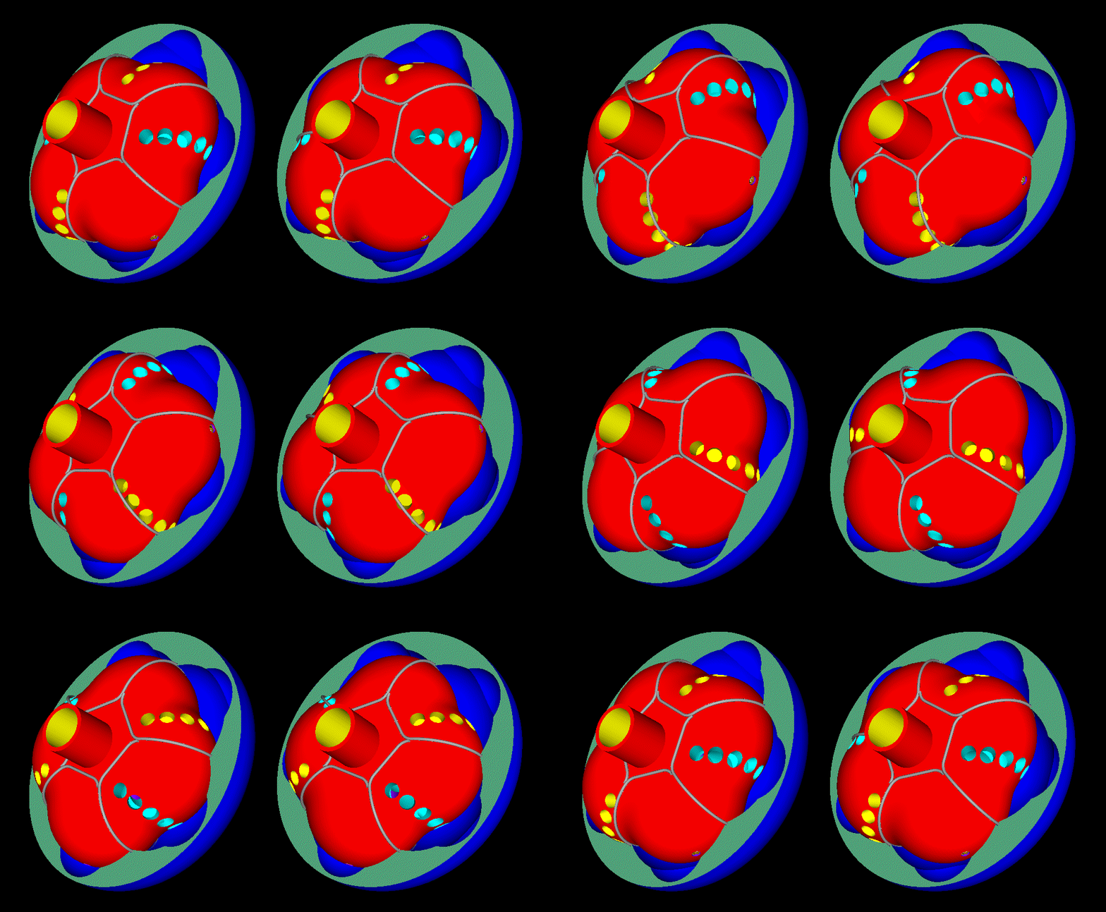
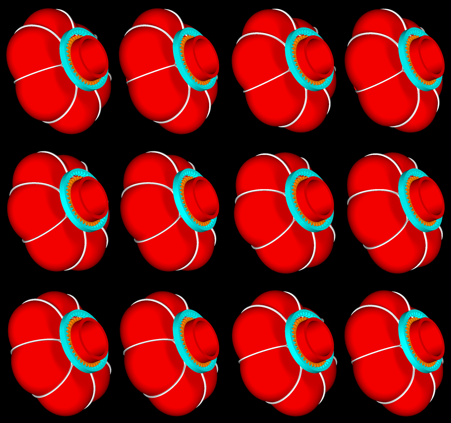
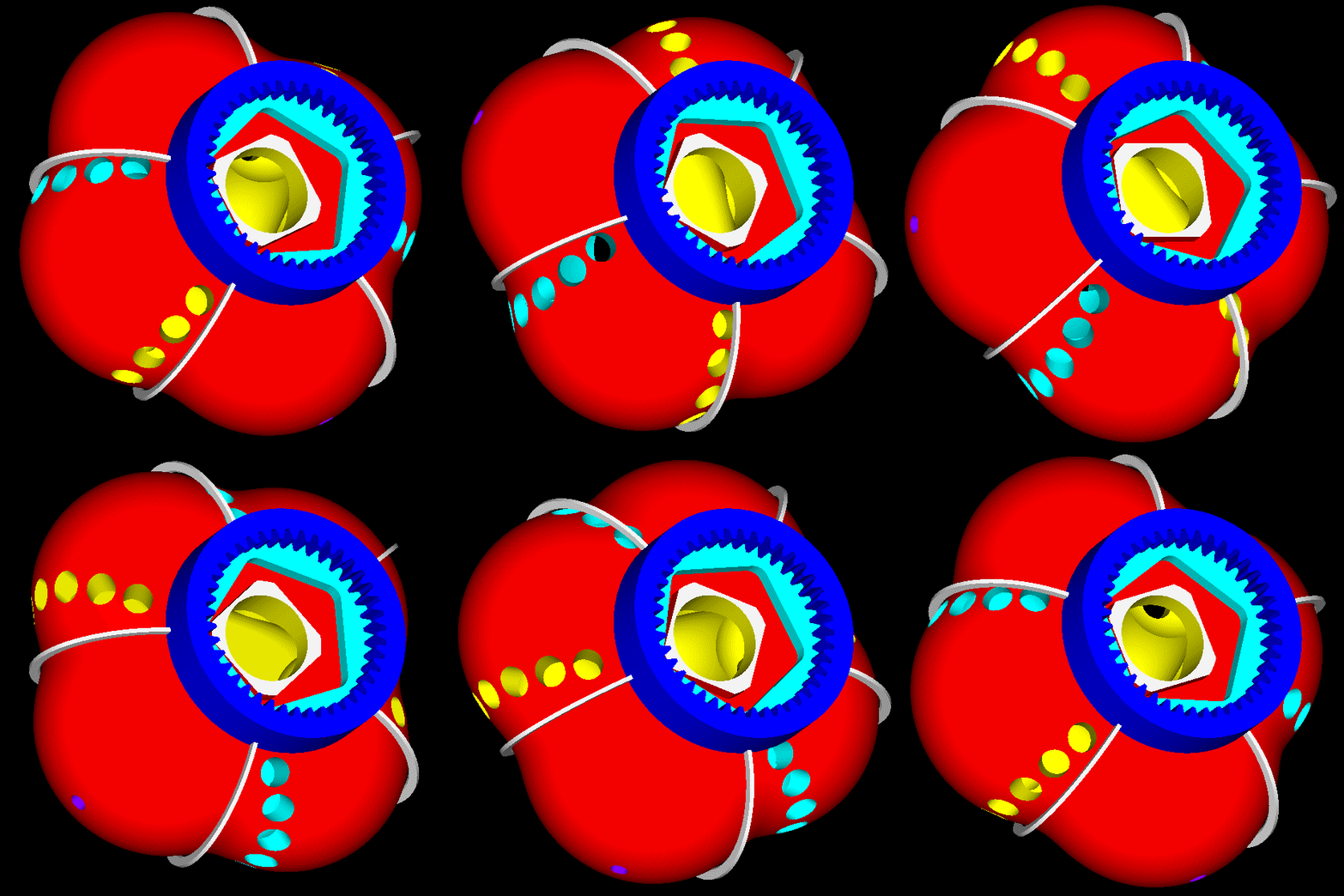
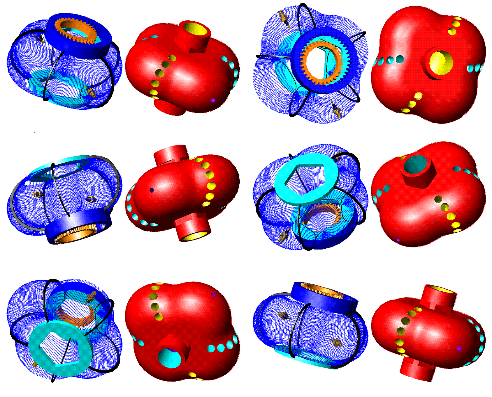
Here is a PatWankel wherein the working surface is on the inner body (say as in the Liquid Piston engine):

Image

Image

Image

Image

Image

One seal per combustion chamber, as in the reciprocating piston engines.


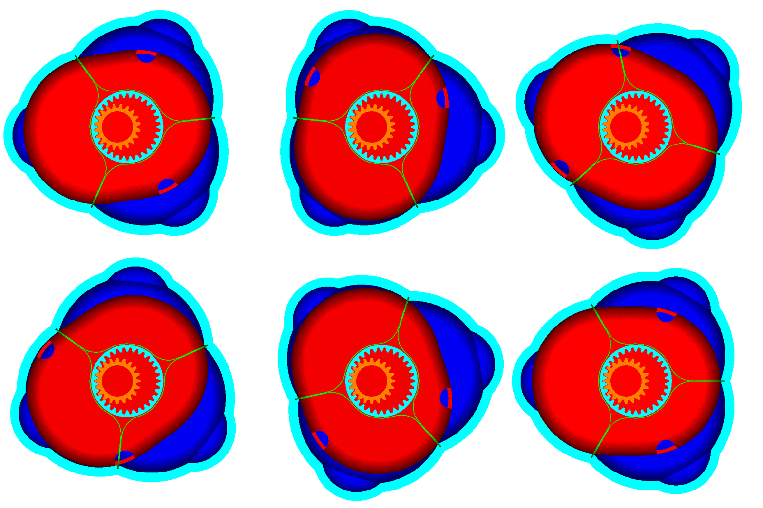
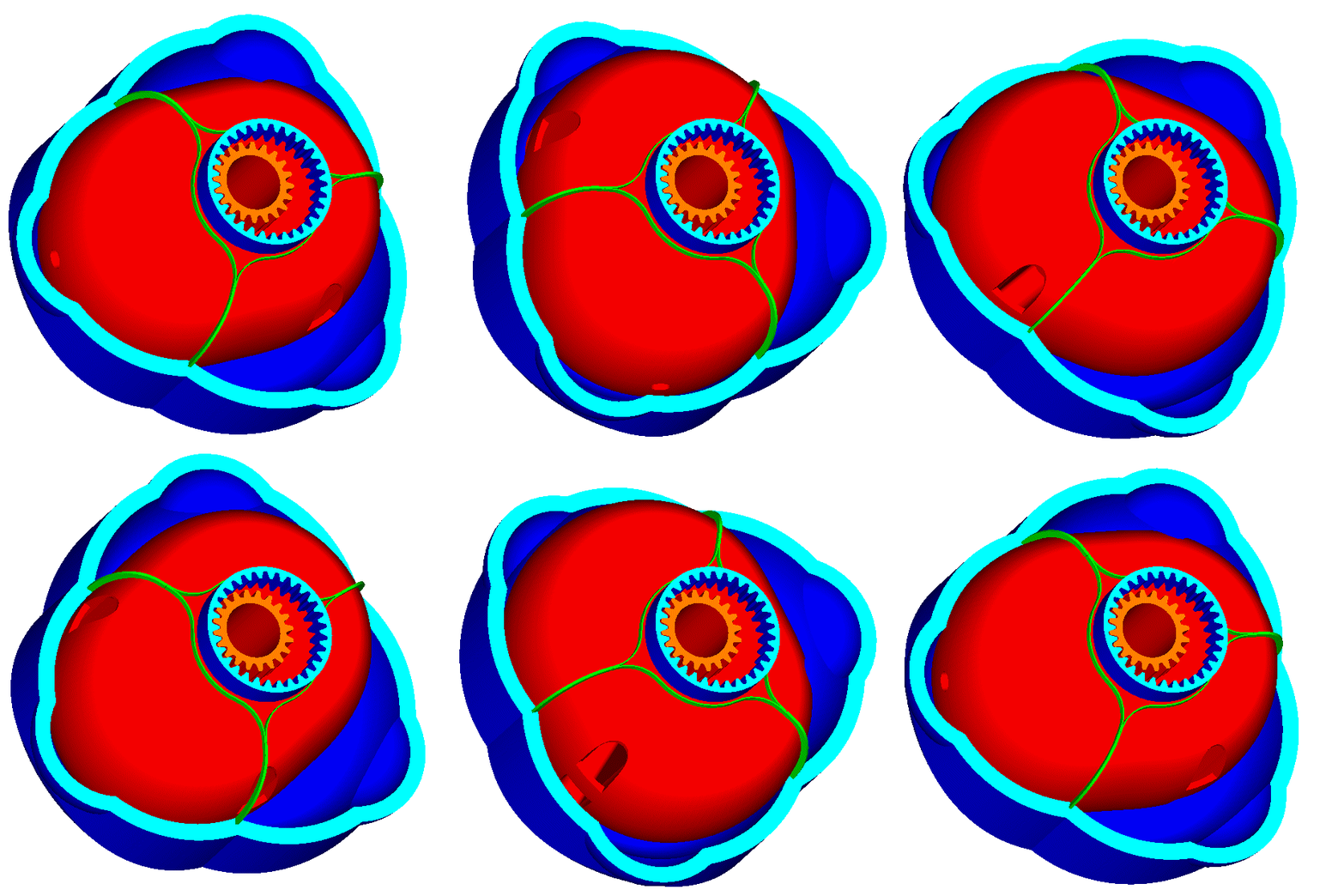
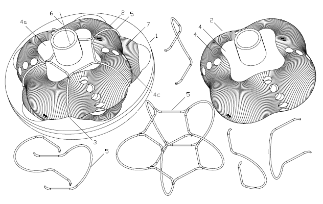
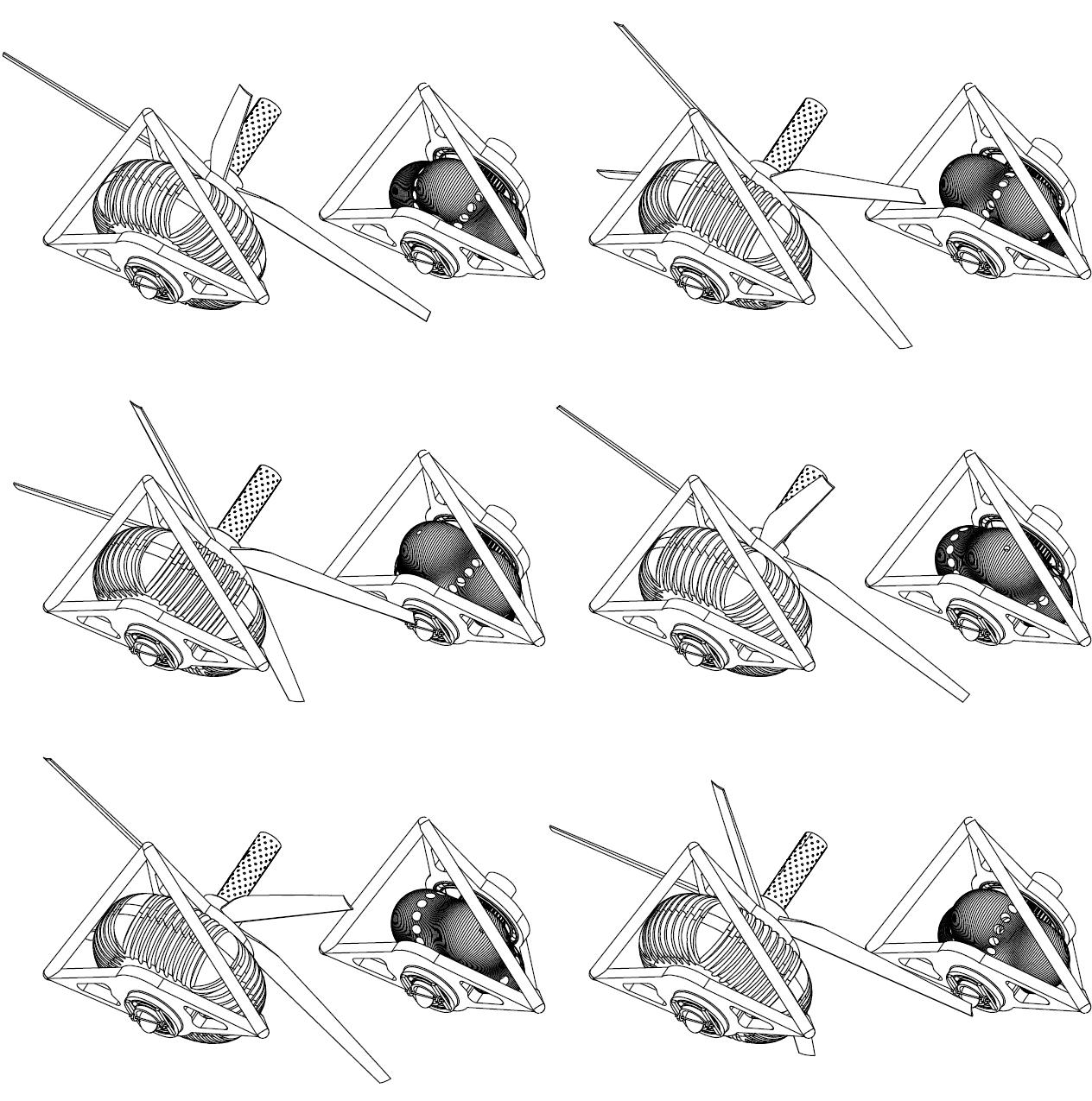
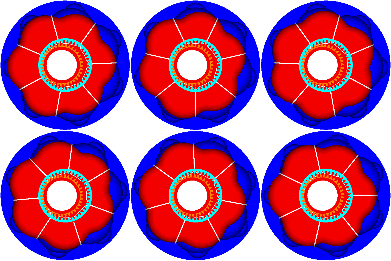
This five “cylinder” PatWankel rotary ( stereoscopic view, as at http://www.pattakon.com/pattakonStereoscopy.htm ) :

Image

has two combustions per rotation of the inner body, i.e. as much as a two-rotor Wankel Rotary (say, Mazda RX-8).

Image

Image

Image

Does the oval seal at bottom middle remind the Honda NR750?

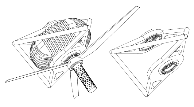
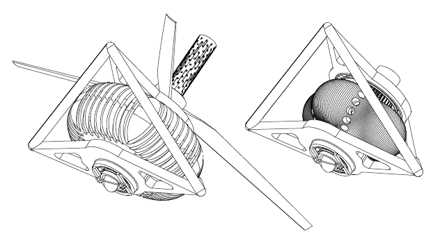
Imagine this PatWankel engine at the back of an airplane pushing forwards:

Image

Image

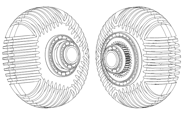
There is no eccentric shaft.
There are no balancing webs.
However it is perfectly balanced.


For more: http://www.pattakon.com/pattakonPatWankel.htm


Thoughts?

Objections?

Thanks
Manolis Pattakos

Muniix
Muniix
14
Joined: 29 Nov 2016, 13:29
Location: Sydney, Australia

Re: 2 stroke thread (with occasional F1 relevance!)

Post

J.A.W. wrote:FW17, I suggest you have a closer look... the Yamaha patent also includes provision for twin injectors,
which is current practice in 2T DI snowmobile usage, & I note also, that it is 4T engines that compete against
them which require the added cost/complexity of turbocharging to provide the needed boost in power output.

There are no current turbocharged production roadbikes since they do not have to compete with 2Ts..
& as for sports competition, 2Ts are either outright banned, or must be significantly restricted in capacity.

As for your opinions regarding N/A engines being "irrelevant", you might like to check the findings of emissions
research, which when done in 'real world' on road testing finds the harder worked small capacity turbocharged
engines to be worse offenders...

A situation which may well spell their demise - under changes mooted to ensure emissions reg's reflect actual
driving outputs - rather than laboratory test - procedures..
Several European cities are currently flagging a ban on entry to vehicles that cannot meet these requirements.
Hi back tracking a little to the Emissions/Efficiency [mechanical complexity not operating efficiency] I read operating when I see the word efficiency until I read the context, maybe establishing a convention to distinguish the two. Most published papers on DI or combustion refer to operating efficiency with that word. From what I have read it is just hard to get direct injection of multicomponent gasoline/petrol to combust cleanly even with high quality injectors at high pressures > 350 bar which consumes excess energy, in an attempt to reduce PM complicated by the three way cat's need to run at close to stoic. eliminating the use of ultra-lean to reduce NOx's, lower temperature combustion is mutually exclusing to the twc. The system appears a bit broken compared with TJI with DI of LPG and a oxidising catalytic converter which seem to work together well and (mostly) meets Euro 6 emissions, with high compression ratio capability of the TJI alowing an increase of two points above what lpg would othewise achieve with spark plugs which further assists the ultra lean capability and increase of Thermodynamic efficiency. Doesn't seem to be many 'challenges' of the mutually exclusive type in that solution.

The end to end solution is neater and a significant reason why ;
"findings of emissions research, which when done in 'real world' on road testing finds harder worked small capacity turbo-charged engines to be worse offenders"
Is the fuel + combustion + treatment that is broken. One or more needs fixing and the problem will go away.

I have noted that some engines a Renault 2l DI would at cruise set the spark advance such that the HR50 was about 2-3 degrees retarded, but when transitioning it would be correct until it was at steady state again.

Renewables with the current knowledge seem to be very much preferable for operating in an ICE.

Peak thermodynamic efficiency of 56% has been achieved with PPC/TJI ethanol, 30% exhaust gas recirculation, compression ratio of 17.5 with 2.3 bar of boost. I'll try to find the link to the paper.

Muniix
Muniix
14
Joined: 29 Nov 2016, 13:29
Location: Sydney, Australia

Re: 2 stroke thread (with occasional F1 relevance!)

Post

manolis wrote:Hello all.

Here is a Wankel-like Rotary Engine:

http://www.pattakon.com/PatWankel/PatWankel1.gif

The working surface whereon the seals abut is not a “cylindrical” surface but a 3D curved surface ending smoothly / tangentially on the side flat surfaces of the casing.

There is no eccentric shaft.
There are no balancing webs.
However it is perfectly balanced.

For more: http://www.pattakon.com/pattakonPatWankel.htm


Thoughts?

Objections?

Thanks
Manolis Pattakos

Doesn't it still have the large surface area issue's of the conventional wankel engine, my brain was a bit startled by the psychodelic images and my tired state. The curved surfaces would be greater or smaller in area ?

Heat loss issues? which will limit its TE. There was some rotary engine with an 'external' pre-combustion process, tji like from memory.

AHH looked into it a bit further, the seals talking about leakage and the total effective leakage area, could you do a similar technique as did Andrew Thomas at Bishop on the rotary valve where the TELA was reduced to 0.02 mm2 less than the leakage area of the top ring in a piston, in International publication number: WO 2006/024081.

What is the total effective leakage area?
What about crevice volumes, these are important as the pressure rises rapidly the mass fraction of the unburnt gases trapped in the crevice volume is much greater than the volume fraction of the crevices. What are the crevice volumes?
Where does the blow-by go?
The total friction area of the seals?


And Manolis the spread sheet you sent me was fine, only comment I have is that later calculations were using previous calculations, ie acceleration used two speed calculations and this can cause the floating point rounding errors to accumulate and why 0.1 + 0.2 != 0.3 under the standard, I also remember that excell has a financial maths package which had some issues with scientific calculations, this was a long time ago thou and their was a difference at that point. Not quite "Intel inside can't Divide" The CSIRO found within a month of the Pentium being released.

Also, the variable gears Ring/Planet gear with the complex cut, is their further information on this?

Thanks

manolis
manolis
107
Joined: 18 Mar 2014, 10:00

Re: 2 stroke thread (with occasional F1 relevance!)

Post

Hello Muniix

You write:
“Doesn't it still have the large surface area issue's of the conventional wankel engine, my brain was a bit startled by the psychodelic images and my tired state. The curved surfaces would be greater or smaller in area ?
Heat loss issues? which will limit its TE. There was some rotary engine with an 'external' pre-combustion process, tji like from memory.”


According the “Liquid Piston” at http://www.liquidpiston.com, their non-Wankel engine

Image

runs closer to a constant volume combustion than the reciprocating piston engines.

Take the five “cylinder” PatWankel shown in the drawings / animation.
At TDC (i.e. wherein the volume of the working chamber is minimised) almost all the air / mixture entered into the working chamber is concentrated in a compact cavity (spherical or semi-spherical etc).

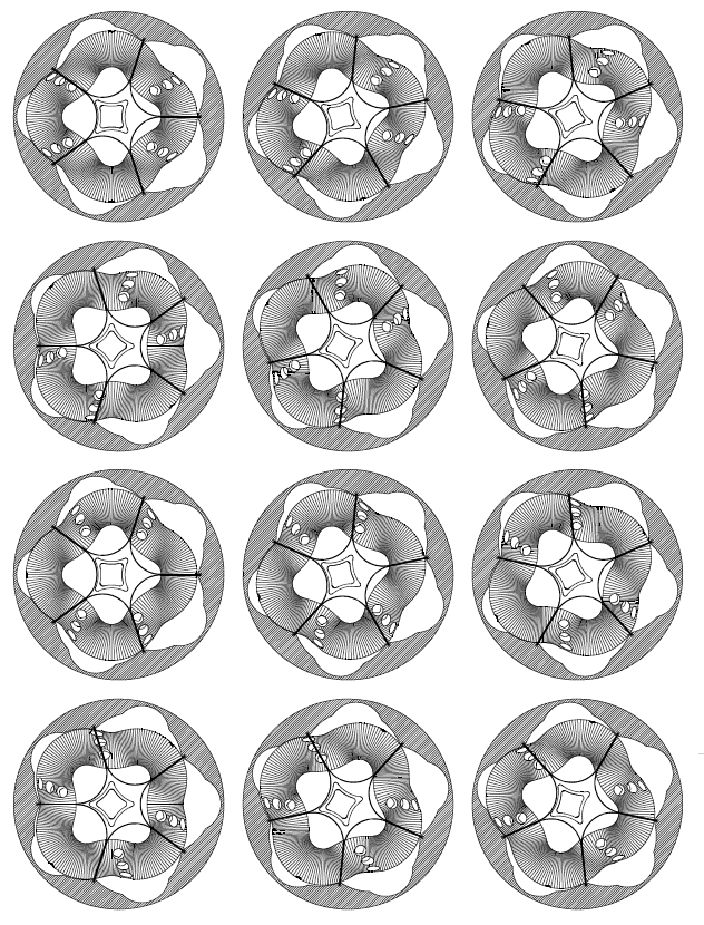
As compared with a Ducati Panigale 1299cc reciprocating piston engine running at the same revs with the revs of the inner body of the PatWankel, the PatWankel provides more than 40% additional time around the TDC (1.15*1.25=1.43)

The 15% longer dwell at the TDC comes from the harmonic (i.e. pure sinusoidal) variation of the combustion chamber volume:
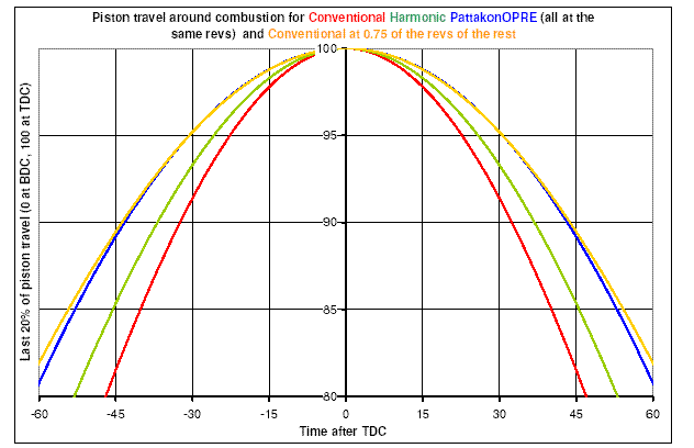
Image

the 1.25 comes from the 225 degrees required in order the chamber to go from its TDC to its BDC (wherein the volume is maximised):
Image

There is plenty of time and a very short distance for the flame to travel, enabling the combustion to complete inside the compact cavity.
Most of the thermal loss happens during the combustion.
The thermal loss continuous during the expansion, however the rate of thermal loss during the combustion is way higher.

Compare it with the thermal loss in the Ducati Panigale 1299 wherein the flame, during the combustion, sweeps the inner surfaces of a wide (116mm diameter) short (about 5mm height) cylinder (like a coin) having abnormal bottom and top (valve pockets etc).
Reasonably, the thermal loss towards the walls during the combustion will be substantially more than in the above PatWankel.

In the conventional Wankel the flame sees way bigger surfaces and has to travel along way longer distances. This explains the extreme thermal loss in the Wankel rotary.

So, there are reasons for lower thermal loss in the PatWankel, despite the bigger area of its wall surfaces, than in a reciprocating piston over-square engine.


Quote from:
http://gasturbinespower.asmedigitalcoll ... id=2467298

“Abstract
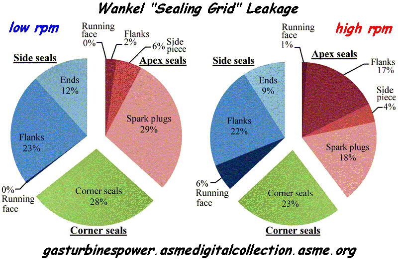
The Wankel rotary engine offers a greater power density than piston engines, but higher fuel consumption and hydrocarbon emissions, in large part due to poor gas sealing. This paper presents a model for the deformable dynamics of the side seal, which completes a set of modeling tools for the comprehensive assessment of the gas leakage mechanisms in the rotary engine. It is shown that the main leakage mechanisms for the side seals are: (1) opening of the inner flank due to the contact with the trailing corner seal, (2) flow through the gap with the leading corner seal, (3) simultaneous opening of both inner and outer flanks due to body force at high speed, and (4) running face leakage due to nonconformability at high speed. The leakage mechanisms are qualitatively validated at low speed with observed oil patterns on the rotor from laser-induced fluorescence (LIF) experiments. Finally, the predicted total leakage area for all the gas seals ranges from 1.5 mm2/chamber at low speeds to 2 mm2/chamber at high speeds, which is in agreement with the previous experimental studies, and the three gas seal types (side seals, apex seals, and corner seals) each accounts for about 1/3 of the total leakage, with minor variation as a function of speed.”
Image

According the above abstract / plot, the leakage is the big problem of the rotary engines.

Take a 650cc single cylinder reciprocating piston engine and make a hole of 1.5mm diameter (1.77mm2 area) on the piston crown towards the crankcase.
No doubt, the engine can still work, however a significant amount of high pressure gas will escape reducing the efficiency (energy is consumed to compress the gas that leaks) and worsening the emissions.

This is the way the Wankel works till now.
The gaps around each combustion chamber have an equivalent total leakage area of 1.5mm2 at low revs, to 2mm2 at high revs.

Compare the leakage from the “running surfaces” with the rest leakage.


The mechanical friction in a rotary engine like the PatWankel 5-cylinder is substantially lower than in an “equivalent” reciprocating piston engine.
There is no valve train.
There are no piston skirts to thrust on cylinder walls.
The four roller bearings on the frame and the sliding of the seals on the working surface are the only cause of mechanical friction.
All the energy / torque passes directly through the shaft of the inner body to the load.
The outer body receives no torque, at all.


If you count all these, things get more than interesting.


You also write:
“the variable gears Ring/Planet gear with the complex cut, is their further information on this?”

The synchronising gearwheels are conventional and cheap.
There is nothing special with them.
And they run unloaded; only when the revs change fast (braking with the engine, for instance) only then the teeth are loaded with inertia load (to accelerate the outer body).


You also write:
“And Manolis the spread sheet you sent me was fine, only comment I have is that later calculations were using previous calculations, ie acceleration used two speed calculations and this can cause the floating point rounding errors to accumulate and why 0.1 + 0.2 != 0.3 under the standard, I also remember that excell has a financial maths package which had some issues with scientific calculations, this was a long time ago thou and their was a difference at that point. Not quite "Intel inside can't Divide" The CSIRO found within a month of the Pentium being released.”

I think it is simpler than this.

The spreadsheet was made for someone who couldn’t calculate the affect of the wrist pin offset on the acceleration of the piston.

For simplicity I took 1 degree steps.

The spreadsheet calculates the position of the piston per crank degree.
Then the spreadsheet takes the change of the piston position for every two successive degrees and calculates the piston velocity per crank degree.
Then the spreadsheet takes the difference of the piston velocity for every two successive degrees and calculates the piston acceleration.

If you want more accuracy, just put more steps ( for instance, from 1 crank degree step, go to 0.1 degree or to 0.01 degree step). But, do you really need such accuracy?


Thanks
Manolis Pattakos
J.A.W.
J.A.W.
109
Joined: 01 Sep 2014, 05:10
Location: Altair IV.

Re: 2 stroke thread (with occasional F1 relevance!)

Post

Hi Manolis, that rotary piston design looks interesting.

Wankel engines ran very hot indeed,
& required auxiliary lubrication directly injected to the rotary piston working face, akin to 2T lube..
( in fact, Mazda Rx7s used the same Mikuni oil pumps as 2T motorcycles)..

Will your machine run sufficiently cooler so as not to require this - which was also an emission control problem..

( & have you checked the added 'Ryger' material from a couple of pages back - for potential patent infringements?)
"Well, we knocked the bastard off!"

Ed Hilary on being 1st to top Mt Everest,
(& 1st to do a surface traverse across Antarctica,
in good Kiwi style - riding a Massey Ferguson farm
tractor - with a few extemporised mod's to hack the task).

manolis
manolis
107
Joined: 18 Mar 2014, 10:00

Re: 2 stroke thread (with occasional F1 relevance!)

Post

Hello J.A.W.

You write:
“have you checked the added 'Ryger' material from a couple of pages back - for potential patent infringements?”

Is there any patent granted to Ryger? (in the patent things get clear, because in the claims the inventor defines what is his/her intellectual property).

Have you understand what differs the engine of Ryger than the conventional 2-strokes? I did not yet. Is it still “top secret” or it is open to the public?


You also write:
“Wankel engines ran very hot indeed,
. . .
Will your machine run sufficiently cooler so as not to require this - which was also an emission control problem..”


The PatWankel engine is expected to run sufficiently cooler.

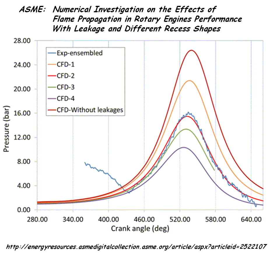
Quote from http://energyresources.asmedigitalcolle ... id=2522107

“Numerical Investigation on the Effects of Flame Propagation in Rotary Engine Performance With Leakage and Different Recess Shapes Using Three-Dimensional Computational Fluid Dynamics”

ABSTRACT

This study was carried out with an objective to develop a 3D simulation methodology for rotary engine combustion study and to investigate the effect of recess shapes on flame travel within the rotating combustion chamber and its effects on engine performance. The relative location of spark plugs with respect to the combustion chamber has significant effect on flame travel, affecting the overall engine performance. The computations were carried out with three different recess shapes using iso-octane (C8H18) fuel, and flame front propagation was studied at different widths from spark location.
Initially, a detailed leakage study was carried out and the flow fields were compared with available experimental results. The results for first recess with compression ratio 9.1 showed that the flow and vortex formations were similar to that of actual model. The capability of the 3D model to predict the combustion reaction rate precisely as that of practical engine is presented with comparison to experimental results. This study showed that the flame propagation is dominant toward the leading apex of the rotor chamber, and the air/fuel mixture region in the engine midplane, between the
two spark plugs, has very low flame propagation compared to the region in the vicinity of spark. The air/fuel mixture in midplane toward the leading apex burns partially and most of the mixture toward the trailing apex is left unburnt. Recommendations have been made for optimal positioning of the spark plugs along the lateral axis of the engine. In the comparison study with different recess shapes, lesser cavity length corresponding to a higher compression ratio (CR) of 9.6 showed faster flame propagation toward leading side. Also, mass trapped in working chamber reduced and developed higher burn rate and peak pressure resulting in better fuel conversion efficiency.
Third recess with lesser CR showed reduced burn rates and lower peak pressure.

Image

End of Quote.


If you combine the above quote / plot with the quote / plot in my previous message (leakage in the Wankel “Sealing Grid”), the Wankel rotary engine has many reasons to run hot.
Instead of making mechanical power by expanding the high pressure gas, a good part of the high pressure / high temperature gas leaks offering no mechanical energy; it just warms the engine. The engine runs, partly, as a burner.

If we could reduce substantially the leakage in the conventional Wankel, an extreme increase of the power output and an extreme decrease of the BSFC are expected.

If the two Quotes are near to reality, a PatWankel (like that at http://www.pattakon.com/PatWankel/PatWankel_W_1.gif ) in a Mazda RX-8 would have a lot more power and a way lower BSFC (gr/kW).
And because the chemical energy of the fuel would turn, in a significant percentage, in mechanical energy, the engine would run colder.


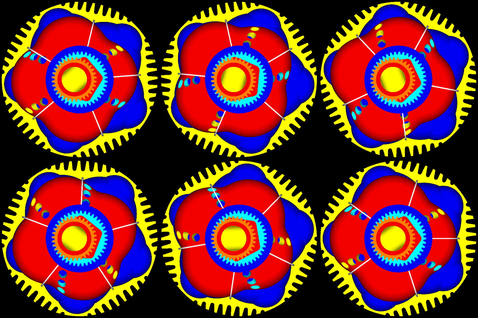
The next reasonable step would be the replacement of the like-Wankel PatWankel with a PatWankel wherein the seals are sliding onto the surface of the inner body, as in the following 5-chamber PatWankel:

Image

and as in the following seven-chamber PatWankel

Image

Image

Image

With the combustion completed inside the compact hemispherical cavity, the expected thermal loss drops significantly.

Combined with the better sealing (gas leakage as in the reciprocating piston engines), things can improve a lot.

Thanks
Manolis Pattakos
J.A.W.
J.A.W.
109
Joined: 01 Sep 2014, 05:10
Location: Altair IV.

Re: 2 stroke thread (with occasional F1 relevance!)

Post

Hi Manolis, your rotary piston design appears to be organically morphing into a turbine...
How would it be, efficiency-wise, in the task of a turbocharger- for F1 use?

Anyhow, have you not seen this: http://www.customfighters.com/forums/sh ... ?p=2354521
Scroll down to the animation, it looks somewhat familiar, no?

Luc Foekema who made grandiose promises on this thread about the 'Ryger' - so far, sans follow-up..
..has posted dyno charts on his facebook site.. also claiming ~65hp from 125cc with a wide torque band..
"Well, we knocked the bastard off!"

Ed Hilary on being 1st to top Mt Everest,
(& 1st to do a surface traverse across Antarctica,
in good Kiwi style - riding a Massey Ferguson farm
tractor - with a few extemporised mod's to hack the task).

manolis
manolis
107
Joined: 18 Mar 2014, 10:00

Re: 2 stroke thread (with occasional F1 relevance!)

Post

Hello J.A.W.

You write:
“Luc Foekema who made grandiose promises on this thread about the 'Ryger' - so far, sans follow-up..
..has posted dyno charts on his facebook site.. also claiming ~65hp from 125cc with a wide torque band..”

Here is Ryger’s engine from outside:

Image

Is there a patent showing the differences / the inventing step Ryger claims for his engine?


Quote from rygerengine.com :

“The Ryger Revo Clean 1 runs on normal petrol instead of a mixture of petrol with 2-stroke oil. Of course this already causes the first big advantage of having a much cleaner emission compared to the traditional 2-stroke engines.
Due to an ingenious design of the cylinder in combination with the piston and a bottom plate there is no fuel mixture in the crankcase but the fuel will only come underneath the piston where it is compressed and then being released on top of the piston after which ignition takes place.
With the Ryger Revo Clean 1 all the bearings run through the lubricant which is present in the crankcase and the piston is being lubricated via condensed lubrication. Also the gudgeon pin is being lubricated via condensed lubrication. This has resulted in a high degree of durability of the Ryger Revo Clean 1.
All the advantages of the Ryger Revo Clean 1 will help to get the best performance on a kart circuit. Due to the extreme output , the Ryger Revo Clean 1 is the strongest engine available in the 125CC category.

BUY NOW”

End of Quote


The GB 2,533,619 patent granted for the PatTwo project (at http://www.pattakon.com/pattakonPatTwo.htm ) discloses 2-strokes characterized, among others, by what Ryger claims as the big advantage of his engine, i.e.:

“there is no fuel mixture in the crankcase but the fuel will only come underneath the piston where it is compressed and then being released on top of the piston after which ignition takes place”

Image

Image

Similarly for the patented Tilting Valve, PatMar and PatPortless projects (at http://www.pattakon.com/pattakonTilting.htm , http://www.pattakon.com/pattakonPatMar.htm and http://www.pattakon.com/pattakonPatPortLess.htm respectively).


You also write:
“Anyhow, have you not seen this: http://www.customfighters.com/forums/sh ... ?p=2354521
Scroll down to the animation, it looks somewhat familiar, no?”

The guy who posted the animation (it is one of the versions of the tilting valve) was, apparently, confused. The patent he mentions has nothing to do with the animation.


You also write:
“your rotary piston design appears to be organically morphing into a turbine...
How would it be, efficiency-wise, in the task of a turbocharger- for F1 use?”

Reasonably, it would be good. The dead volume is quite small, the friction is reduced, the pressure difference can be very high in a single stage.

However it would be a pity to use it as the supercharger of a F1 reciprocating piston engine, when it can totally replace the reciprocating piston engine.

Here they are shown, among others, the passageways for the air / mixture / exhaust gas through the inner body:

Image

Image

The free flow, the compact / lightweight design and the reduced friction make it good for several applications (from aero engine, to sport bike engine, to racing engine etc).

Thanks
Manolis Pattakos

Tommy Cookers
Tommy Cookers
621
Joined: 17 Feb 2012, 16:55

Re: 2 stroke thread (with occasional F1 relevance!)

Post

iirc the Wankel was of course used as a supercharger in the 1956? NSU that took the motorcycle speed record

uniflow
uniflow
36
Joined: 26 Jul 2014, 10:41

Re: 2 stroke thread (with occasional F1 relevance!)

Post

Here Manolis, the sleeve engine finished in real metal and running for real, not on a computer.
https://youtu.be/6keqpL3rmwk
https://youtu.be/TmXFkbD3s5g
Ethanol fueled, fuel injected twostroke, running in the real world
https://youtu.be/CnIemdISKrM

manolis
manolis
107
Joined: 18 Mar 2014, 10:00

Re: 2 stroke thread (with occasional F1 relevance!)

Post

Hello Uniflow.

You write:
“Here Manolis, the sleeve engine finished in real metal and running for real, not on a computer.
https://youtu.be/6keqpL3rmwk
https://youtu.be/TmXFkbD3s5g
Ethanol fueled, fuel injected twostroke, running in the real world
https://youtu.be/CnIemdISKrM


Thanks for the videos. Congratulations for the project.


You know, first hand, that it takes time from running on a computer to running for real.

Unless I am wrong, your “sleeve valve” design took several years to get ready for tests.

Long ago we had a discussion in this forum about sleeve valves like those in RR-Crecy, those at http://www.pattakon.com/Sleeve.htm, about the obvious advantages of the Opposed Piston 2-stroke engines over the sleeve valve 2-stroke, say, like the “real” (made of metal and running on Diesel fuel) PaTOP Opposed Piston 2-stroke engine:


which, among others, has a single crankshaft, is fully balanced, provides some 30% additional time to the “directly injected” Diesel fuel to get burned at high expansion ratios etc, etc; more at http://www.pattakon.com )


So give the PatWankel a chance (as a fresh project) and, if you like, comment on its technical disadvantages.


On the other hand, when with only two parts you have the freest four-stroke breathing of several chambers (three, five, seven etc), no vibrations at all, the lowest friction loss etc

Image

things get interesting, theoretically at least

Thanks
Manolis Pattakos

uniflow
uniflow
36
Joined: 26 Jul 2014, 10:41

Re: 2 stroke thread (with occasional F1 relevance!)

Post

I guess what I'm saying Manolis is pick on one or two real good ideas and finish them off, in the real world. In a motorcycle or personal flyer, show the unbelievers. I've spent time at US air and trade shows and I get pissed off that all with all the pretty pictures and hype, nothing real and on many occasions I can see that what is proposed will fail due to real world conditions (like heat).
You are right my sleeve engine has taken years but I have to work for a living in between and I don't take my own advice with TOO MANY projects on the go at once. At least at the end of the day I get to ride / fly them and have some fun. As for the sleeve engine now I have a motorbike I can ride that no one else has and do real world testing. Money isn't everything Manolis.

manolis
manolis
107
Joined: 18 Mar 2014, 10:00

Re: 2 stroke thread (with occasional F1 relevance!)

Post

Hello Uniflow.

You write:
“I guess what I'm saying Manolis is pick on one or two real good ideas and finish them off, in the real world. In a motorcycle or personal flyer, show the unbelievers. I've spent time at US air and trade shows and I get pissed off that all with all the pretty pictures and hype, nothing real and on many occasions I can see that what is proposed will fail due to real world conditions (like heat).
You are right my sleeve engine has taken years but I have to work for a living in between and I don't take my own advice with TOO MANY projects on the go at once. At least at the end of the day I get to ride / fly them and have some fun. As for the sleeve engine now I have a motorbike I can ride that no one else has and do real world testing. Money isn't everything Manolis.”


Thanks for the advice.

Take a look at http://www.pattakon.com/pattakonRod.htm and http://www.pattakon.com/pattakonRoller.htm .

Here is the video of the car on the road:


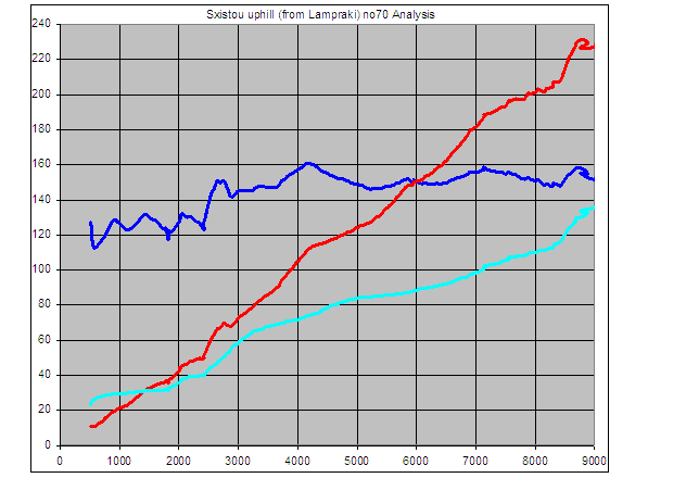
Here is a data-log plot:

Image

showing, among others, the potential of the VVA-roller at higher than 9,000rpm revs.

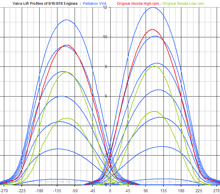
Here is the comparison of the infinite valve lift profiles provided by the VVA-roller as compared to the only two (and mild in comparison) valve lift profiles of the “famous” Honda VTEC of the original car:

Image

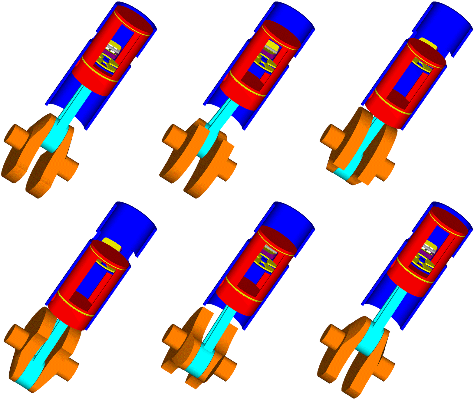
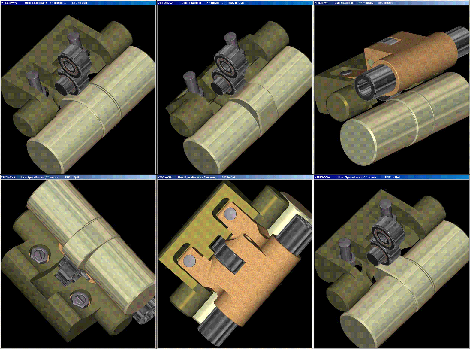
Here is how the mechanism of the VVA-roller works and is controlled:

Image

Without a throttle-valve, the intake valves control the load from idling to the red line.

Then read the http://www.pattakon.com/DVA_files/pattakonVVAs.pps , the chapter regarding the modifications in the ECU / injection / ignition / sensors.


When BMW was straggling to rise the red line for just 300rpm (from 5,600 to 5,900rpm) in their valvetronic VVA engines (at Engine Expo Stuttgart Germany, the engineer in charge of the “cooperation” between BMW and Peugeot / Citroen told us that the valvetronic engines provided by BMW to Peugeot were guaranteed only if the rev limit was not at all violated),
we had a couple of prototype cylinder heads in cars on the roads making tests and enjoying their running.

The Honda VVA-roller was happy to rev at 50% higher revs than BMW’s valvetronic engines (the one hand-made, the other having some parts made with 0.008mm accuracy as BMW claimed).
The rev limiter was set at “only” 9,000rpm because the rest engine would not stand more revs.

By the way: the valvetronic of BMW is exclusively for intake valves, the pattakon VVAs control both, the intake and the exhaust valves.


We enjoined the driving of the prototype cars, their acceleration, their low idling, their sound, their reliability etc.


However, having some cars or motorcycles on the road for tests is not panacea.
The car makers can ignore you as easily as before having the prototype.
You know this from first hand, I suppose.


Fortunately we did not focus on the production of the rod-VVA, roller-VVA, rod-roller VVA , but proceeded a little further with the DVVA (the desmodromic VVA at http://www.pattakon.com/pattakonDesmo.htm ) which combines its “parent” VVA advantages offering additional characteristics and even higher rev limits for the poppet valve engines.

We did not put the DVVA in a car or bike because we know it works and is reliable (its “parent” projects proved more reliable than the original cars).


Fortunately we did not limit ourselves in the DVVA, and the PatRoVa rotary valve was borned (no rev limit, no reciprocating parts, unique way of taking the combustion loads internally leaving the bearings unloaded, no friction in the valve train etc, etc).

And who knows what is to come.


In EcoMotors they have spend, so far, some 100 million dollars (the 23,5millions from Bill Gates of Microsoft) for the OPOC, an engine still having several issues to address.
And they have not, yet, prototype cars / trucks on the roads for real tests despite the thousands of articles written for the OPOC in the Internet and despite the big names between their investors.

Take the PatOP (which, among others, has some unique characteristics like the pulling rod architecture and the additional dwell of the piston around the combustion dead center) and compare it to the OPOC of EcoMotors.

We thought to put The PatOP prototype engine on a buggy / ATV for demonstration. We did not manage to do it, yet.


Fortunately we didn’t focus only on the OPRE / PatOP opposed piston engines and several other promising projects were born (PatMar, Asymmetric Timing 2-strokes, PatTwo, the PatHead VCR etc, etc).


Fortunately we didn’t focus on the reciprocating piston engines and the PatWankel project was born.


Fortunately we didn’t focus on engines, and projects like the PatBox CVT, the PatDAN constant velocity joint etc, etc were born.


Around each one of these projects a company like the EcoMotors or like the Achates Power could be built.

In the hindsight, what I see is that our choice "to stay not focused" was correct and productive, at least so far.

Thanks
Manolis Pattakos

Brett54
Brett54
0
Joined: 05 Nov 2011, 08:48

Re: 2 stroke thread (with occasional F1 relevance!)

Post

Any pictures of a v4 2stroke crank? eg. NSR500
Are they a splayed inline 4 to achieve separate big ends and crankcase compression?

Tommy Cookers
Tommy Cookers
621
Joined: 17 Feb 2012, 16:55

Re: 2 stroke thread (with occasional F1 relevance!)

Post

re the picture, I'll second that
some time ago my suggestion iirc was that the 'big bang' NSR of mythical efficacy had a N-S-N-S crankshaft (or did I say N-N-S-S ?)

btw
given that telescopic forks must be eg in Moto GP have reached the lean angle beyond which they cannot work well due to friction .....
as the 2 stroke motorcycle is much lighter (than the 4 stroke) it needs less lean (for a required lean of combined rider + machine mass)

the Motoinno like most other HCS does not seem to allow 'road-normal' steering geometry ?

btw 2
a rotary engine with more than the usual Wankel 3 rotor faces - has via the 'crankshaft' gearing a higher torque/lower rpm output ? (than the usual)
this is very valuable for aviation, allowing greater thrust efficiency by using a bigger prop, without needing a reduction gear
Last edited by Tommy Cookers on 04 Jan 2017, 13:57, edited 1 time in total.