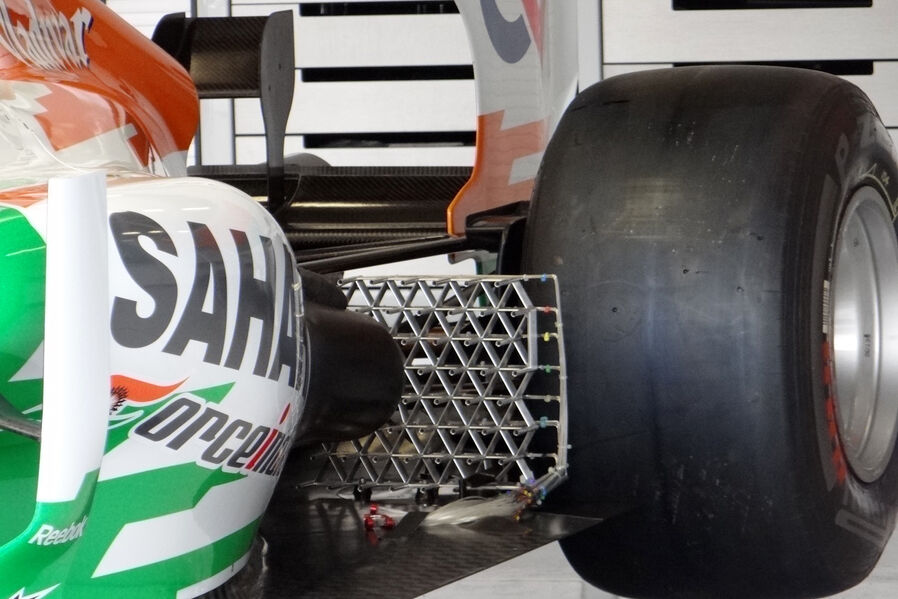
Kiel probe sensor arrays

Here are our CFD links and discussions about aerodynamics, suspension, driver safety and tyres. Please stick to F1 on this forum.
User avatar
Forza
238
Joined: 08 Sep 2010, 20:55

Kiel probe sensor arrays

Post

Kiel probe sensor array

Image
Last edited by mx_tifoso on 11 Jul 2012, 12:03, edited 1 time in total.
Reason: split from VJM05 thread

marcush.
marcush.
159
Joined: 09 Mar 2004, 16:55

Re: Force India VJM05

Post

those aero rakes are modifying the flowfield so much i doubt you could get any useful information from them ..I wonder what the guys are trying to find out...the rake is bigger and has more influence as the tabs and winglet they position at strategic points....so what? :roll:
Maybe someone can explain ...but for me having a complete harness placed randomly on top of an aerosurface is already so counterintuitive ...why would you try to get clean airflow in the area when you are trying to get accurate minute measurements placing all that stuff in the area... you are just measuring the modified flow at best ...so what can be derived from that??

User avatar
PlatinumZealot
559
Joined: 12 Jun 2008, 03:45

Re: Force India VJM05

Post

It works. All you have to do is model the rakes in the windtunnel and CFD.
🖐️✌️☝️👀👌✍️🐎🏆🙏

Racing Green in 2028

Owen.C93
Owen.C93
177
Joined: 24 Jul 2010, 17:52

Re: Force India VJM05

Post

n smikle wrote:It works. All you have to do is model the rakes in the windtunnel and CFD.
Works for correlation checks but not much so much for discovering exhaust plume and mapping which they seem to be doing. I'd have thought they'd have tried to put as much equipment downwind as possible.
Motorsport Graduate in search of team experience ;)

marcush.
marcush.
159
Joined: 09 Mar 2004, 16:55

Re: Force India VJM05

Post

proving your modified flowfield does correlate is in NO WAYS a prove that things will correlate without .This is really the problem with CFD as well ..you just don´t know WHY or why not your sim does correlate or not so it may well be you got near perfect prediction in some cases but change your part and arrive at a phenomenon in reality that is not included in your sim and voila your predictions will diverge from reality big time.
To me it´s not the question if it may be useful to investigate those flow fields but the way teams approach this .My claim is:
if you are looking at minute changes -in below 5% range -it does absolutely make no sense to introduce a say 5 % change of area ..
It´s like taking a vibration measurement on a small or flexy part using a 10gramme accelerometer stuck to the item.No correlation whatsover will help you derive ANY useful or relevant data.You need just a different METHOD (optical measurement, interferometer laser measuring ).
I´m pretty sure direct measurements will just not do when it comes to optimising flows ..

Why not feed a stream of particles down the car at speed and capture with a high speed camera,maybe sending marking a particle every half second and analysing the path of this particle along the car ...you could not only see wher it goes but also how quick it goes...voila, perfect data generated .

User avatar
rscsr
51
Joined: 19 Feb 2012, 13:02
Location: Austria

Re: Force India VJM05

Post

marcush. wrote: ....
Why not feed a stream of particles down the car at speed and capture with a high speed camera,maybe sending marking a particle every half second and analysing the path of this particle along the car ...you could not only see wher it goes but also how quick it goes...voila, perfect data generated .
Well, A wind tunnel of Toyota is using such a system. But the Problem with such a system is, that you can't use it to long, because it would change the density and other properties of the air in the tunnel.
Toyota used some fluid, which has been sprayed into the strean, and a laser lightened only a certain plane to photograph the particles. Then they shot another picture (shortly after) and looked, how the particles have moved. (Or maybe the used two planes, which are just a mm or so apart?!)
I think, that it was in a Racecar Engineering, but I really don't know exactly where I read it.
marcush.
marcush.
159
Joined: 09 Mar 2004, 16:55

Re: Force India VJM05

Post

know that -


http://www.tecplot.com/Community/CaseSt ... veeng.aspx

This little piece also shows that sh..t in means sh..t out when it comes to cfd ...if your conditions and modeling is not representing the real world ,you may get completely wrong development directions ...and fall of the cliff at some time.


The obstructive grid as used by some teams is complete nonsense to me to get accurate representations of the accuracy needed.No matter how much you could possibly correlate it is of no importance .

mods please shift this discussion to the appropriate thread ...I think we have two or three of them already..sorry for infecting this one..

User avatar
hollus
Moderator
Joined: 29 Mar 2009, 01:21
Location: Copenhagen, Denmark

Kiel probe sensor arrays

Post

Marcush, I don't think those Kiel probe sensor arrays are being used to optimize anything. They are crude and have a huge cross section, for sure they will affect the flow.
They seem to pop up about once or twice per team, and then be gone, and they pop up mostly behind the exhaust. I think they are being used as flo-viz in an area where there are no surfaces. Flo-viz is not used to optimize, it answers the question do we have separation here or not? They know the sensor arrays are changing the flow somewhat, but it is mostly about finding where the flow (exhaust flow, easy to detect by temperature) roughly goes (for example, how much does it spread vertically at 120Km/h and 15000RPM?). For that they yield a nice (rough) 4-D map (vertical, horizontal, speed, RPM).
They use it once, see if the models are at least in the right ballpark, then they can continue to develop the models. As you said, a rough measurement to make sure that there is no phenomenon not included in their models suddenly popping up. If your exhaust plume were to go straight to the outside tire when you are above 16000RPM and below 100Km/h, because the exhaust trips the downwash slot (just a random example), neither wind tunnel nor CFD nor pressure sensors would tell you, but you would still be frying that one tire for 5 seconds a lap in Loews.
Rivals, not enemies.

marcush.
marcush.
159
Joined: 09 Mar 2004, 16:55

Re: Force India VJM05

Post

But you have IR -probes to see instantly temperature changes the texys sensors are incrdibly accurate and can measure up to 8 separate areas in one row without disturbing the flow ....
I understand your reasoning and by the looks of things this is what they seem to investigate ..but still it seems intuitively wrong to put something that restrictive into your flowfiled to check what´s going on...it would be very naive to think your grid does only change flow and pressure downstream ....

marcush.
marcush.
159
Joined: 09 Mar 2004, 16:55

Re: Force India VJM05

Post

another example ...

Image

Owen.C93
Owen.C93
177
Joined: 24 Jul 2010, 17:52

Re: Force India VJM05

Post

Well that's fine because it's not changing the flow prior to the tubes by a significant amount. FI had a huge box right infront of it for all the cabling and logging. It would make more sense to put it behind the sensors.
Motorsport Graduate in search of team experience ;)

User avatar
Gridlock
30
Joined: 27 Jan 2012, 04:14

Re: Force India VJM05

Post

marcush. wrote:it would be very naive to think your grid does only change flow and pressure downstream ....
It would be naive to think that the effects of the grid aren't very, very well-known and modelled - IE of course it changes things, but of course they know exactly how to strip this out of the data. There's no restrictions on running these grids through wind-tunnels.
#58