2014 front wing endplate design

Here are our CFD links and discussions about aerodynamics, suspension, driver safety and tyres. Please stick to F1 on this forum.
Post Reply
User avatar
raymondu999
54
Joined: 04 Feb 2010, 07:31

2014 front wing endplate design

Post

With the 2014 front wing regulations, what do you all think will be the standard concept everyone converges for endplate design? I don't mean specifically, but rather main concepts, such as the 2009 wings forced teams to go to an outwash endplate design.

Surely an outwash wing would still just direct air to the middle of the front tyres would it not? And it would be too wide for the endplates to start directing air inwards, like the old 2007/2008 style wings? Does anyone know how the dimensions of the 2014 front wing compare, or will compare, to the 2008 regulation wings?
失败者找理由,成功者找方法

Richard
Moderator
Joined: 15 Apr 2009, 14:41
Location: UK

Re: 2014 front wing endplate design

Post

Good points.

It'd be nice to see some CFD images for the various generations of front wing to see what goes where. At the moment we can only surmise that some goes outside, some under and some over.

volarchico
0
Joined: 26 Feb 2010, 07:27

Re: 2014 front wing endplate design

Post

**Cue ringo and his CFD followed by scores of detractors saying that home-grown CFD shows us nothing**

PNSD
3
Joined: 03 Apr 2006, 18:10

Re: 2014 front wing endplate design

Post

richard_leeds wrote:Good points.

It'd be nice to see some CFD images for the various generations of front wing to see what goes where. At the moment we can only surmise that some goes outside, some under and some over.
http://www.f1-forecast.com/pdf/CRANFIEL ... 20WING.pdf

User avatar
ringo
225
Joined: 29 Mar 2009, 10:57

Re: 2014 front wing endplate design

Post

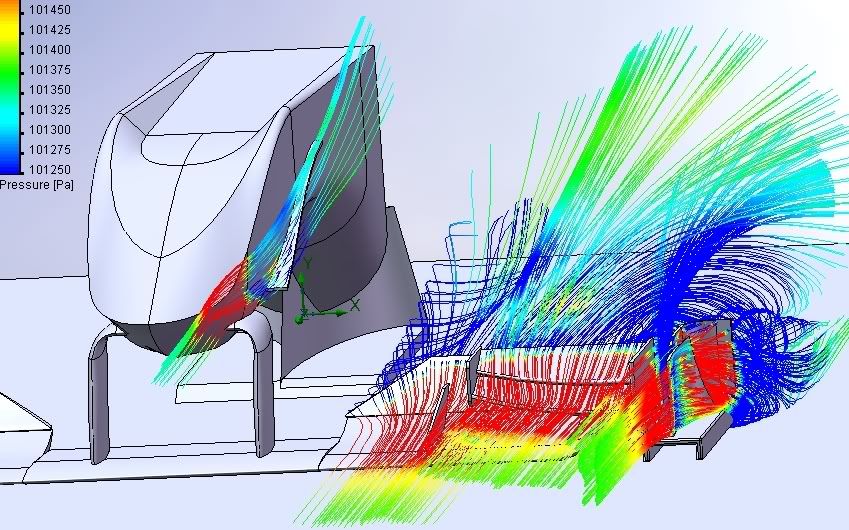
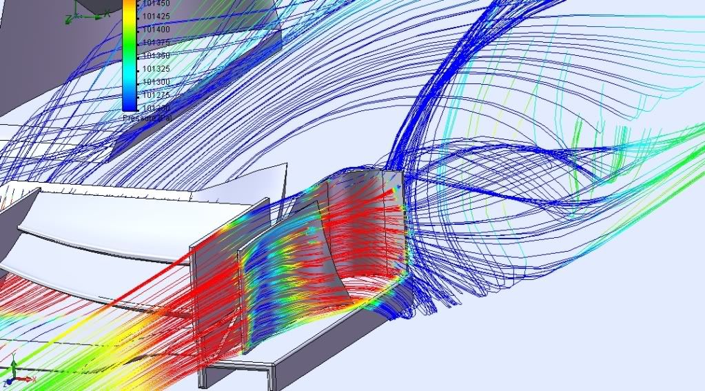
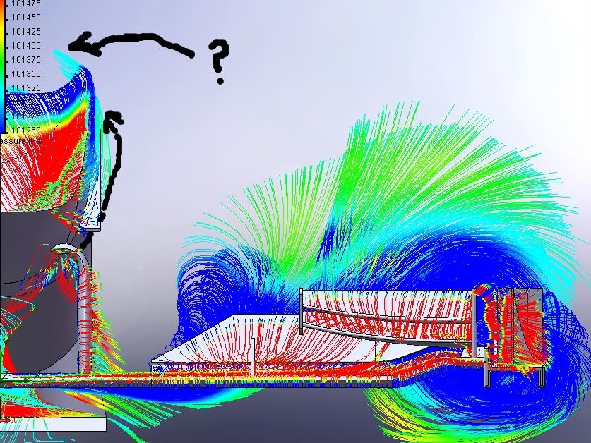
kinda old post from 2010 forum battles about nose cone and wing designs, but it may still be of some use:

Image
Image
Image
if i had the computing power i have now we could be looking at longer streamlines and much better details; though this is pretty acceptable.

The sidewash end plates actually help downforce creation. It pushes air wide to lower pressure along the sides of the car, which makes the whole floor more effective.

Mclaren didn't realize this in 2009, hence they poor performance in the early part of the season.


This wing is utter rubbish in terms of how pretty and organic it looks, but it has all the fundamental shapes necessary.
For Sure!!

User avatar
matt21
86
Joined: 15 Mar 2010, 13:17

Re: 2014 front wing endplate design

Post

FIA wrote:3.7.5 Ahead of the front wheel centre line and between 750mm and 825mm from the car centre line there must be bodywork with a projected area of no less than 95,000mm2 in side view. Any intersection of this bodywork with a lateral vertical plane or a horizontal plane must form one continuous line.
If I read this correct, multi-element wings and endplates are gone.

Richard
Moderator
Joined: 15 Apr 2009, 14:41
Location: UK

Re: 2014 front wing endplate design

Post

I read that as requiring closed sections. You can still have multi elements

User avatar
raymondu999
54
Joined: 04 Feb 2010, 07:31

Re: 2014 front wing endplate design

Post

Given we didn't really settle on a final answer here - is it too much to ask for more people's opinions on the matter? :mrgreen:
失败者找理由,成功者找方法

CBeck113
51
Joined: 17 Feb 2013, 19:43

Re: 2014 front wing endplate design

Post

matt21 wrote:
FIA wrote:3.7.5 Ahead of the front wheel centre line and between 750mm and 825mm from the car centre line there must be bodywork with a projected area of no less than 95,000mm2 in side view. Any intersection of this bodywork with a lateral vertical plane or a horizontal plane must form one continuous line.
If I read this correct, multi-element wings and endplates are gone.
I tend to agree with this, but this only implies to the endplates. Multi-element endplates should be banished by this, since the "one continuous line" means exactly that - only one element in that plane. I do believe that this element can be curved (using the 75mm difference specified in the rule), otherwise the rule would be "one continuous straight line". The form of this plate is also not limited by this specific rule, since there is only a specified minimum surface area. BUT, add this to the lower nose and, more importantly, the lower tub, and it will be much more difficult to get air past the front tires. Unless, of course, there is no minimum track width for the front axle, which could lead teams to a trade-off of mechanical traction for better aerodynamics...or variing track widths for different tracks.
I still need to go through all the 2014 rules to get a better overview of the possibilities, so I am more than ready to be proven wrong...
“Strange women lying in ponds distributing swords is no basis for a system of government. Supreme executive power derives from a mandate from the masses, not from some farcical aquatic ceremony!” Monty Python and the Holy Grail

User avatar
turbof1
Moderator
Joined: 19 Jul 2012, 21:36
Location: MountDoom CFD Matrix

Re: 2014 front wing endplate design

Post

I presume cutouts will still be possible, like what we see at the floor? Holes which are finely connected to the edge of the endplate with a small cut.
#AeroFrodo

TryHard
9
Joined: 13 Jan 2004, 11:46

Re: 2014 front wing endplate design

Post

turbof1 wrote:I presume cutouts will still be possible, like what we see at the floor? Holes which are finely connected to the edge of the endplate with a small cut.
I'm not sure on that, as the rules states "any section"... a section taken in an area of a cut-out, or a return shape (think a U) will result in two sections, which is precluded, even if they are both continuous.

At a guess, much simpler endplates should result (I guess thats the intention!), although not sure how that requirement relates in terms of the endplate/wing section interfaces... :wtf:

Blanchimont
214
Joined: 09 Nov 2012, 23:47

Re: 2014 front wing endplate design

Post

The regulations have changed since the post on article 3.7.5 was made.
The current article doesn't mention the "any intersection [...] must form one continuous line" part, so the discussion about it is not relevant! :wink:
We'll see the same general front wing design ideas as now, the only difference is the total width is reduced to 1650mm.
Dear FIA, if you read this, please pm me for a redesign of the Technical Regulations to avoid finger nose shapes for 2016! :-)

User avatar
turbof1
Moderator
Joined: 19 Jul 2012, 21:36
Location: MountDoom CFD Matrix

Re: 2014 front wing endplate design

Post

I am not sure about that. Pre-2009 they used the endplates to get the air inboard of the wheels.
#AeroFrodo

Blanchimont
214
Joined: 09 Nov 2012, 23:47

Re: 2014 front wing endplate design

Post

turbof1 wrote:I am not sure about that. Pre-2009 they used the endplates to get the air inboard of the wheels.
Well, can't be 100% sure about that, of course.
But in 2008 the maximum front wing width was 1400mm, compared to 1650mm in 2014 and 1800mm in 2013. That's a big difference and with the 1400mm front wing the front wing endplates where almost in the same plane as the inner surface of the wheels. The 2014 endplates will be located between the inner and the outer surface of the wheel.

So, for me it's unlikely that the teams will try to guide the air to the inner side of the wheel next year, but we'll see.
Dear FIA, if you read this, please pm me for a redesign of the Technical Regulations to avoid finger nose shapes for 2016! :-)

McMrocks
32
Joined: 14 Apr 2012, 17:58

Re: 2014 front wing endplate design

Post

turbof1 wrote:I am not sure about that. Pre-2009 they used the endplates to get the air inboard of the wheels.
yes they did:
http://bc02.rp-online.de/polopoly_fs/1. ... 326405.jpg

but if this drawing, posted in the "2014 rules converted to 2012 rules", is correctly the endplate is somewhere near the middle of the tyre:
http://img827.imageshack.us/img827/8017 ... twing2.jpg

I'm no expert but i think if they try to get the air inboard they would lost downforce. Remember the current endplates which push the air to the outside generate something like a diffuser effect(don't know better how to describe) below the wing. But if they are bend inwards wouldn't it increase the pressure below the wing?

Post Reply