The internal construction of the rear crash structure had bothered me for a long time. I knew it held hidden secrets, from construction, to internal layout, to wall thicknesses, to hard point mounting methods, and so on. This, I needed to know all about, for future constructions.
It really is a good item to study, since its design is not to be sneezed at considering its function.
Keep in mind it needs to protect the rear and dissipate a lot of energy should the need arise.
The amount of energy it does dissipate is really amazing, there was a lot to learn from this part.
If you going to share images, mention my name, watermarking them takes time I dont have, it took a good bit of time and a bit of money to do all this, and it also took three new bahco handsaws. Given that Ive spent considerable time picking strands and shards from my hands and arms for the past while its the least you can do.
Im not going to do much talking about its construction,(famous last words) as for someone that has a keen eye, the pictures will be more than enough.
Given that these sort of images do not exist, it was pretty exciting getting inside it.
What you see below can be applied to a lot of things, from simple structures, to racing tubs, construction methods are similar(!but fibre direction is not!).
The age of this structure is 1997, I know a lot has progressed since then, but its a start, and should be good starting info should you want to dip your toes into something composite. Its construction could be a good starting point for a test structure to be based on. Obviously, You dont get the full idea of filament direction, or layup plan, but you do get the basics in the form of images for once, and not mildly descriptive text.
Im sure, by the end of this, I will have a few guys saying that ''I could have told you how it was made without you cutting it up'' Well, thats great, its a shame they wouldn't write it down, draw it,or discuss it without having to twist their arms off.
I understand that some cant say much, but surely, 15yrs odd on, that may not be the case. Or, perhaps there is so many involved in one part, no one guy can describe it all, as he may not be present for all construction. Who knows.
There is a large grey area out there in relation to composite/comb construction, and the mounting methods of various hard points.
I do know loads on hard points differ, but its a start.
Hard point mounting is also a very easy thing for someone to breeze over and appear to know what they are talking about. But, until you actually sit down, with a bunch of different colour markers(representing layers), the order at which you place the hard point, and what you do to keep it in there, without imposing on the main structures strength becomes not so apparent to the designer.
Enough talk...onto the part.
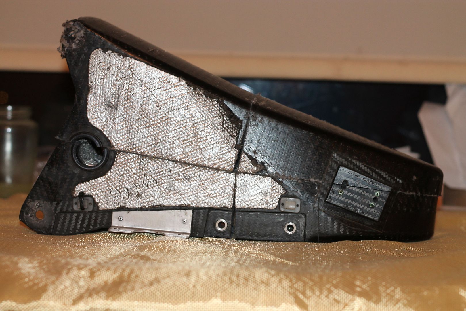
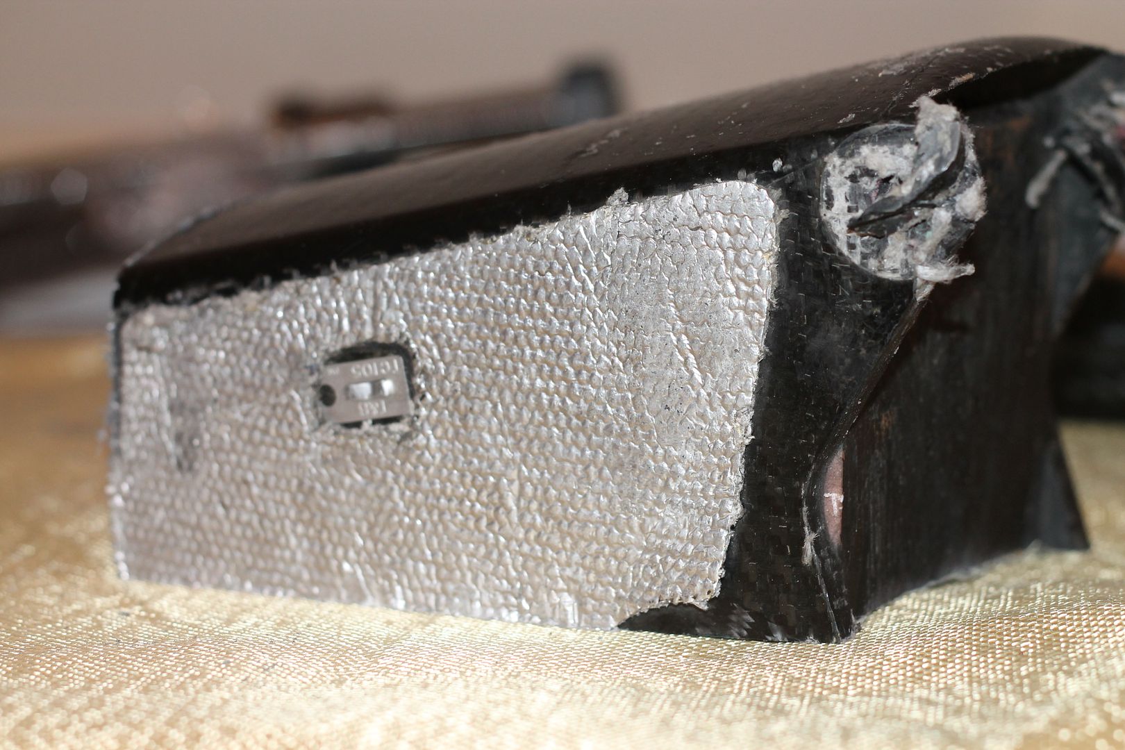
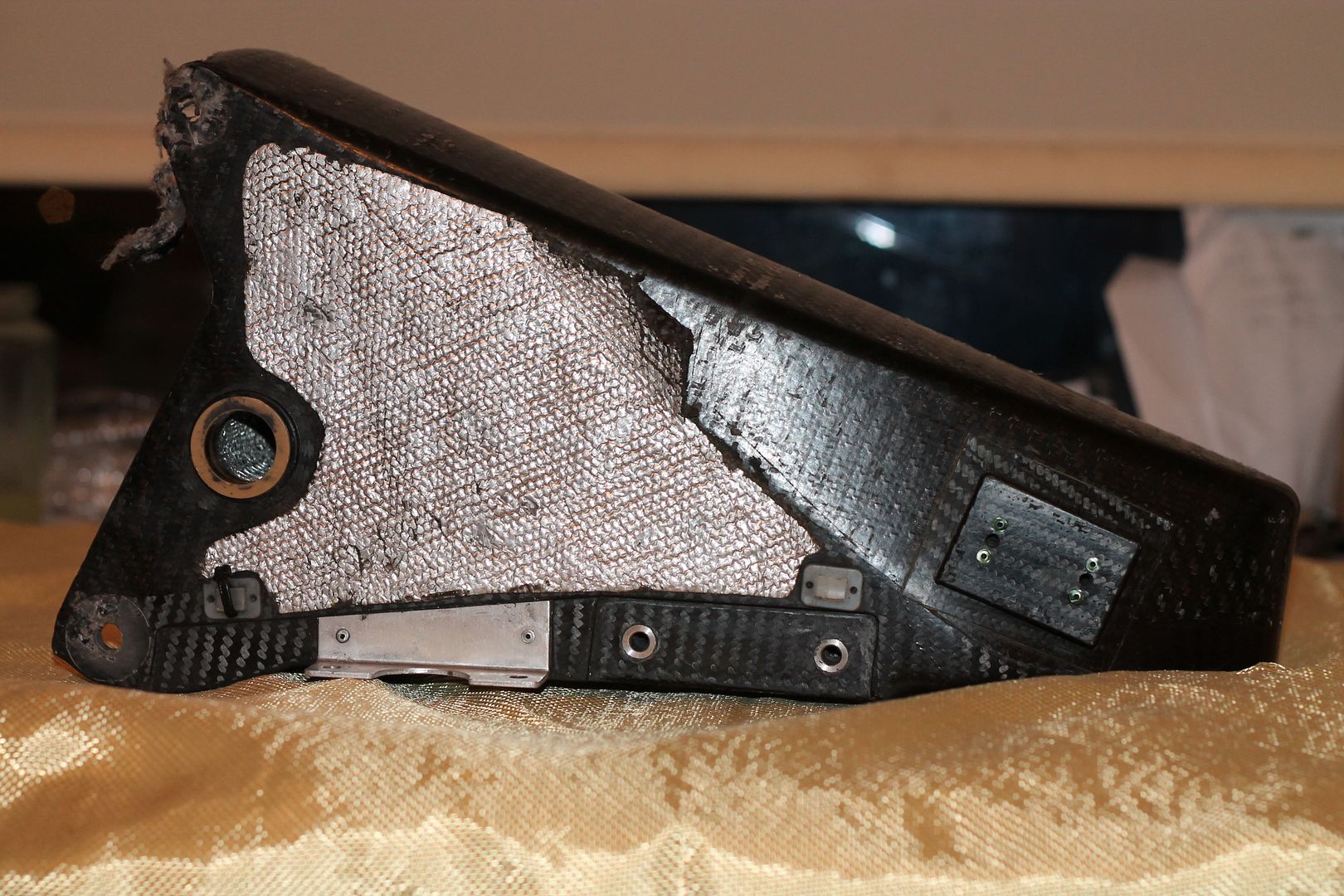
Its external construction is pretty simple, its laid into a two piece mould tool, the part line not straight, but instead following as it does on contoured parts, the point along the side where the two draft angles converge.
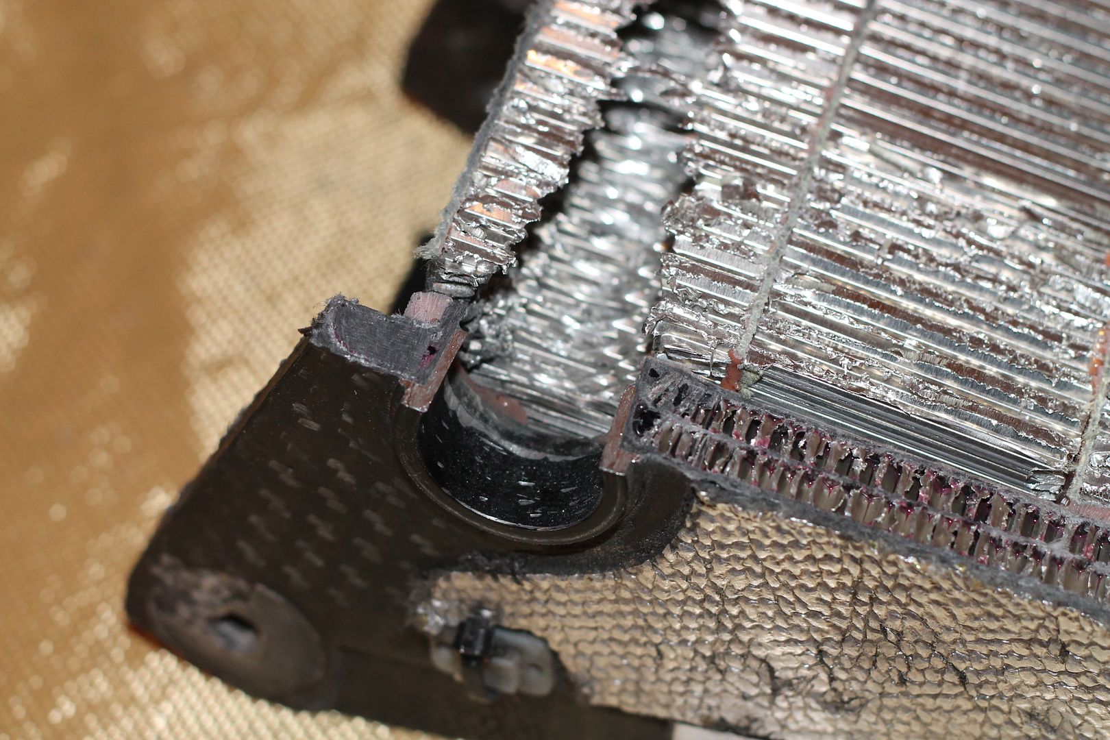
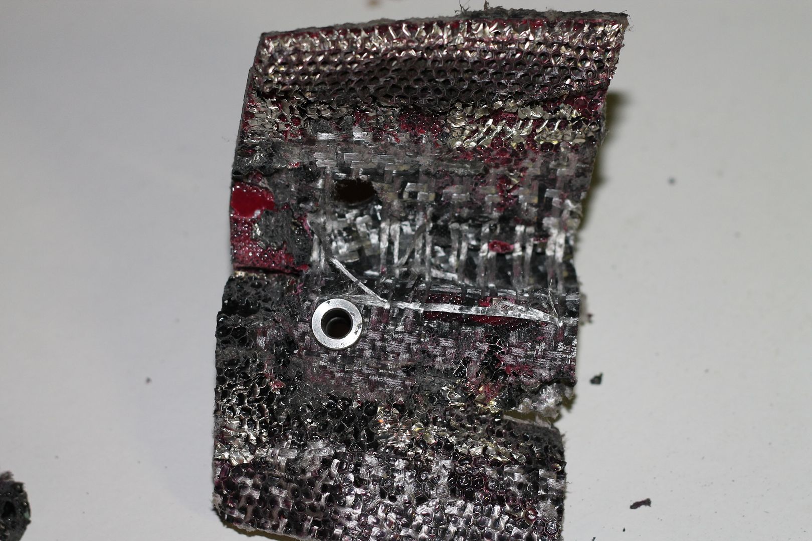
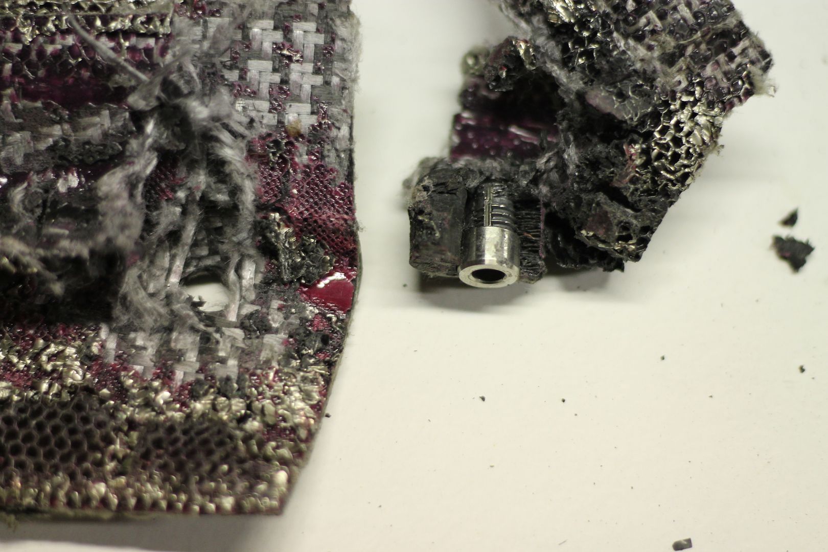
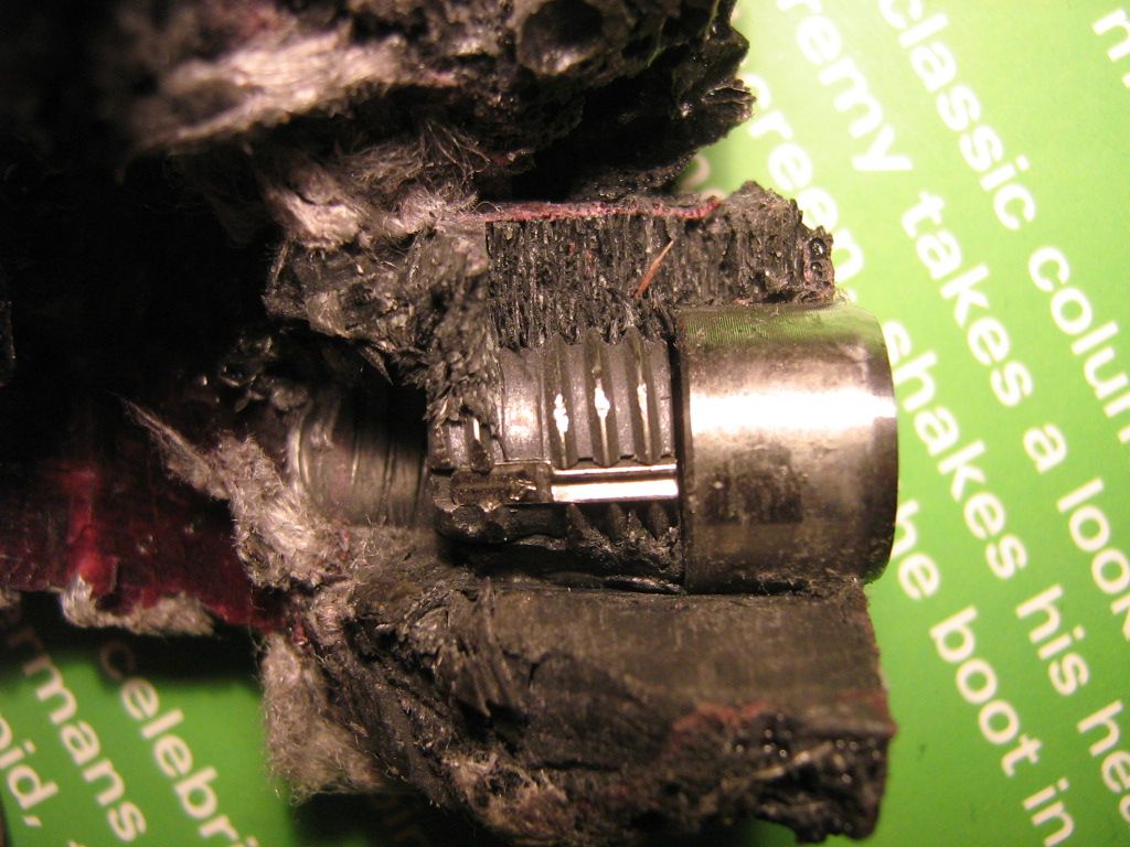
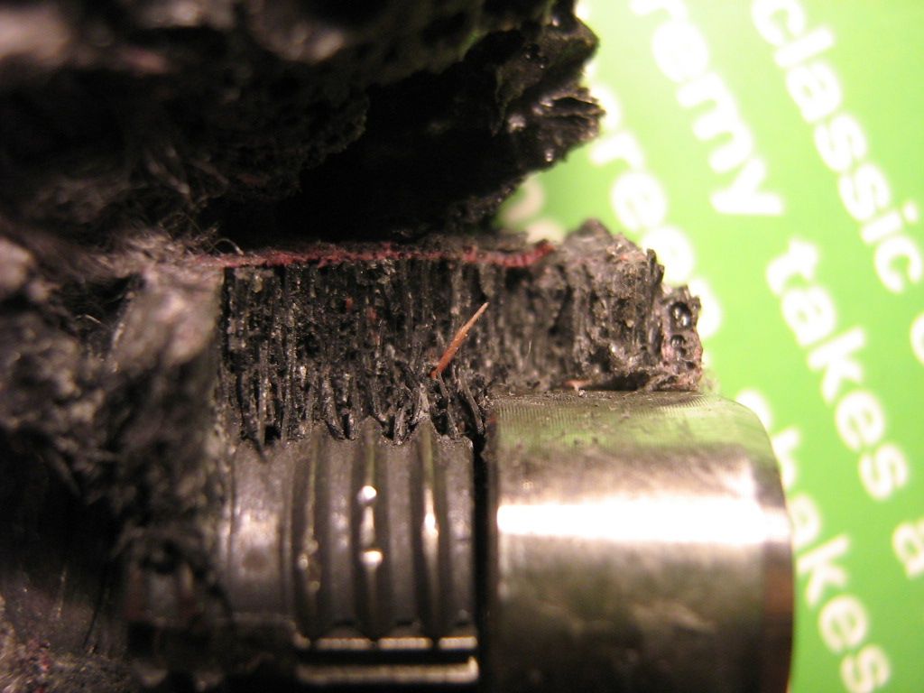
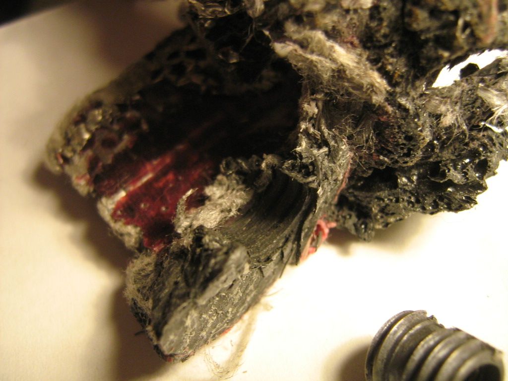
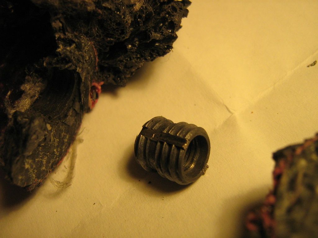
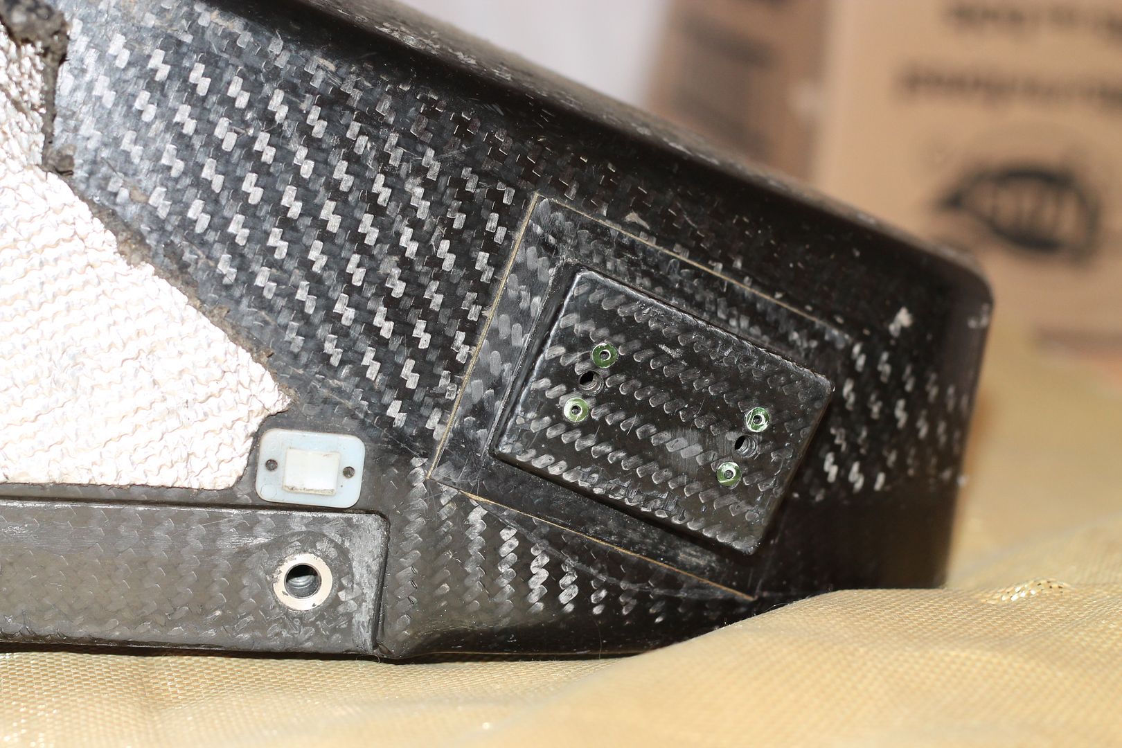
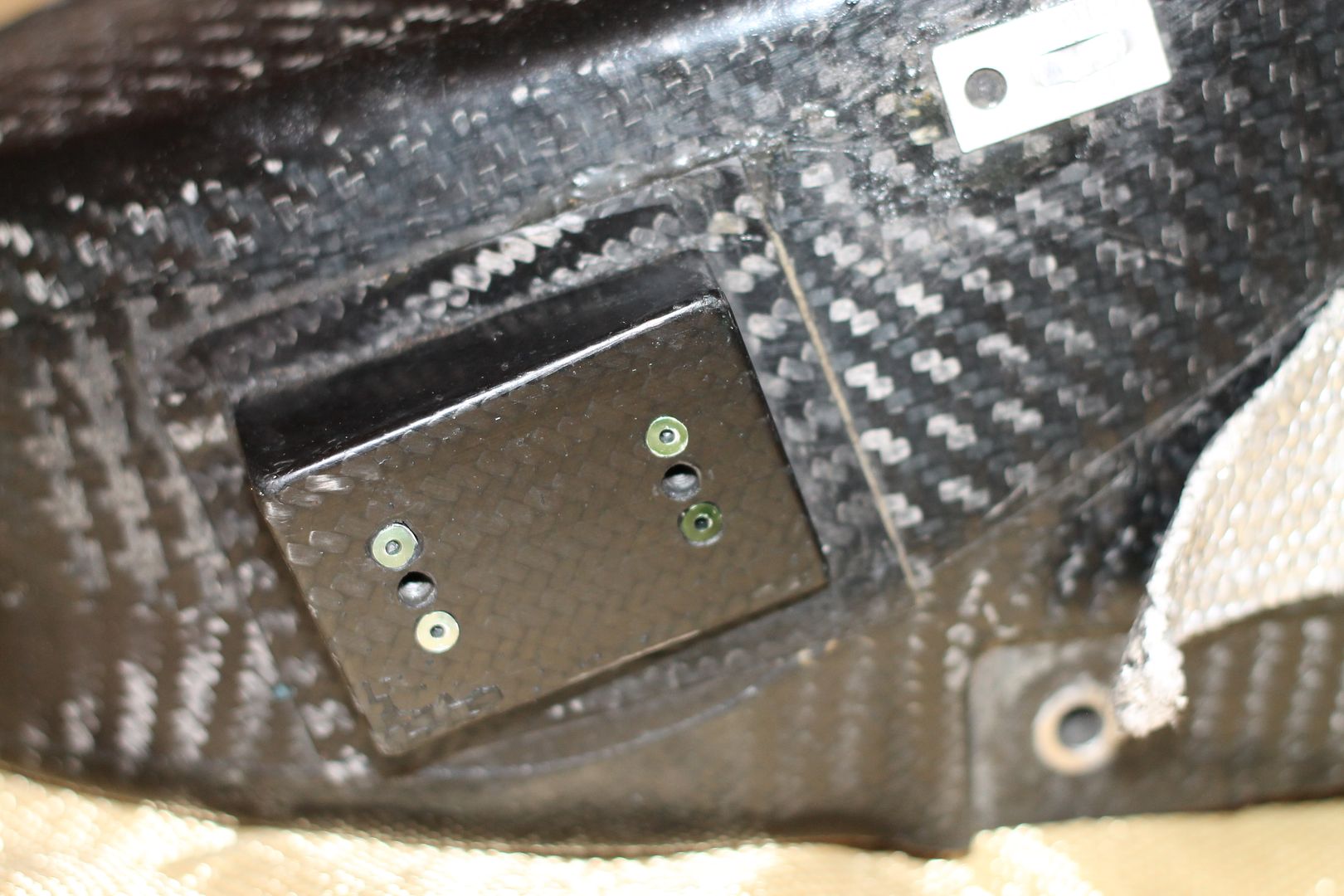
I do know from looking inside it, that the outer layers were laid in first(1mm thick(ish)), that cured, and then the four main hard points for the lower(x4(inserts bonded in. The outer layers were high kevlar content.
Once these were cured, the hard points were drilled, and the inserts fitted.
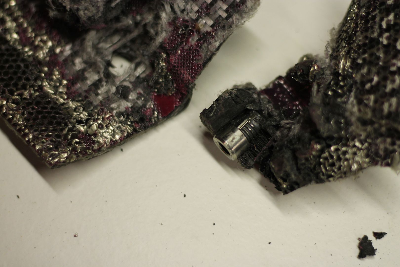
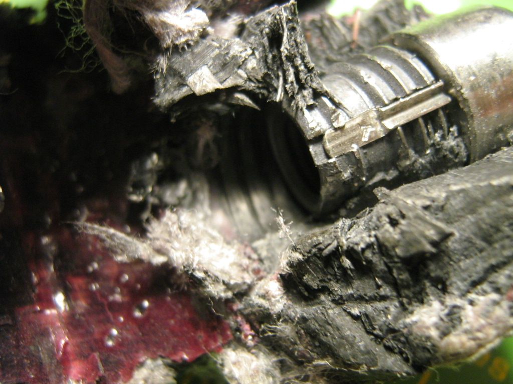
Im sure some form of thread minder was inserted to keep excess epoxy out of the inserts. I know the inserts were fitted before any other internal layers were fitted, as there was small amounts of run off epoxy present in the last most portions of the inserts. This epoxy flowed in there as additional layers and comb was laid up. This run-off epoxy was the same colour as the epoxy used to bond in the first layer of aluminium honeycomb(6mm thick)so I can be certain the inserts were fitted before an internal structure was placed.
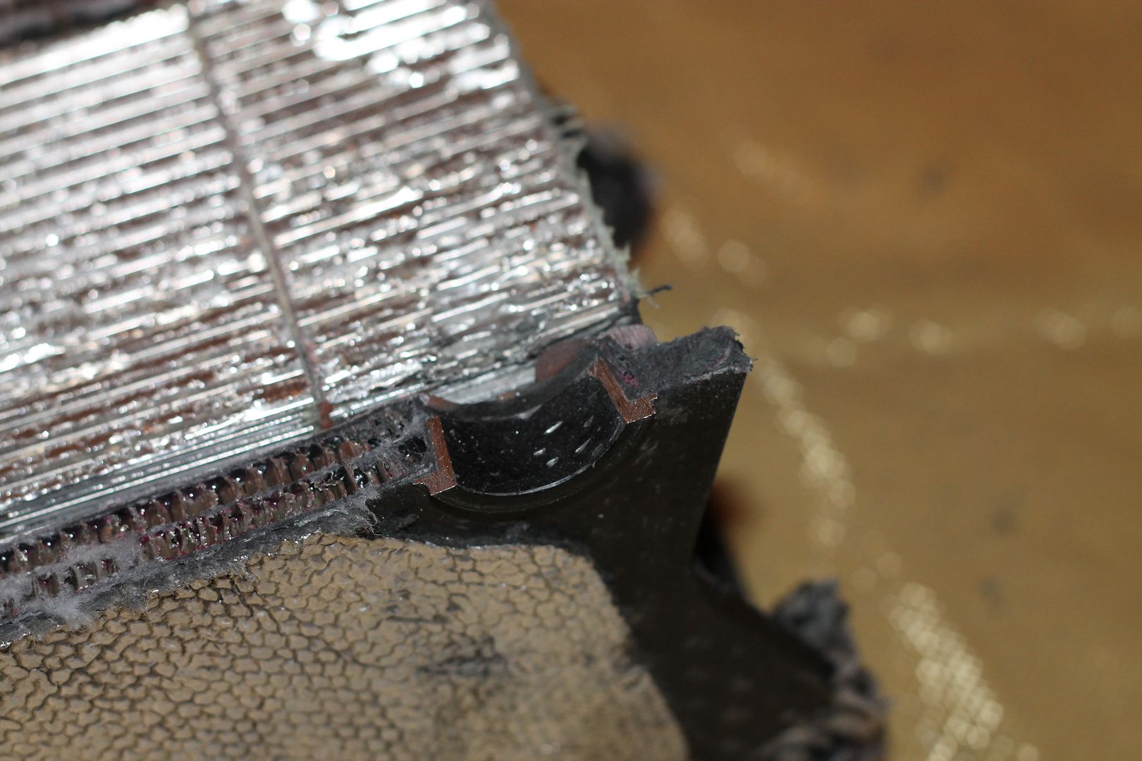
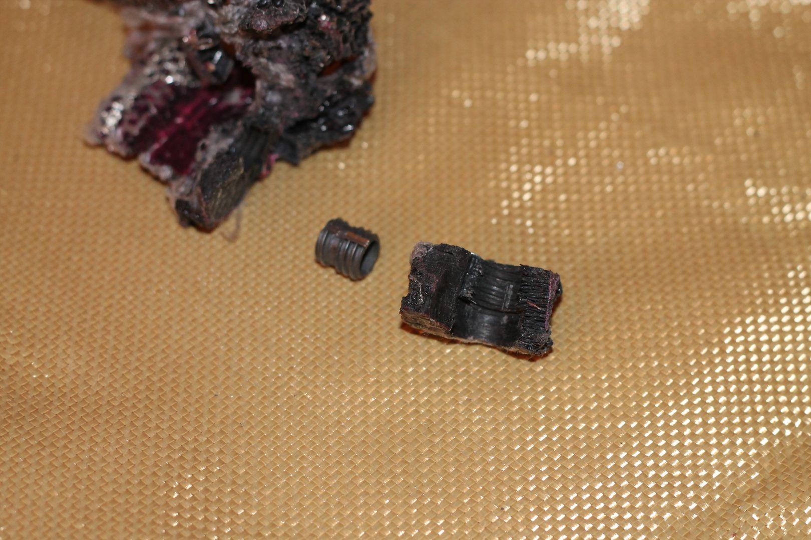
The hard points were 25mm round x 15mm thick, solid sections of carbon composite. They are constructed in a separate operation by stacking dozens of coin shaped fabric on each other until the part is 15mm high. Or, perhaps they were cut from 15mm composite plate.
They are very dense and were belt sanded to match approximately the interior corner radius of the first layers that were placed inside the female tools.
The outer circumferential edges(facing into the part) were also eased with the belt sander. Im guessing to rid high energy areas, and also to make smoothing easier.
Around these hard points was more epoxy, filleting them in nicely to their surroundings.
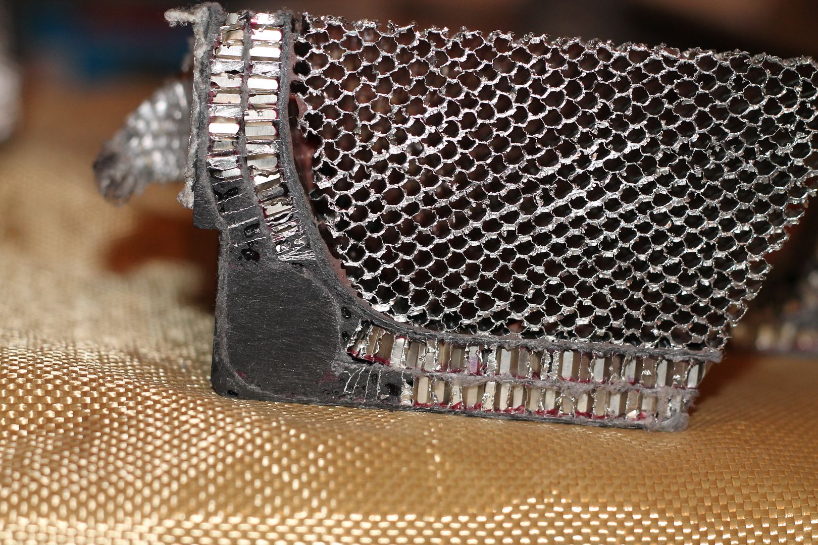
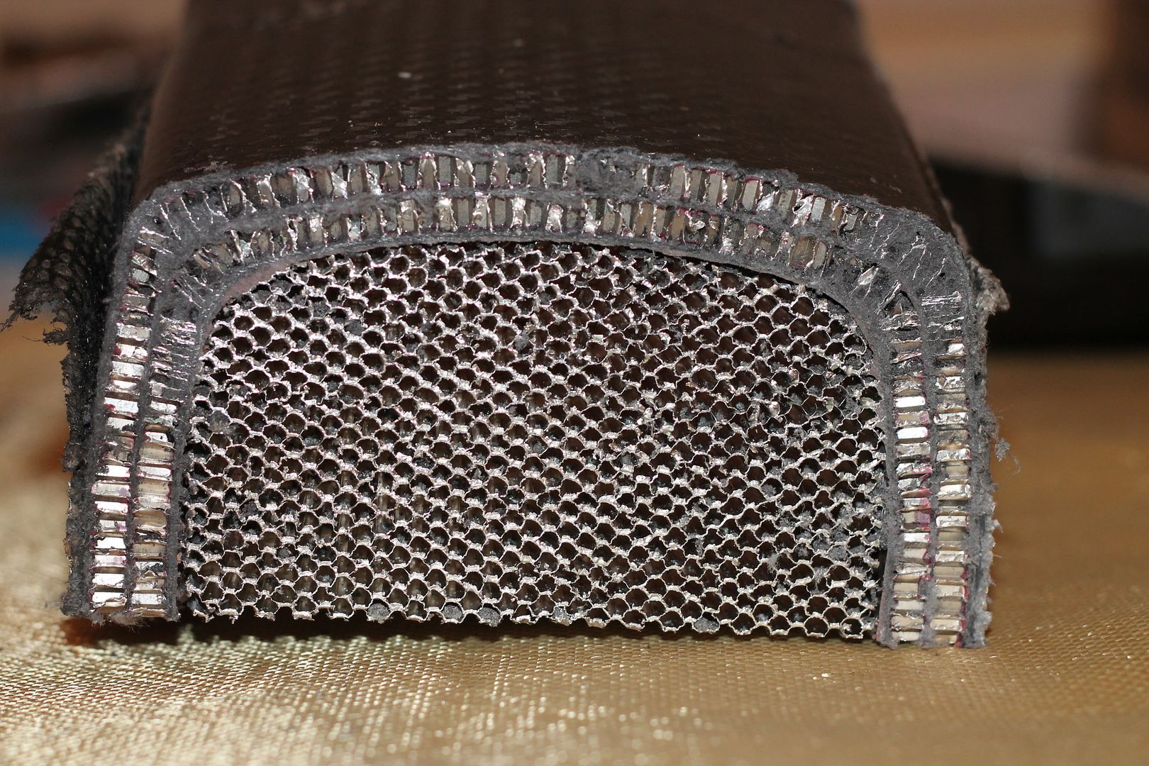
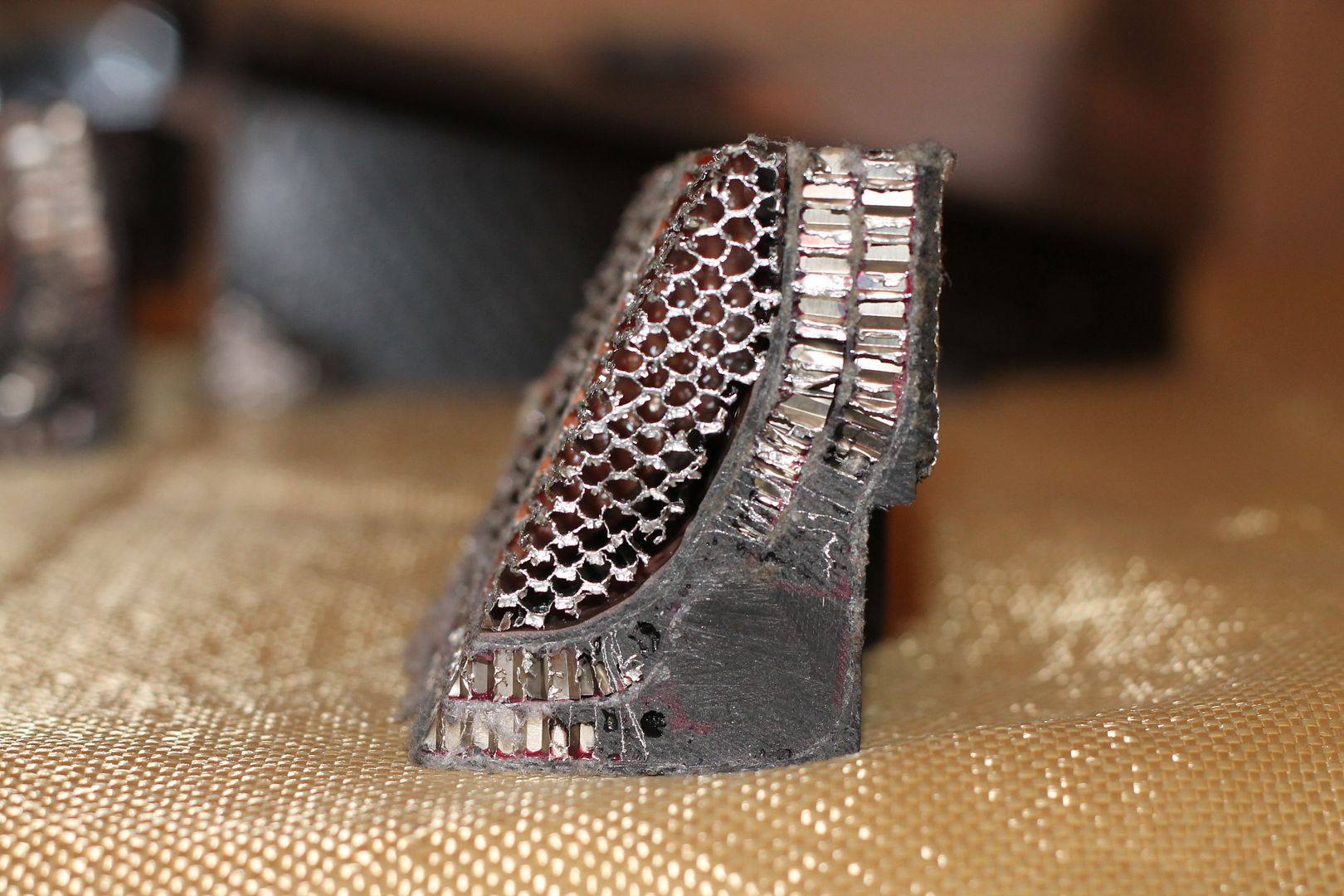
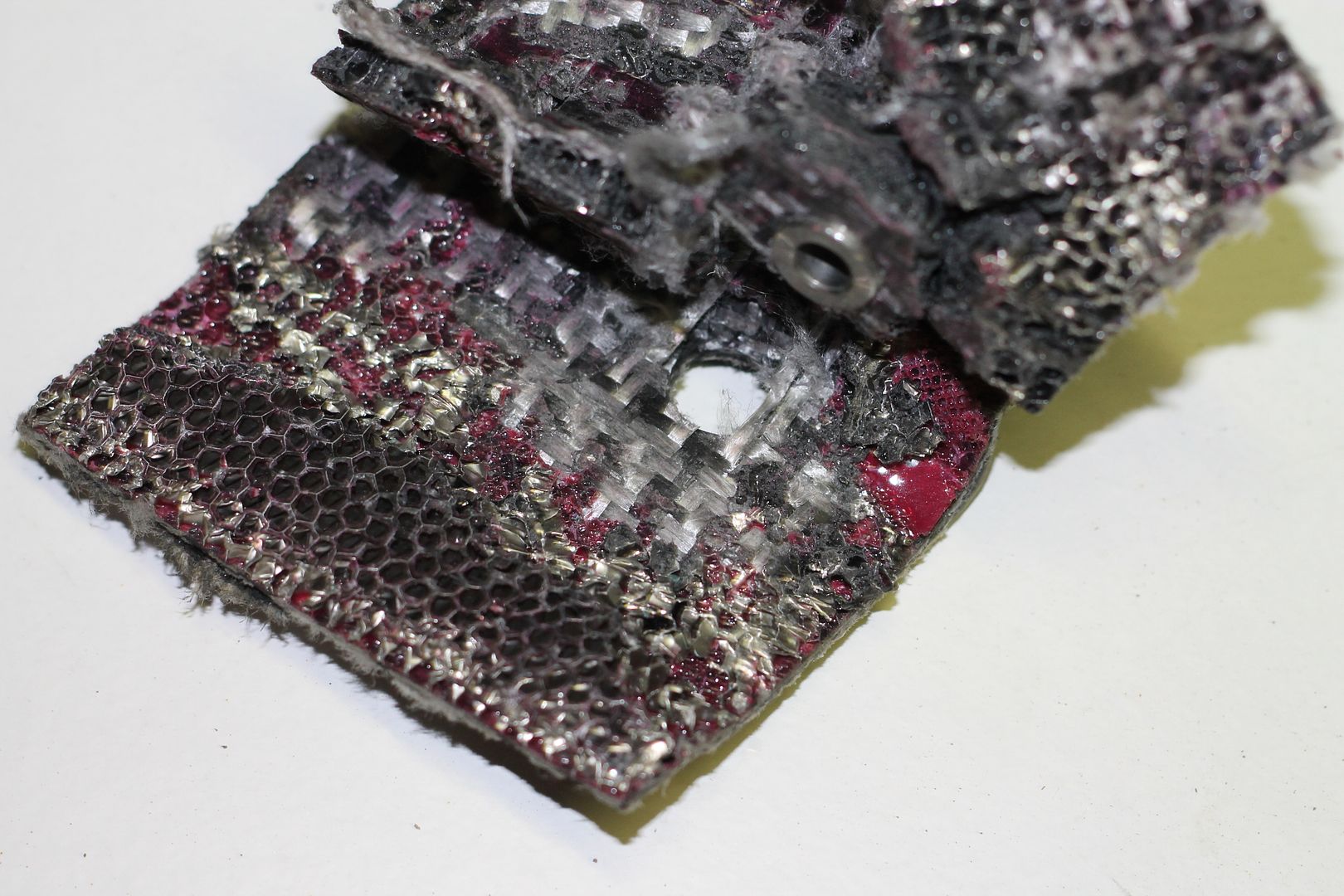
The interior was wetted up, and the first layer of 6mm Al comb was placed down.
It was cut pretty well to fit, and was cut around where the hard points had just been bonded.
More epoxy, this time with filler added, possibly hollow glass spheres was filled around the hard points, further bonding them in to their surroundings, some of this epoxy can be seem in the areas of comb surrounding the hard points.
In some of the images, the cross-section of the hard points will appear solid tube like, this is not the case, it is just the way the saw has displayed them, and their cross-sectional profile at the point.
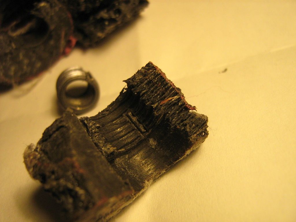
Once the first comb layer was fitted, there then was a .5mm layer installed ontop.
This layer measures half the thickness of the first external lay up mentioned above.
It is also of high kevlar content, I do see carbon in there too, so a hybrid weave fabric.
This layer covered the first comb layer, and the hardpoints/epoxy filler.
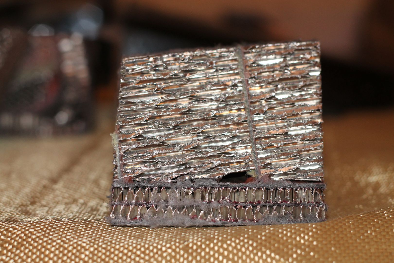
Over this, were laid last interior layers including another comb layer, same thickness as the outer first lay up, 1mm thick, the comb also 6mm. Im guessing at this stage, epoxy hard point filler, all comb layers, and last interior layer were vacuum bagged to all conform neatly to eachother inside the structure, and to the outer first cured layup. The bag being inserted down into the whole assembly. Inside out vac bagging if you like.
We know from the way that the inserts were fitted(see above) that the outer and first lay up had been cured prior to the internal structure being built in, so whether or not the part was left in the tool the entire time is debatable. Perhaps for lay up it was removed for ease of part handling, then refitted for vacuuming.
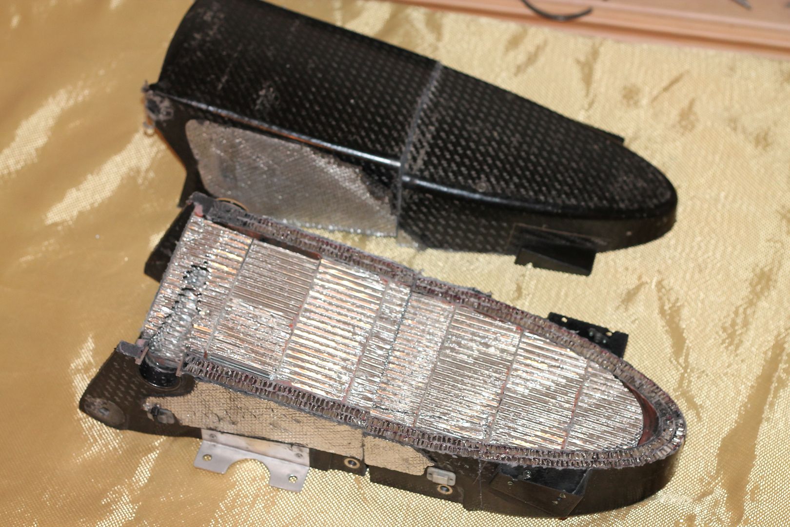
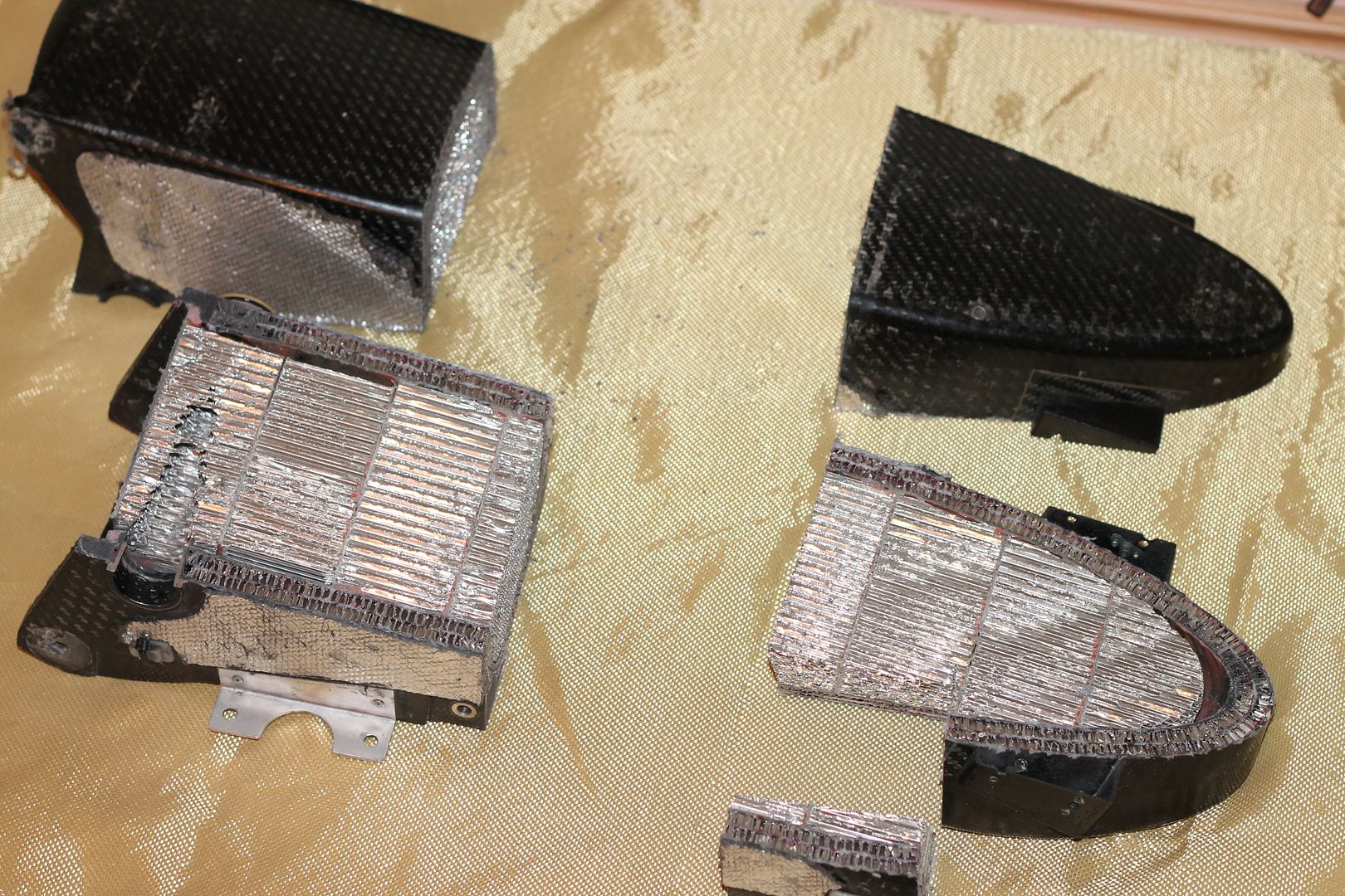
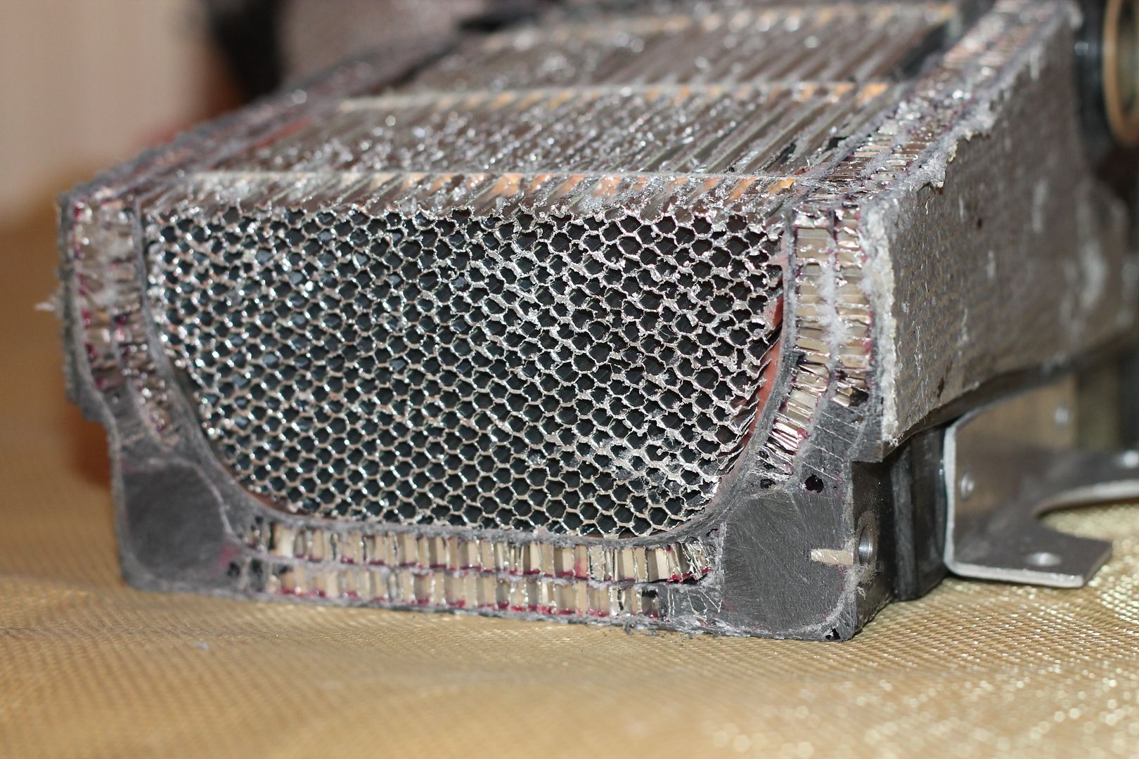
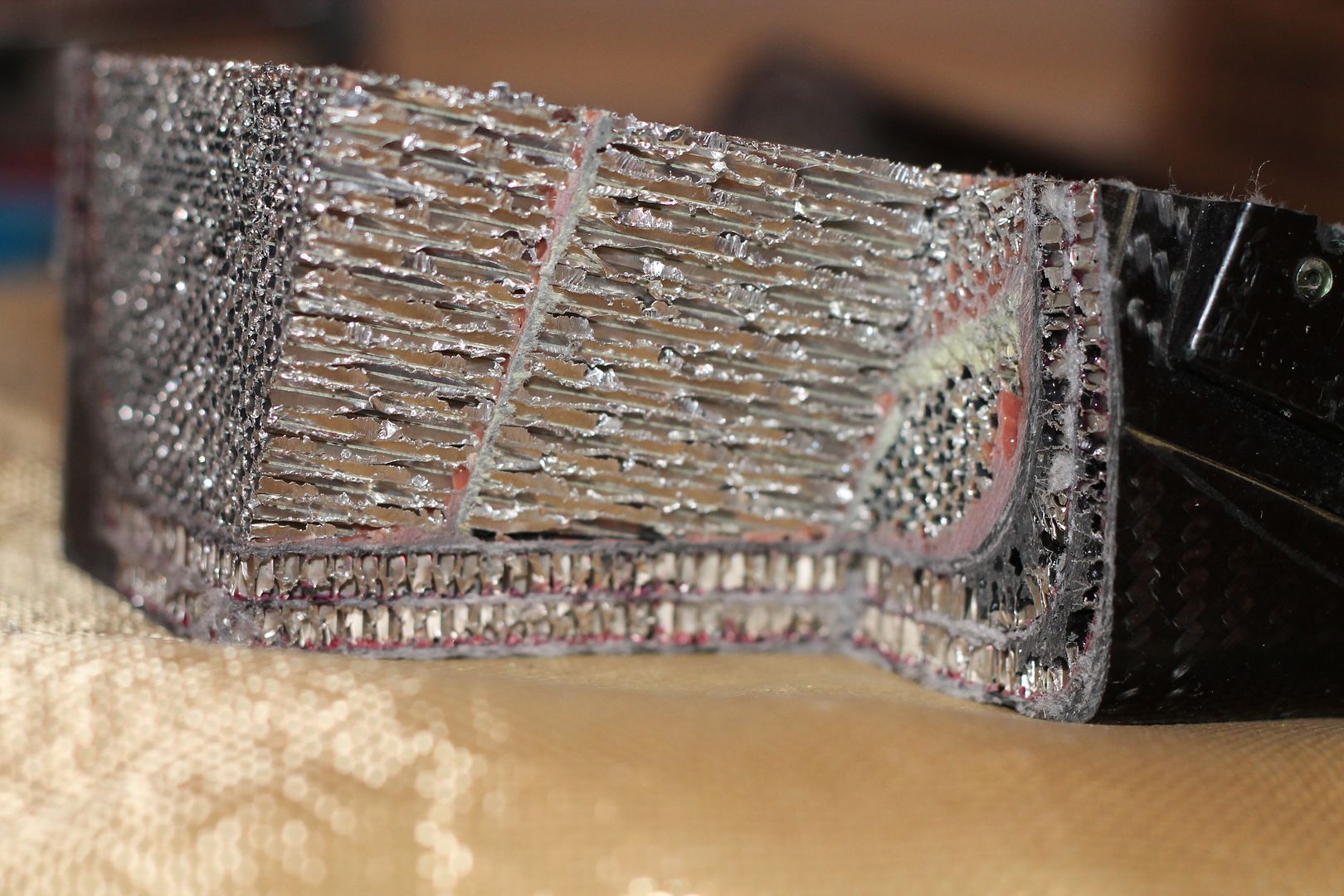
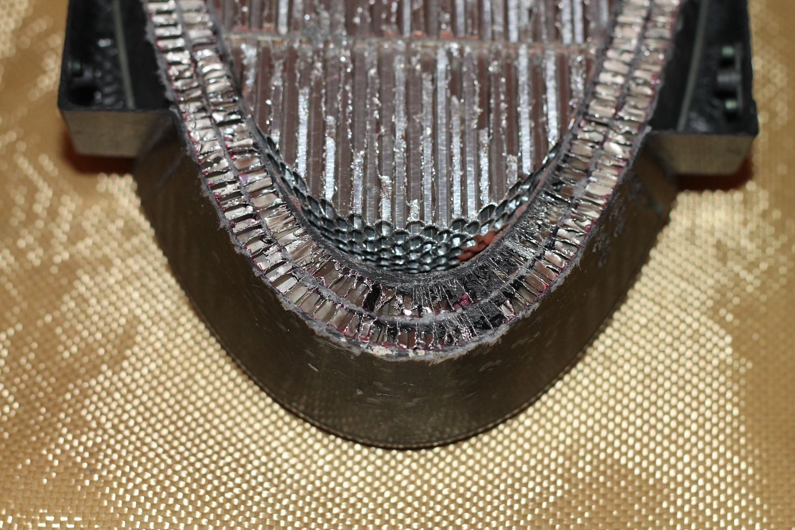
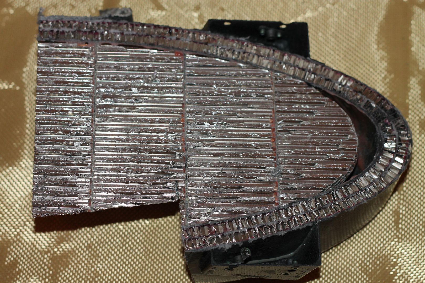
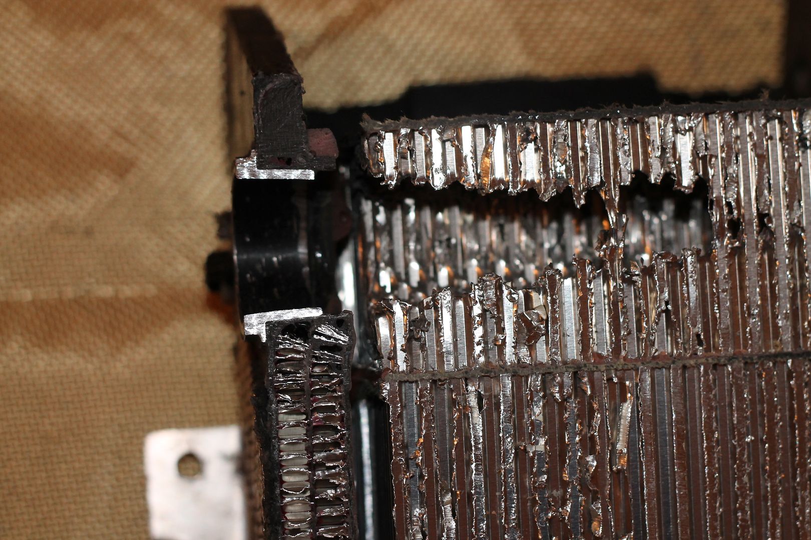
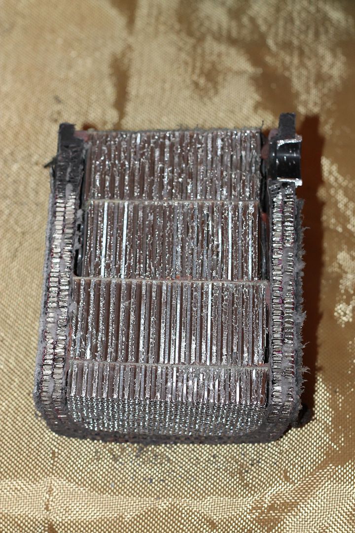
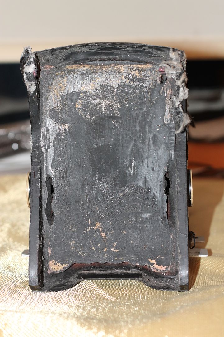
Once all the internal layers were cured, the bag was removed and the 50mm thick comb sections and partitions were added.
These were all done in the one hit, and done wet lay.
They are 1mm thick and there is seven in total including the last, outer thrust cap panel, adjacent to the gearbox.
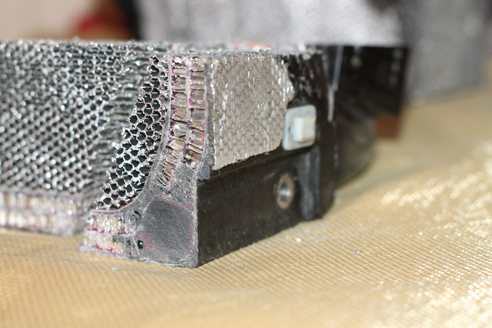
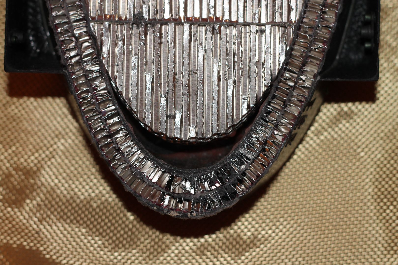
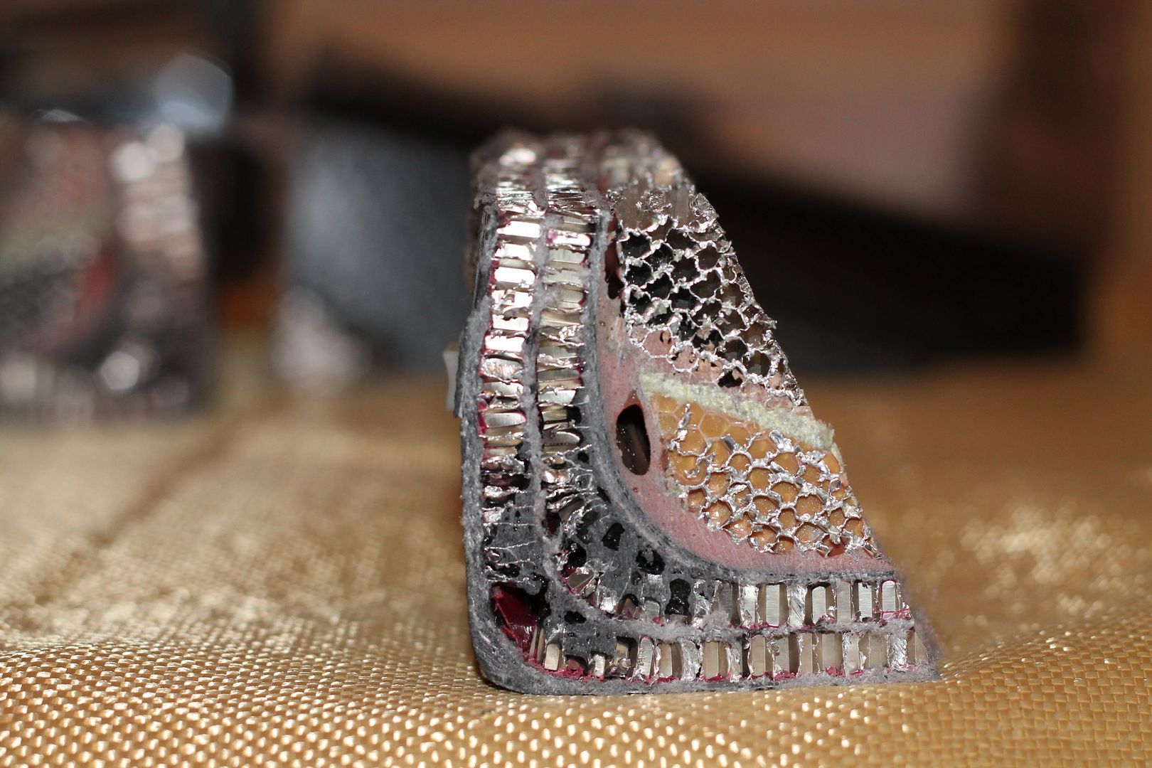
Interestingly, the first section of comb is kept back 10mm from the rear(end tip) wall of the crash structure. Looks like the nose and walls take some of the energy before it starts to progress on into the 50mm comb structures.
The comb is a good fit to the inner walls of structure, as are the kevlar partitions. The first rear most nose comb is fitted, and the rest are stacked onto it. The rear most comb locates via interference fit with the walls, keeping the nose 10mm as mentioned from the end wall.
The kevlar partitions are filleted where they meet the structure walls as the operator progresses. The interior has a heavy coat of epoxy applied also.
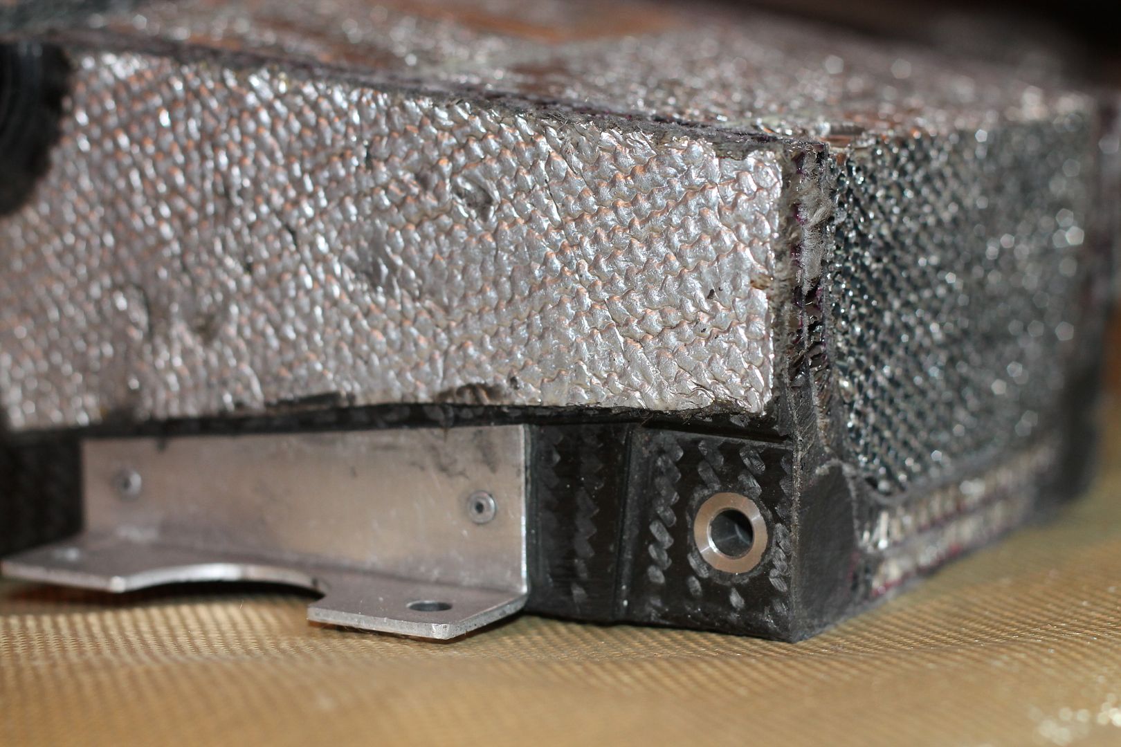
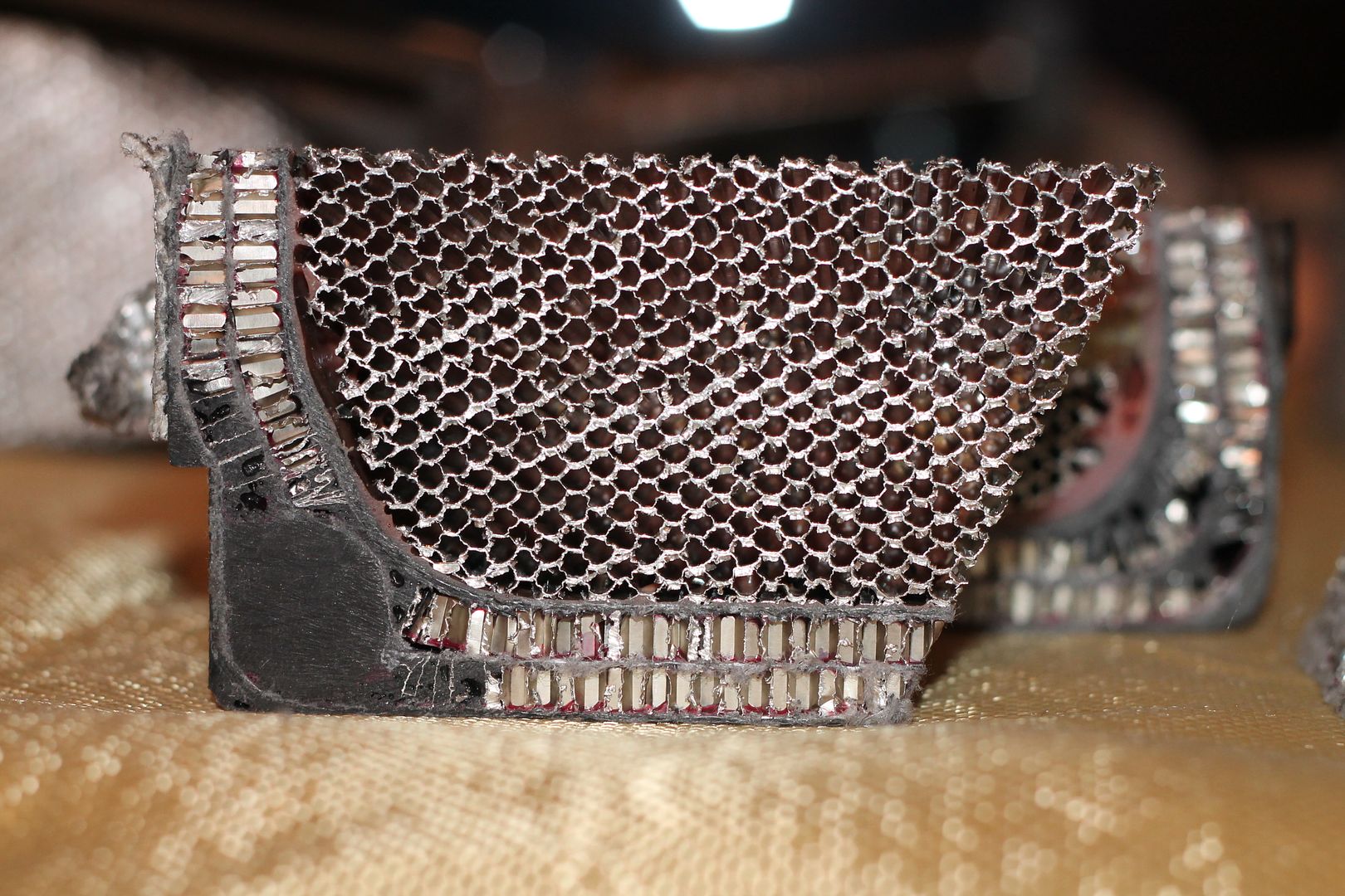
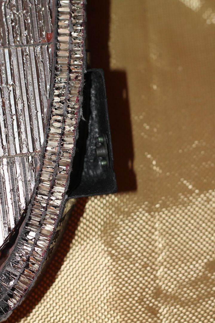
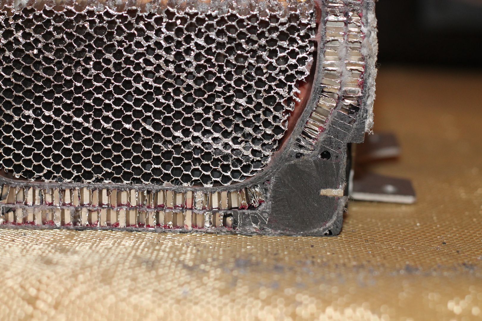
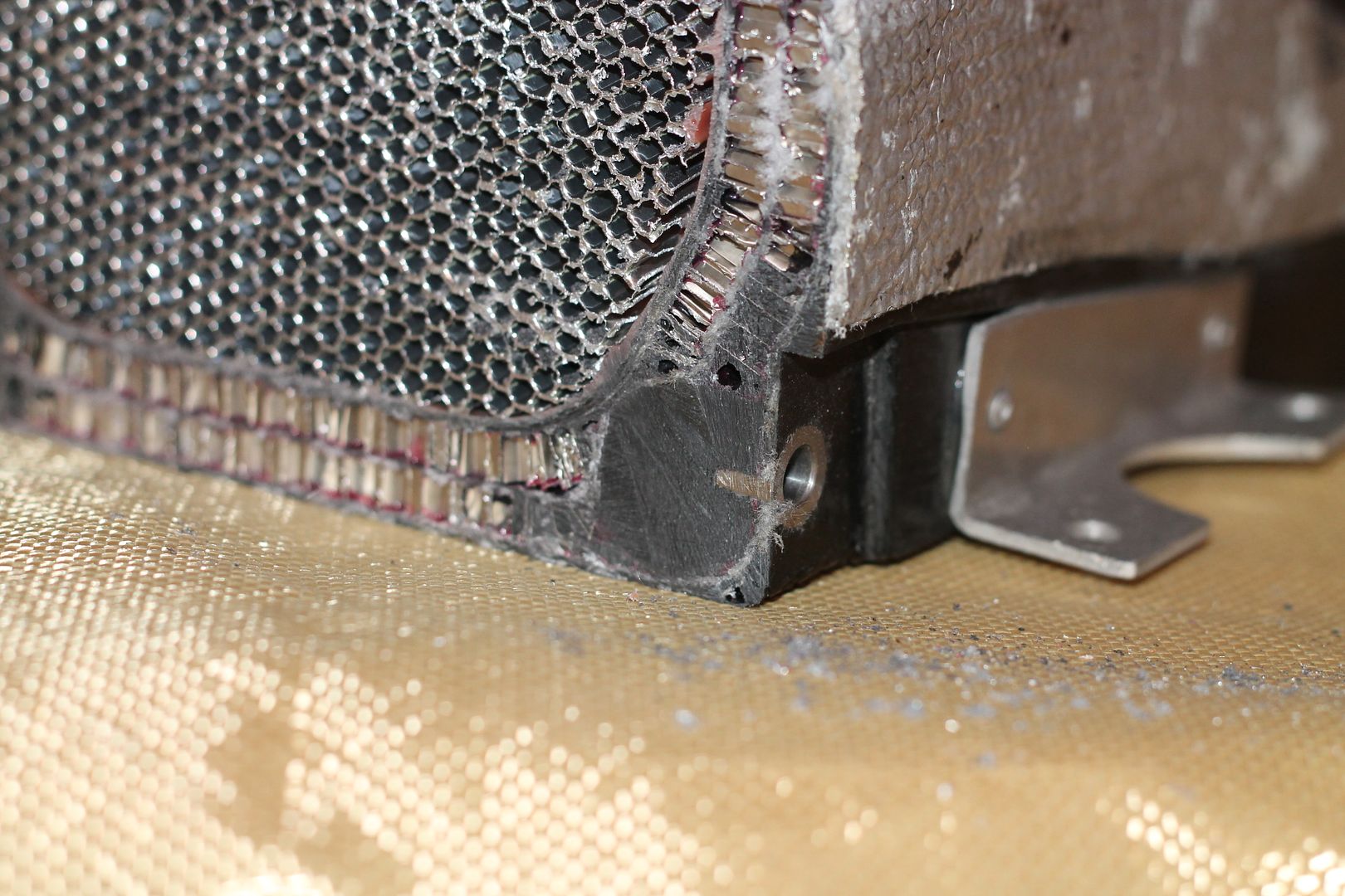
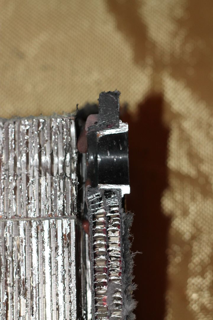
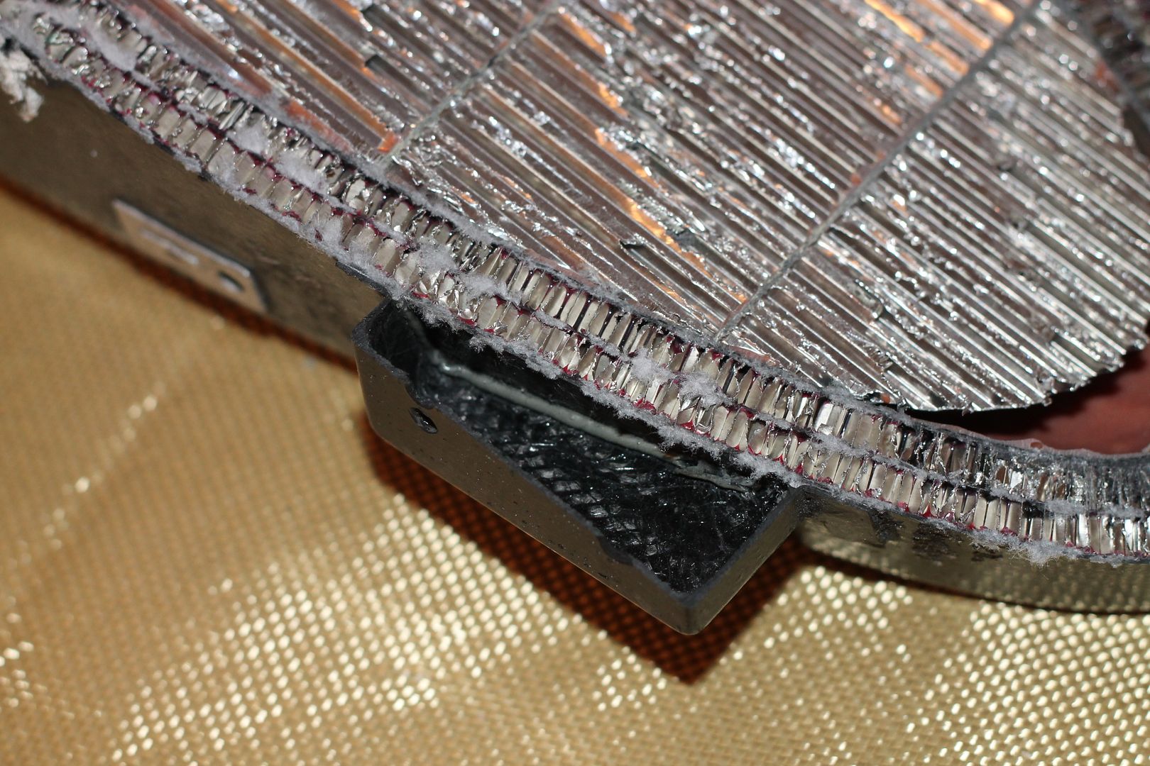
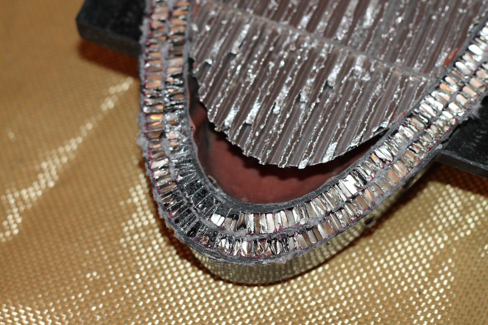
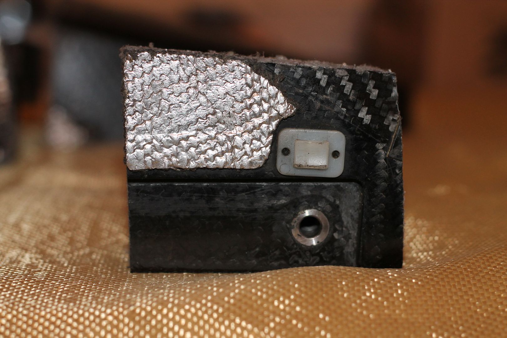
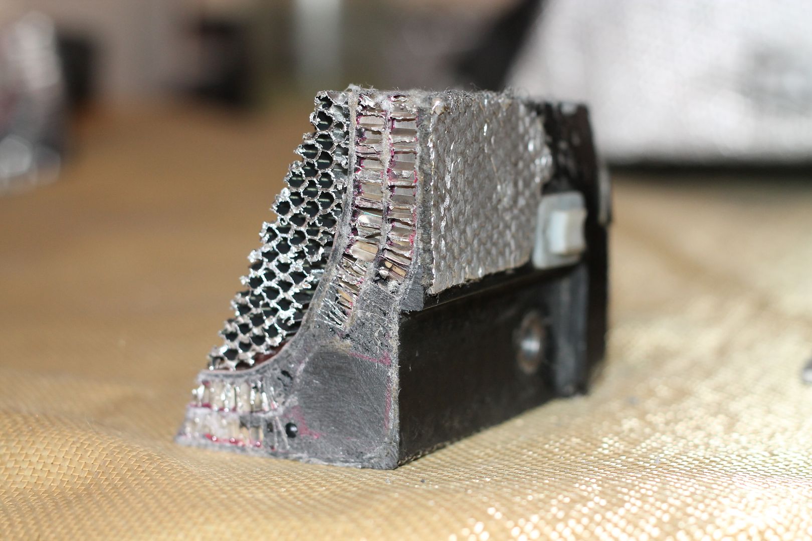
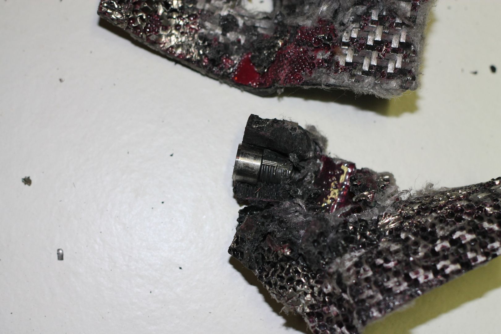
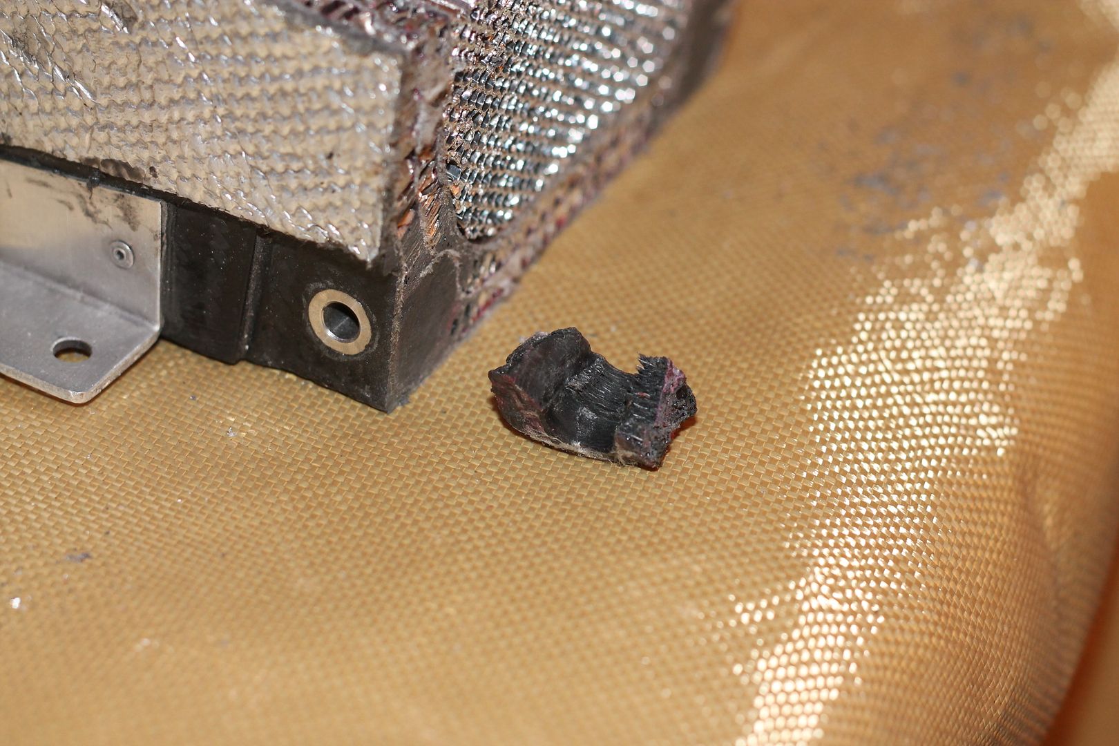
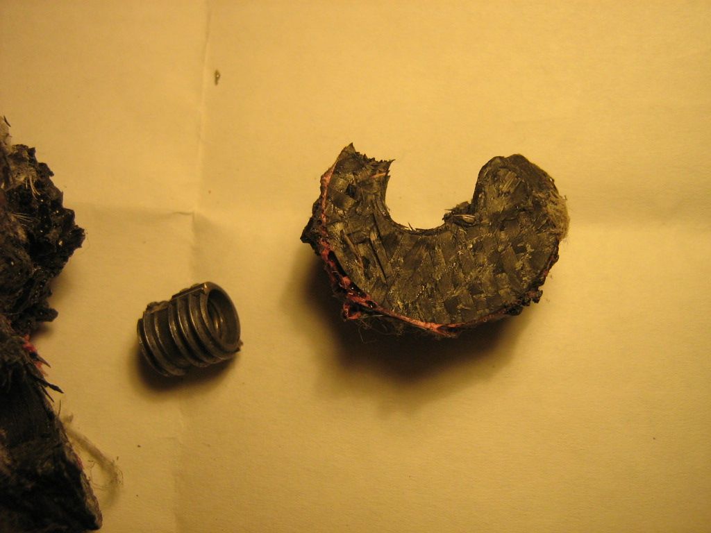
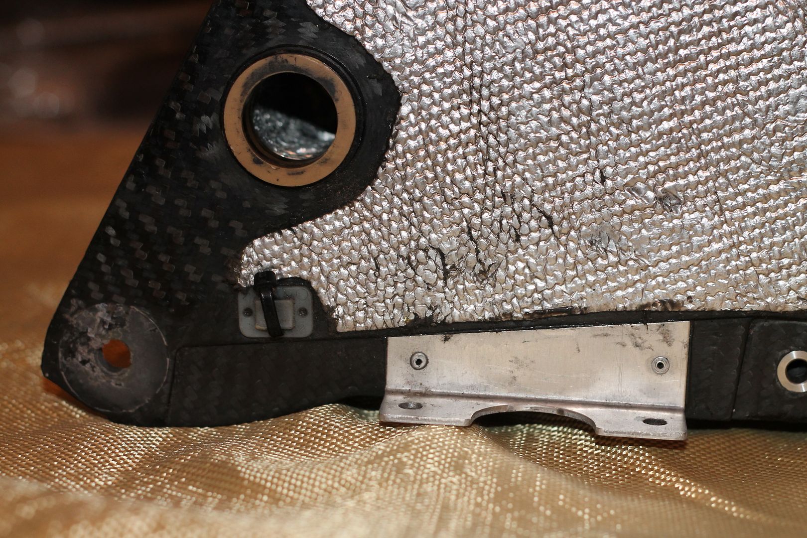
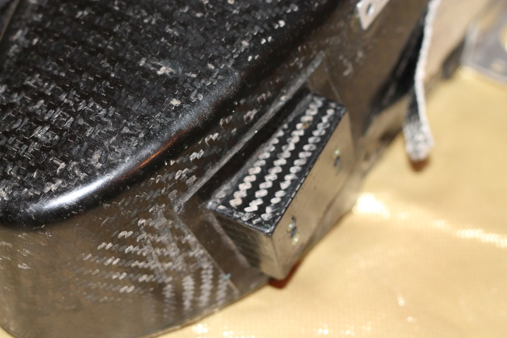
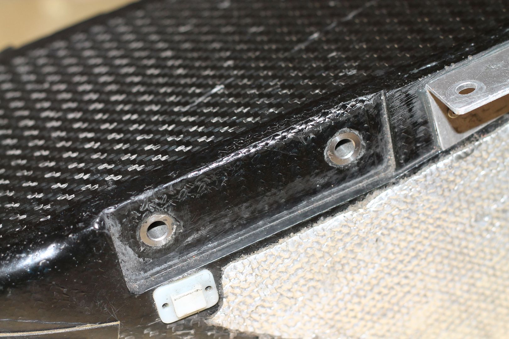
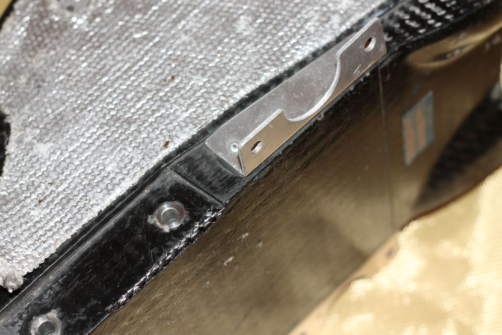
The end of the structure where it attaches to the rear of the car is also mounted with hardpoints inside the structure.
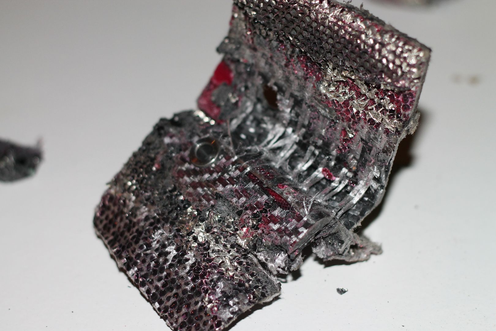
This time, 8mm composite plate is used. Two strips down either side run from top to bottom. These are shaped on the other edges to match mating profile.
These strips get bonded to the first layup as with the first layer of 6mm comb. It is also bonded into the first comb layer with filled epoxy.
This solid composite strip closes off the edge of the first comb layer.
The .5mm later ontop of the first comb stops at the interior rear of strip.
The second comb is placed and cut at the same place the first comb layer stops, at the rear of strip.
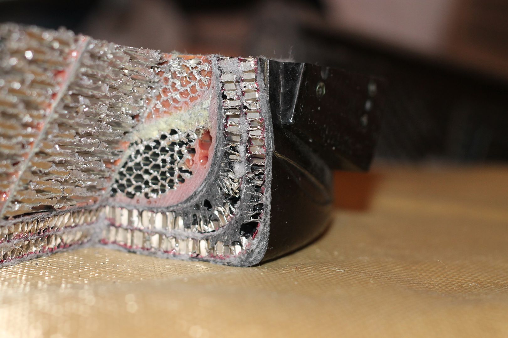
A 45 degree fillet of filled epoxy is then formed at the end of the second comb layer and is filleted down onto the solid composite strip.
The final interior 1mm layer is then laid down over the second comb layer and covers this 45 degree fillet, and ends at the out profile of the composite strip.
This can be seen if you look carefully at the pictures, as can everything else mentioned.
One last thing to look out for, the second last partition(gearbox end) does not touch the interior walls.
The partitions may look angled from the photos, but they are 90 degrees to the road surface when the structure is fitted to the car.
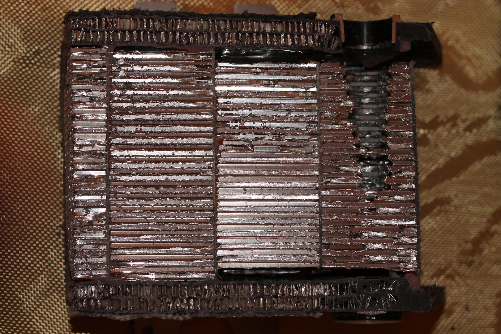
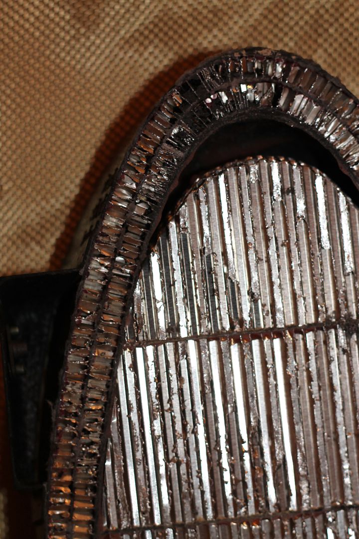
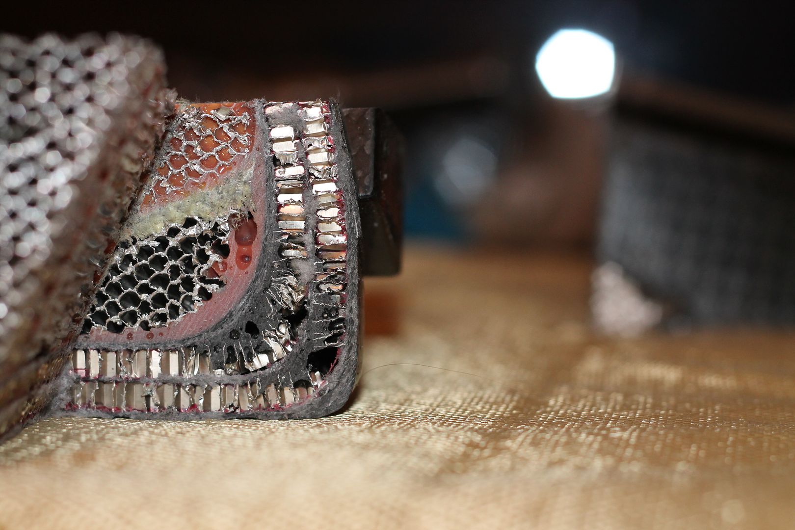
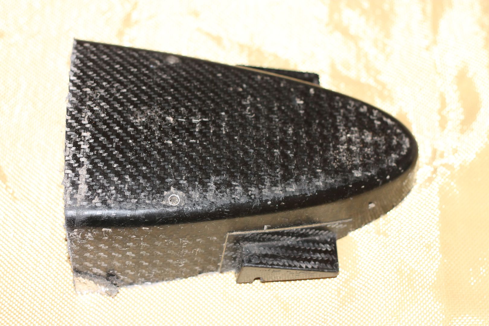
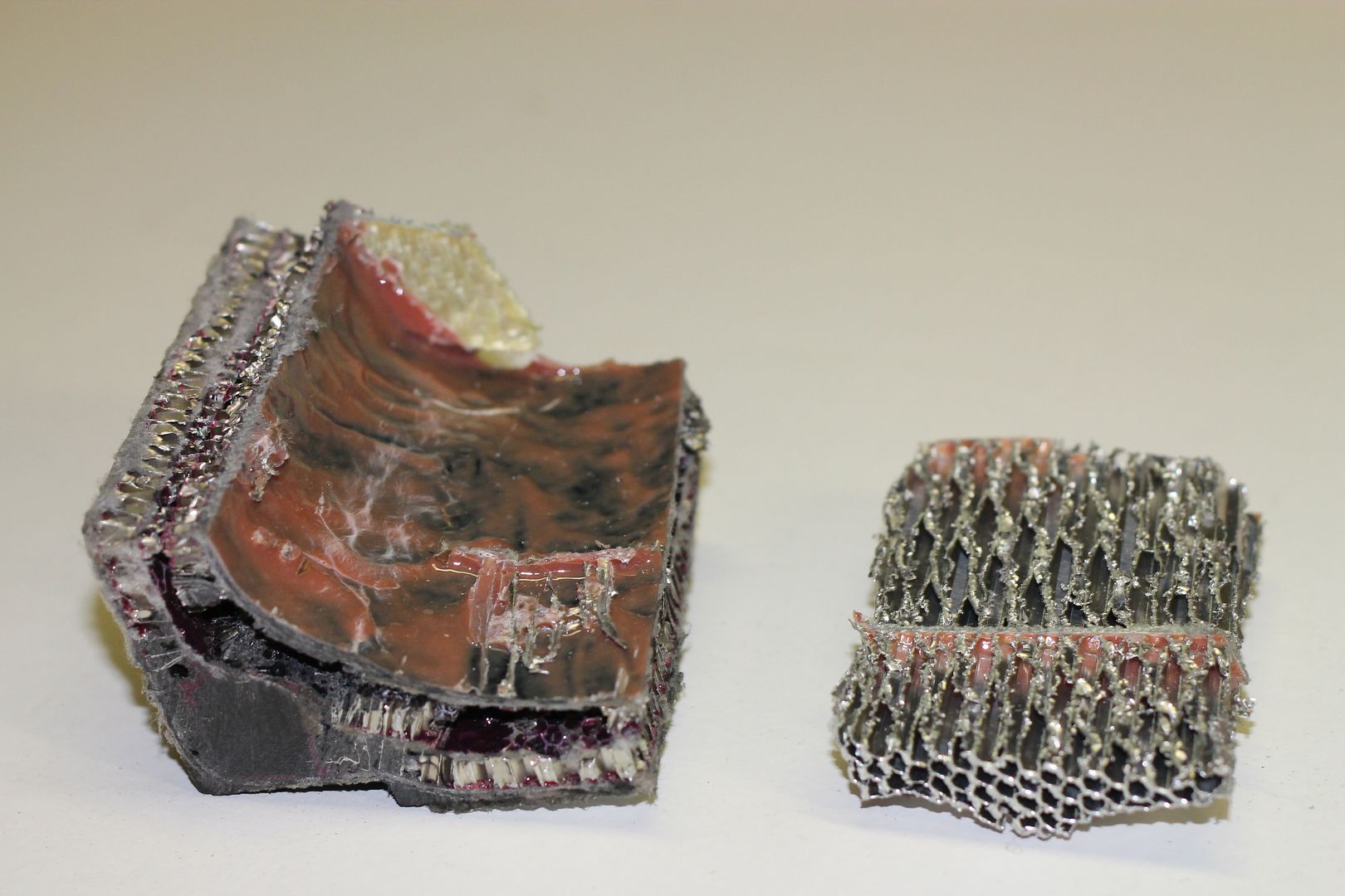
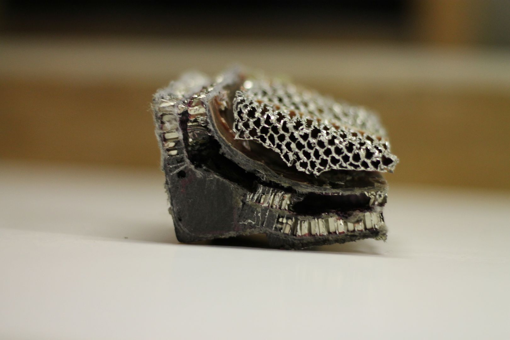
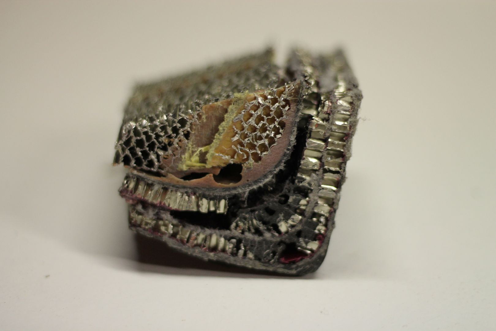
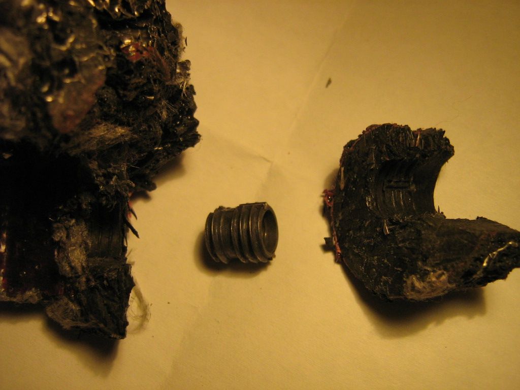
The pictures,
The structure before cutting,
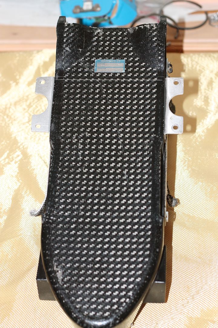
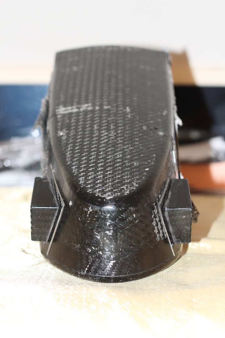
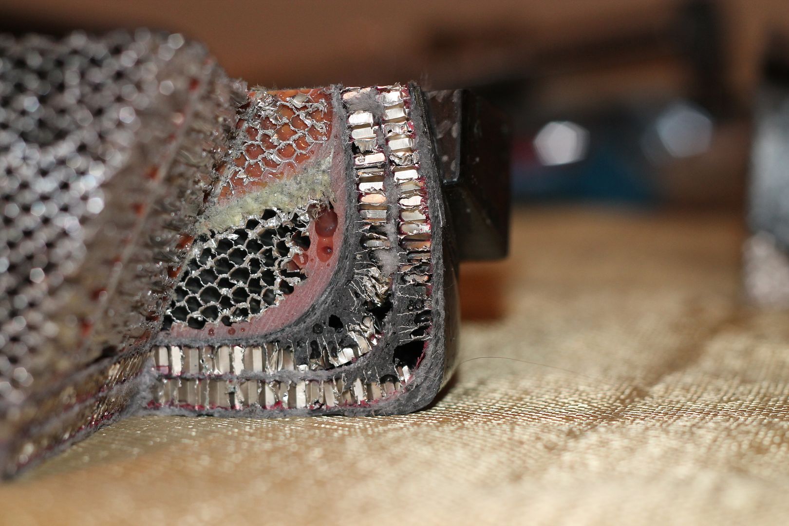
The cut sections next,