Carbon Fibre pushrod, a closer look

Here are our CFD links and discussions about aerodynamics, suspension, driver safety and tyres. Please stick to F1 on this forum.
Brian.G
Brian.G
334
Joined: 10 Dec 2010, 23:52
Location: Ireland

Carbon Fibre pushrod, a closer look

Post

Hello again folks, I carried out this for my own research, and so decided to share.

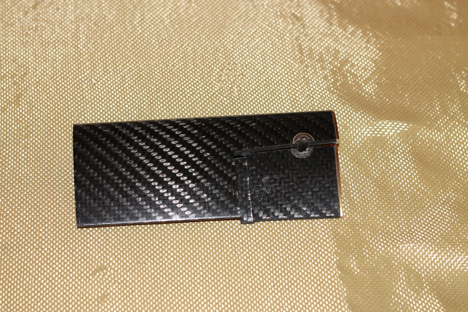
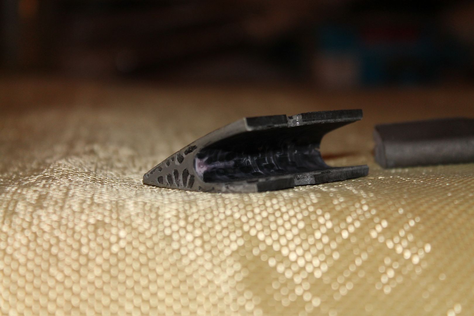
Its a common style of pushrod, and so too is its construction.

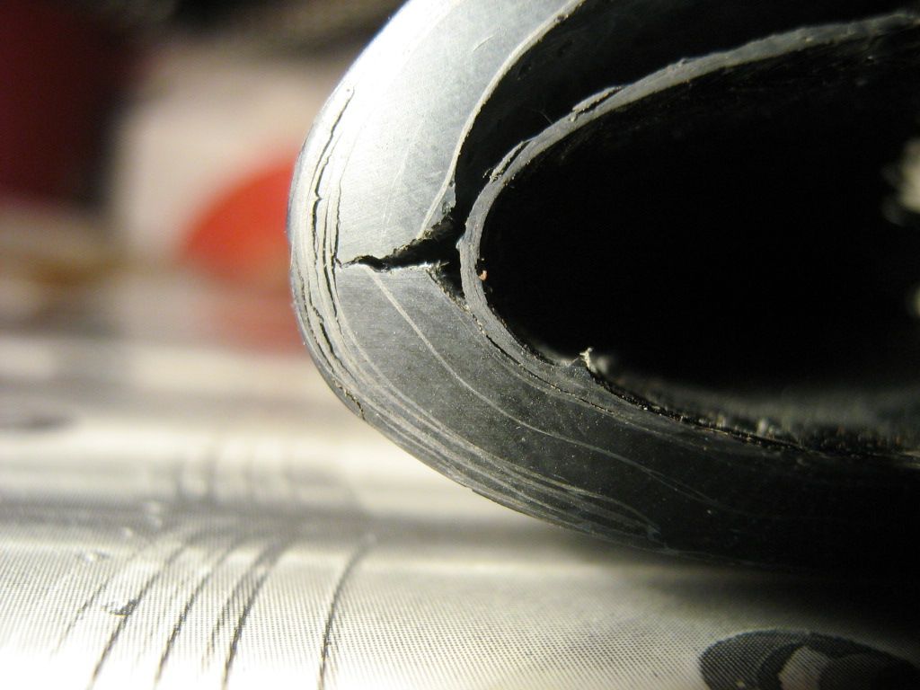
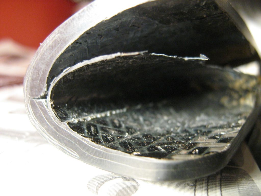
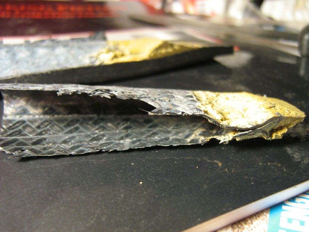
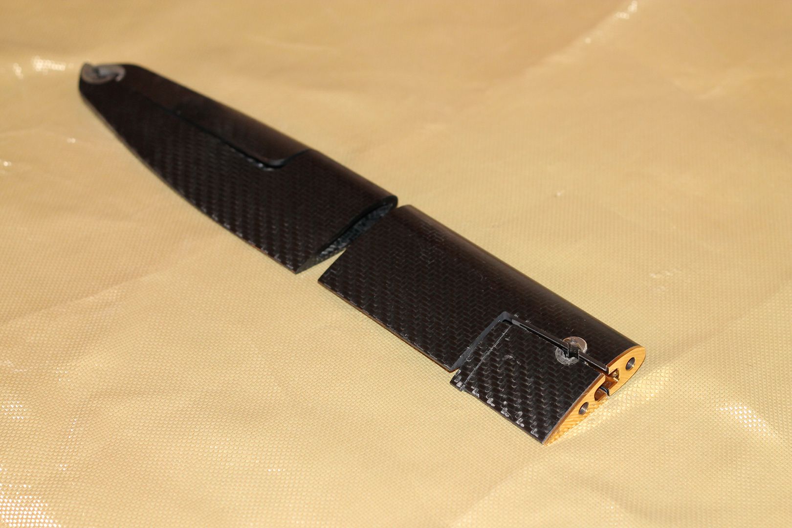
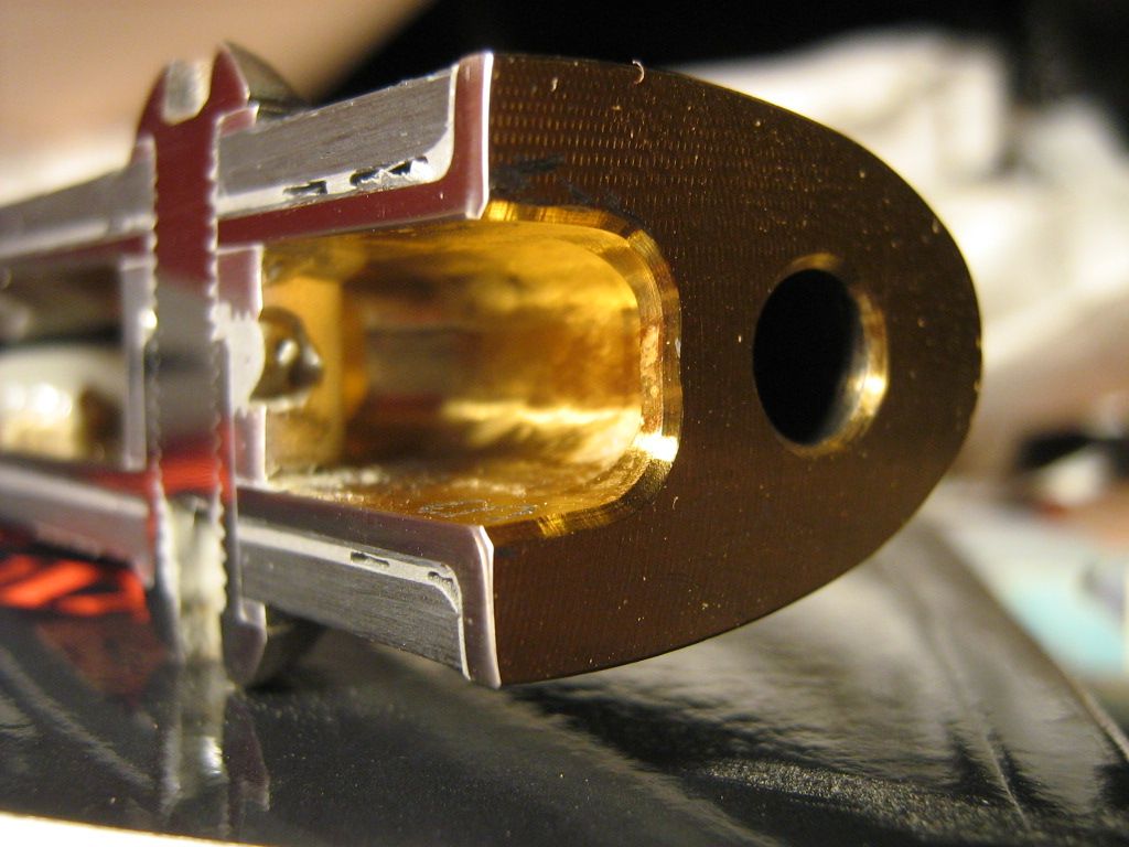
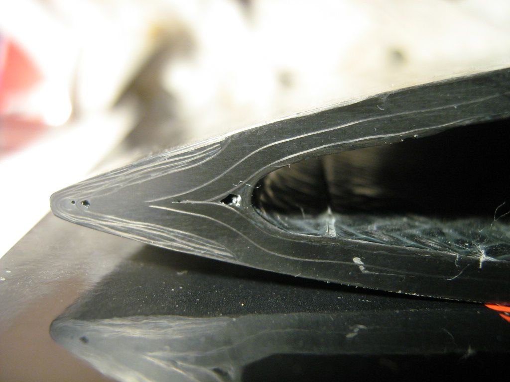
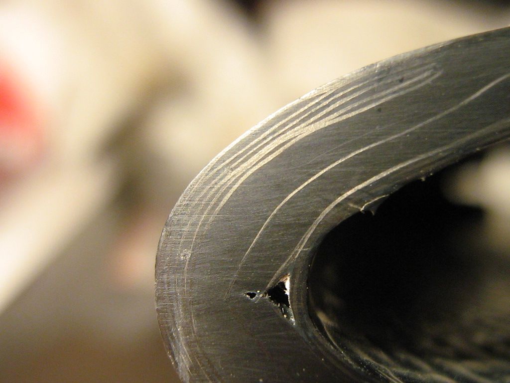
The pushrod is aero in cross-section where the gold titanium insert is bonded in and it tapers in cross-section towards the opposite end where the single ferruled and washered hole lies. Both top and bottom sections of profile converge towards the last 100mm where they become one.

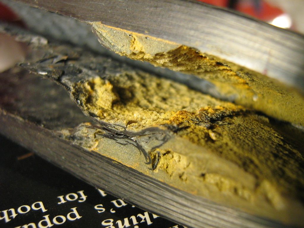
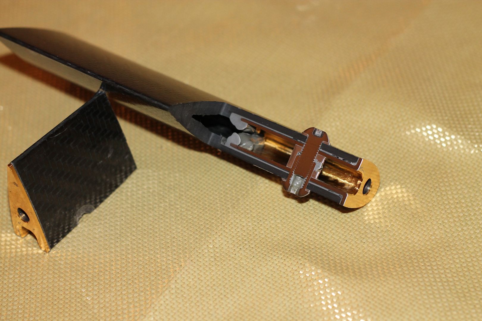
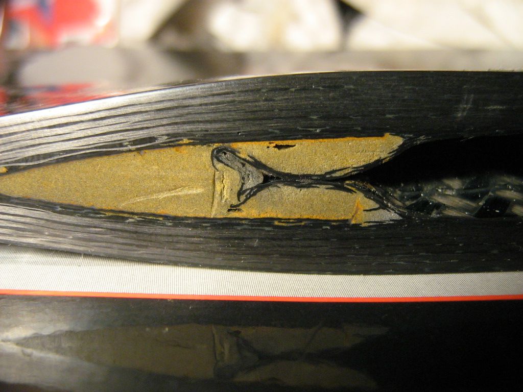
The main area I wanted to study inside the pushrod was where the ti insert gets bonded in. I wanted to see the bolt securing arrangement, the glue films, and also if the interior of the pushrod had been prepared in any way prior to insert installation.
I also wanted to have a general closer look at the pushrods cross-sectional construction. From general interior, to the carbon fibre wall layer orientation.

The pushrod measures around 340mm x 65mm x 19mm.

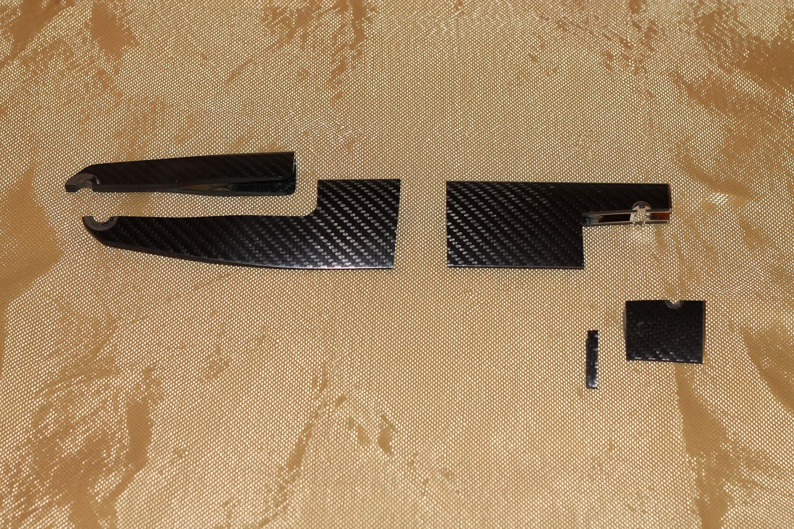
The pictures below show how I sectioned it to display various areas I wanted a closer look at.

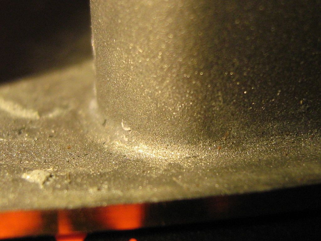
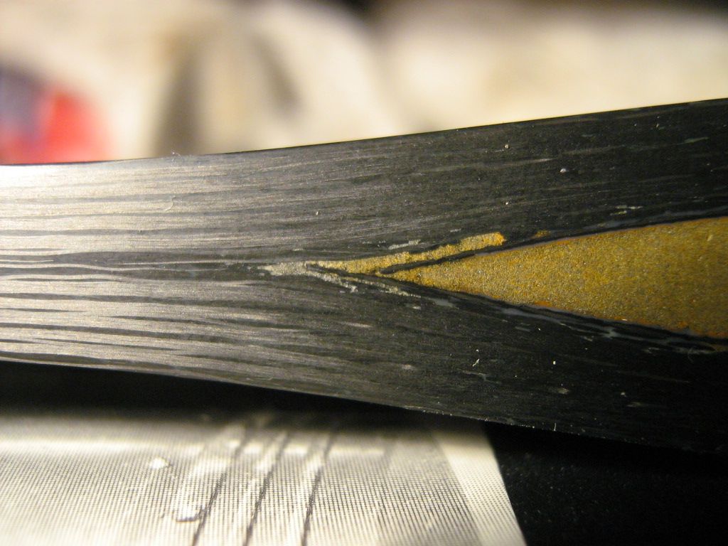
The titanium insert itself features yellow titanium nitrate(TiN) coating on all surfaces excluding the bond surfaces. These have been grit blasted after coating to improve mechanical grip, since TiN is low friction, grit blasting is important in bond areas.
Titanium nitrate coating eliminates galling, fretting, microwelding, and corrosion seizing so it is a useful process where such parts are concerned. Anti gall being important for threaded holes. This coating is also three times harder than chrome.
The coating is also extremely thin at around 3µm, so doesn't really effect dimensional accuracy.
Im sure you have all seen, or used gold coloured drill bits. This is the same coating, but instead used on an alloy steel in the case of drills. Its used for the above reasons.
Titanium Nitride (TiN) is the most common PVD(Physical Vapour Deposition) hard coating in use today where precision parts are concerned.

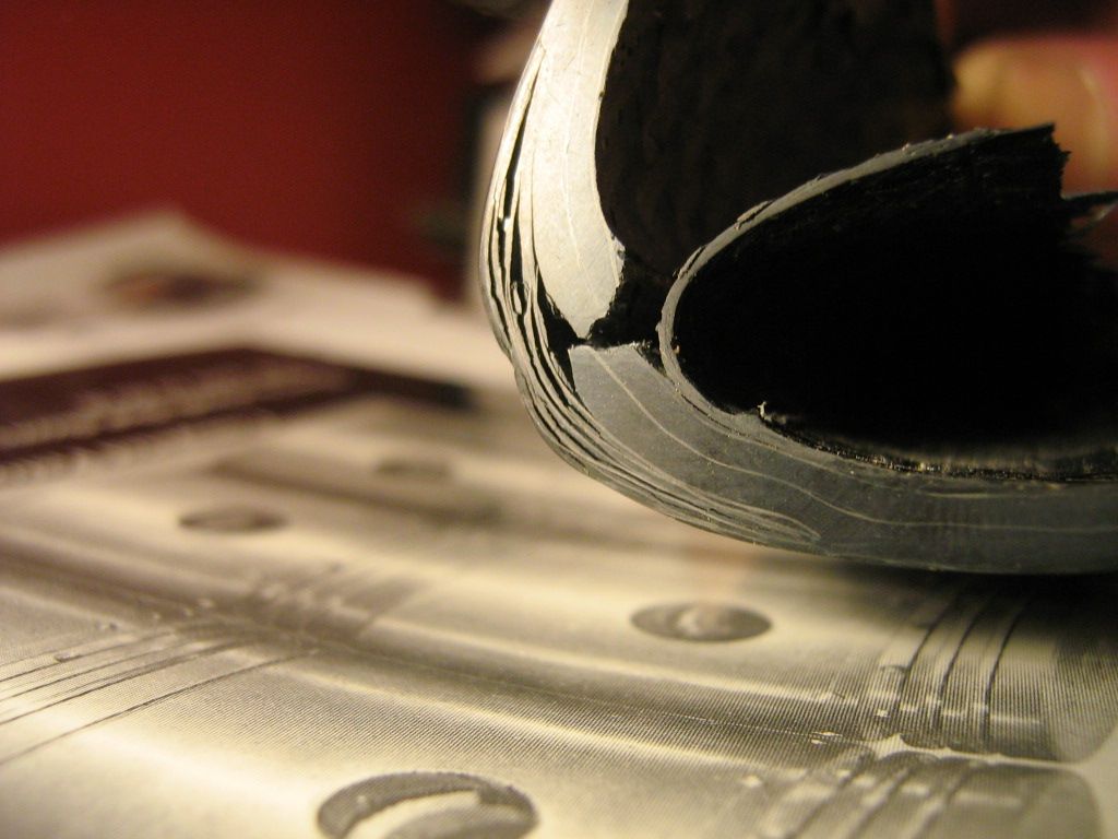
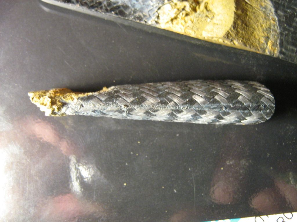
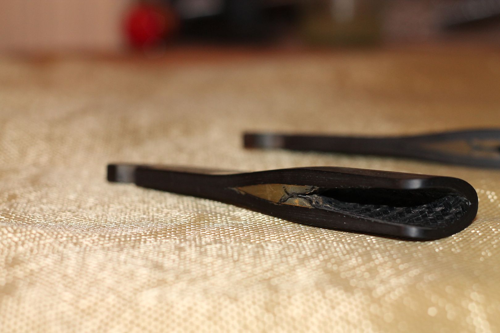
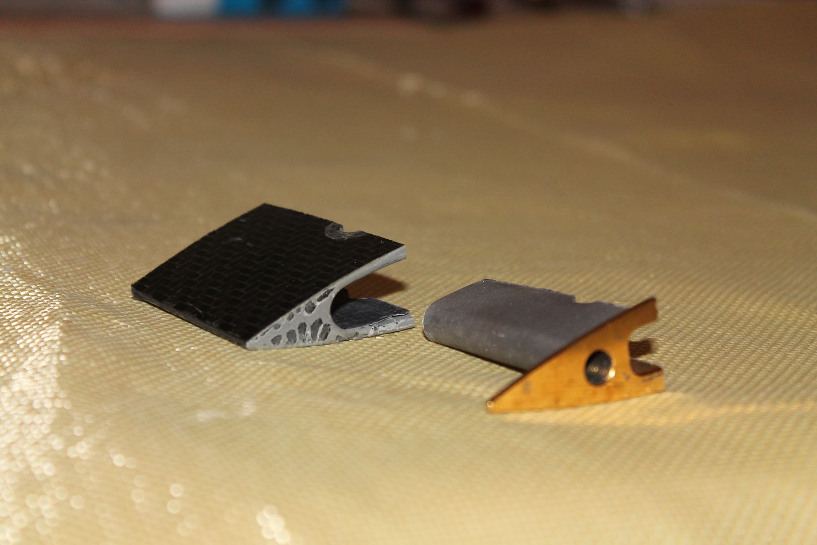
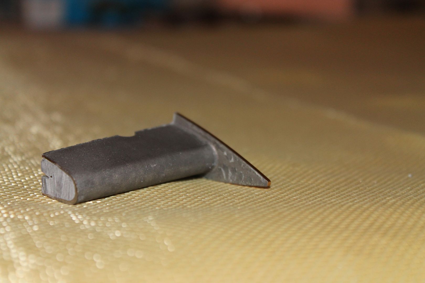
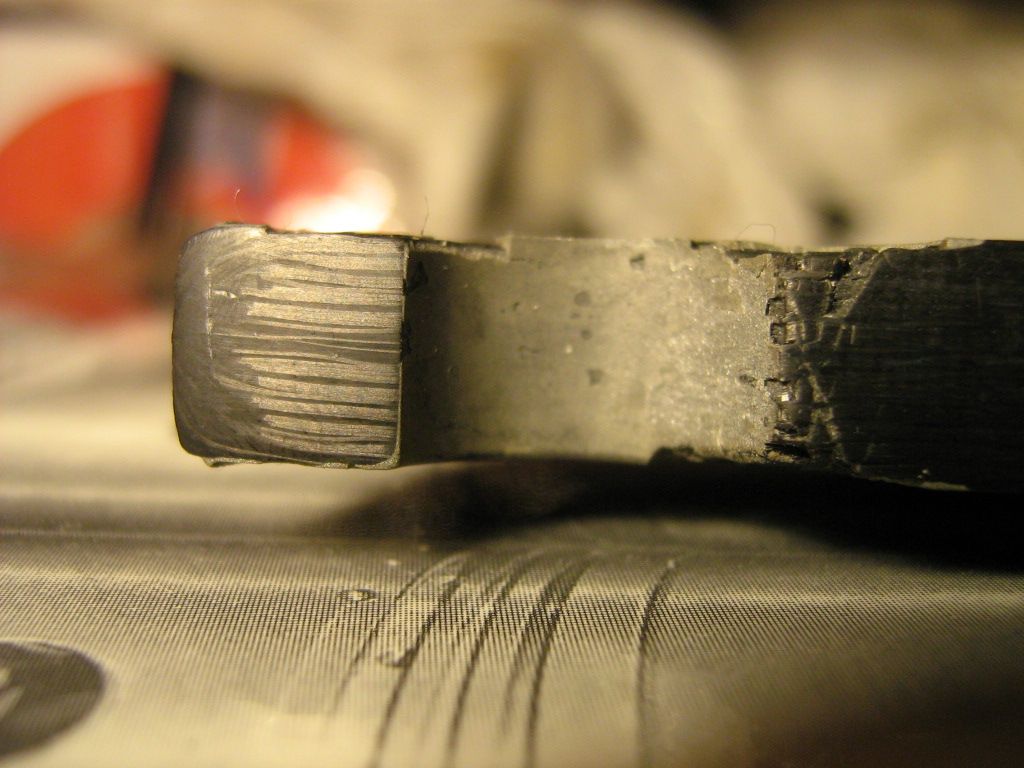
The opposite end of pushrod featured a basic two piece titanium washer and ferrule arrangement bonded into a drilled hole, they have been removed, and are not pictured.

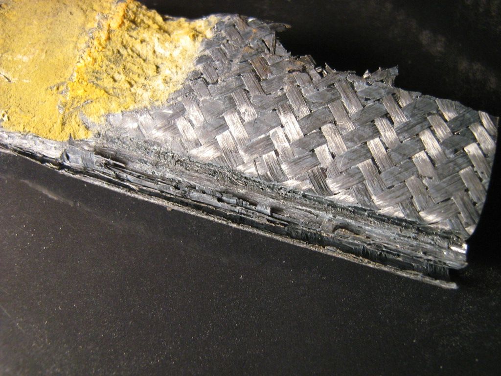
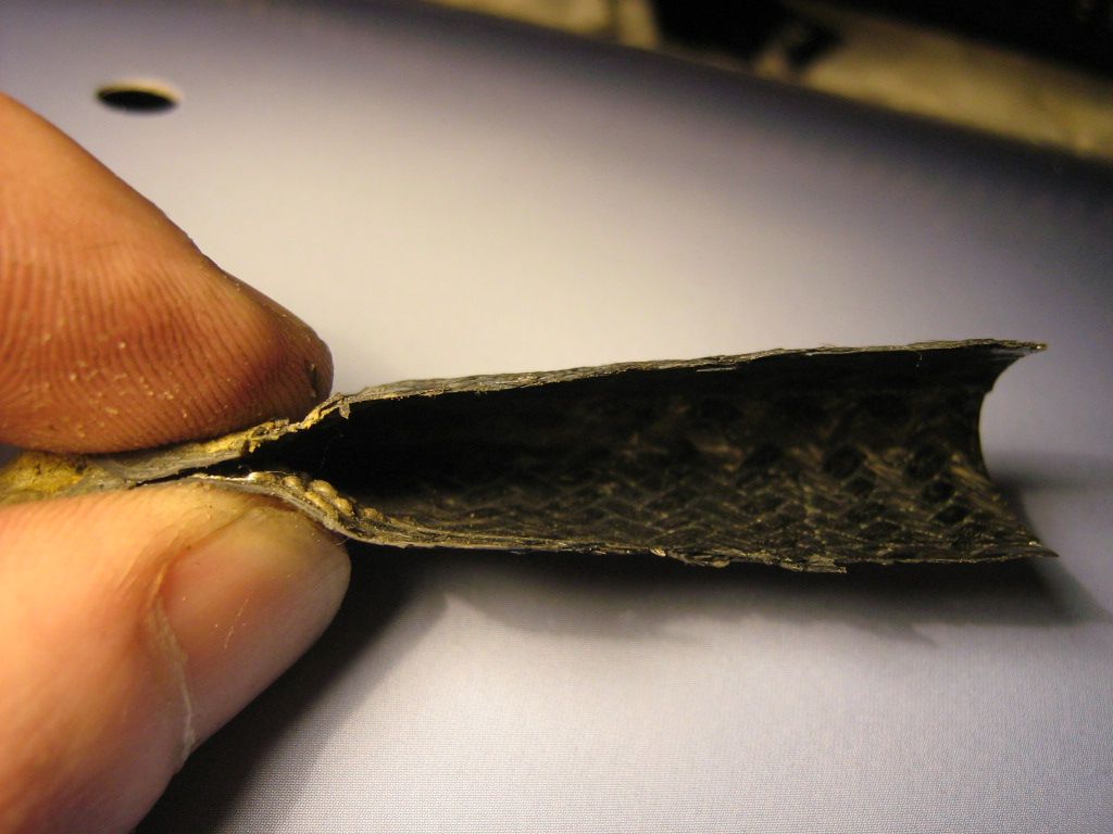
The part is made up from many layers consisting of unidirectional carbon fibre and
twill weave.
Normally, four to seven layers of unidirectional are used, followed by a layer of twill to keep them in place, this is repeated however many times necessary.
If you look very close at the cross-section pictures, you can see that the top and bottom halves are bridged together with a narrow build up of splicing layers.
Since this is pre-preg, all the layers can be built together using a type of mandrel. Since I wasn't present when this was constructed I cannot say for sure how it was constructed. But I can take a guess having been in factories that make similar parts.
A steel male mandrel tool could have been used to build the layers up on. Once built, the mandrel would have been slid out and a tube style bladder inserted.
The assembly would then be placed into a female tool having top and bottom sections to allow part removal.
They are brought up to temperature and the bladder inflated.
Once cured, either with a clave, or heated tools the tools can be opened, and the parted removed. These tools often feature small 'gates' along the part line. These gates all enter side runners in the tool. Depending on setup, the operator may attach a vacuum line to this main runner to help evacuate excess resin. Sometimes, no vacuum line is used and the resin just flows out of its own accord.

Other times, a top and bottom section are made, and both halves bonded together to form the profile.
A foam core is also used sometimes. The layers are built up around this foam mandrel as with the steel mandrel. The assembly is then placed inside the female tool and the halves closed. Because of the slightly oversize foam inside, the layers have to compress in order for tool to close fully.
Pending on where you have the foam left oversize, you can compress more areas of the part than others once the tools close. This way, you can concentrate on areas where the most loads are at the planning stage.

The foam can also be washed out with a solvent once the part is cured, making it even lighter.

There are lots of ways as you can see. Some more suited to wetlay, and others benefiting from pre-preg methods where the operator can take their time laying up various sections around a mandrel, or into a tool with very little mess, or weave disruption.
Trimming is also very easy with pre-preg, and a part can even be built in a modular fashion if you like, where several sections of the part can be laid up in different jigs, and then all brought together in the final tool for the final cure.

This is one of the main differences between wet lay, and pre-preg, it gives the designer greater scope in terms of constructing the part prior to curing. This is not as easy with wet lay, as it can turn into a big mess pretty quick if its a complex part. You can also lose your weave structure very fast the more you work wet lay. This is not the case as much with pre-preg since it is like applying thick masking tape and it tends to stay where its put when warmed and worked into place.

Onto the pictures.

They are pretty much self explanatory. Ill talk a little about the last few macro shots of the ti insert, and its surroundings.

Image

Image

Image

Image

Image

Image

Image

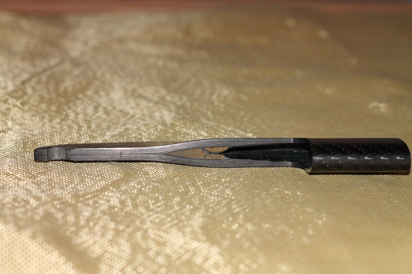
I polished up the inserts cross-section to make it all easier see,

Image

Image

Image

Interestingly enough, the insert fell out of its bonded position once the mechanical fixing was removed. No trace of bonding was present on the ti, it was completely smooth.

Image

Image

Image

Here you can see the grit/media blasted finish of the ti insert.

Image

Next, onto the macro shots of both the insert, and of the layers.

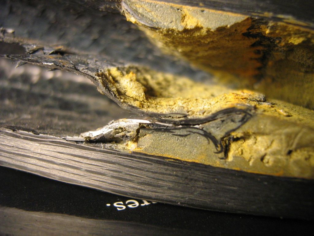
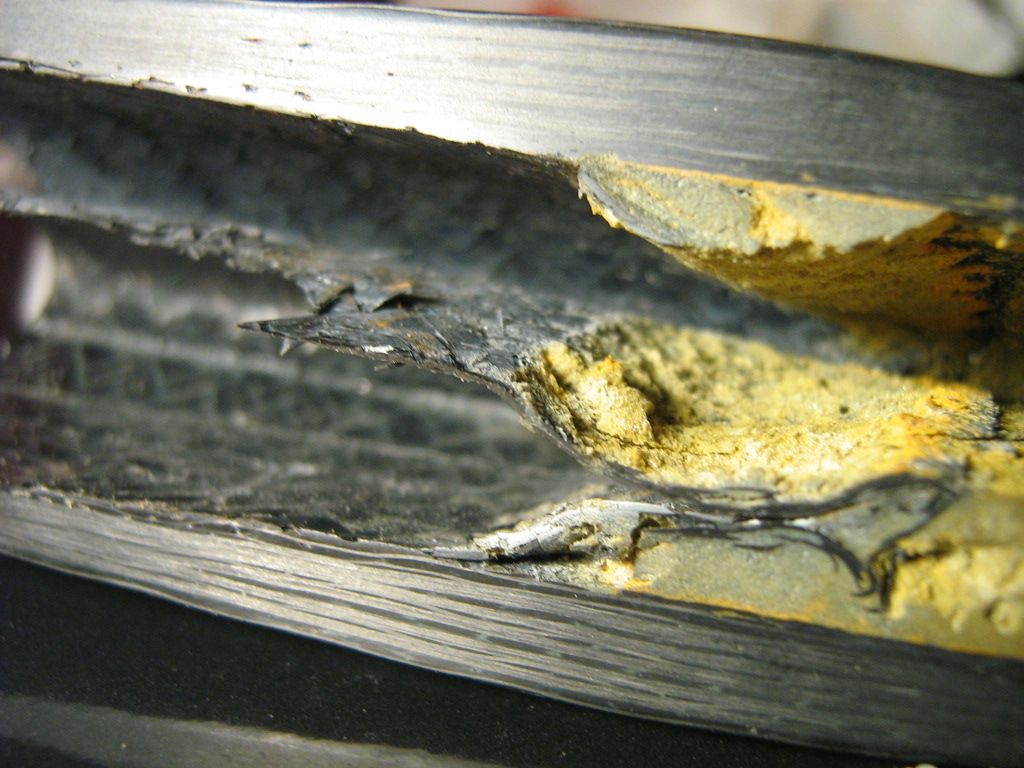
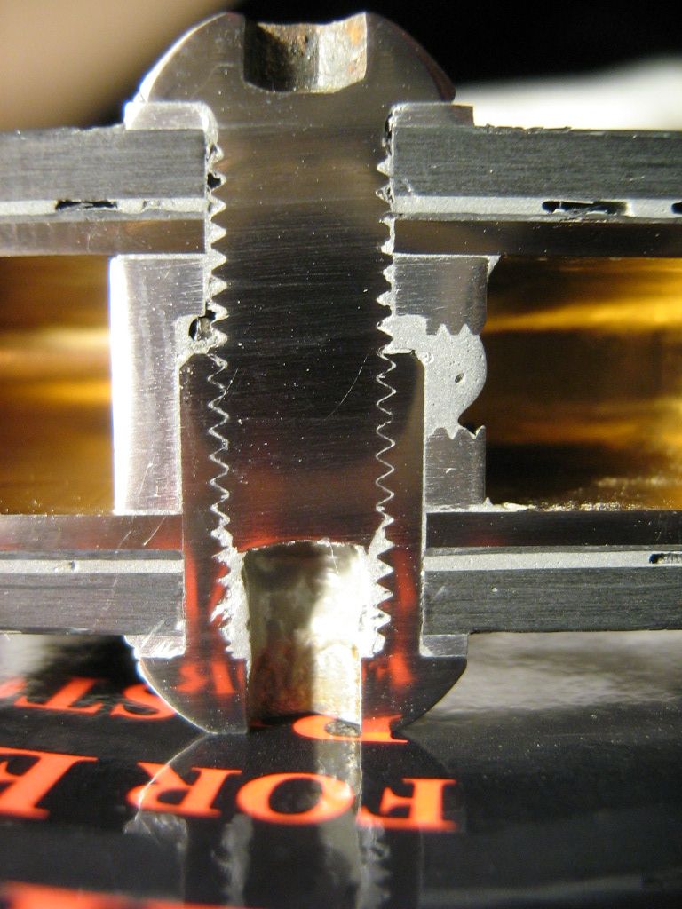
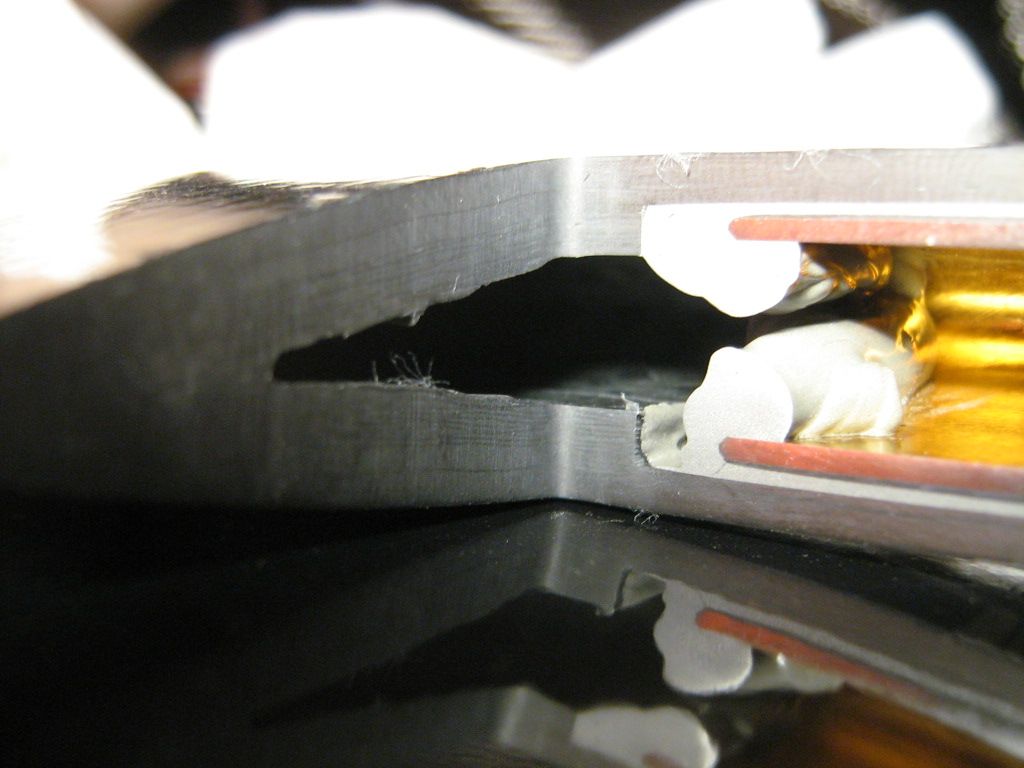
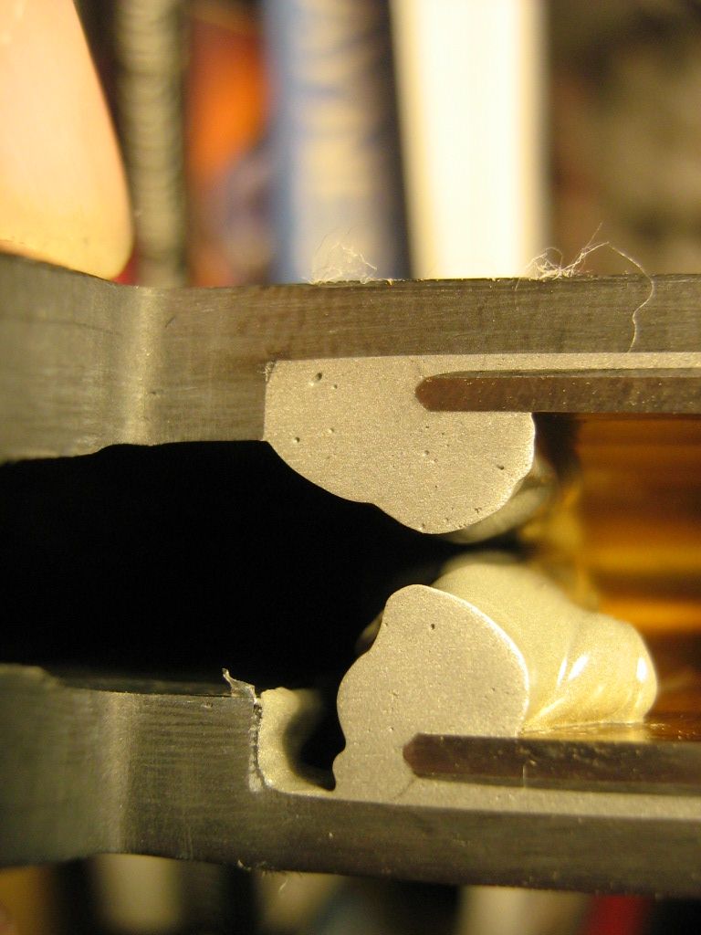
An important shot below,
Theres a lot going on here, so Ill mention the main parts.
From the top down,

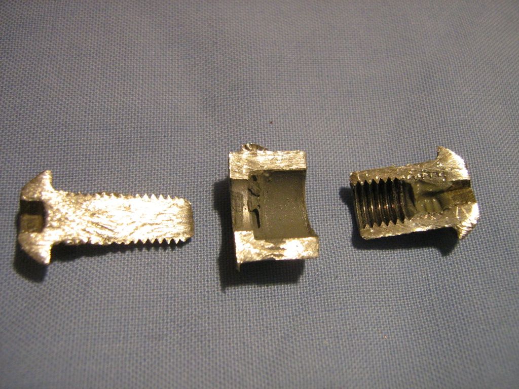
The main bolt ( steel)
Washer (Aluminium)
Wall of pushrod (CF)
Epoxy adhesive
Thin layer of CF applied to ti insert before installing - !this is CF, and not GF!
Insert (Ti)
Spacer (Grit blasted Al)
Hex head insert nut (Steel)

You will also notice a threaded section in the side of the spacer.
From looking at other bonding procedures Im pretty this was used to both position spacer, and also for the pumping in of epoxy adhesive once the bolt was fitted and tightened enough to stop the epoxy flowing out under the bolt and nut heads.
If you look at the top and bottom of spacer where it joins the ti insert, you will notice a thin film of epoxy present, and also some surrounding the spacer itself.
Given that there are no traces of epoxy present like there would be if the insert was slid into place on a bed of epoxy, this further points to the application of epoxy via the side hole in spacer.
The spacer would have been machined a few thou less than the internal size of the ti insert. This slight undersize would allow enough room for epoxy to flow out very slightly at the top and bottom areas of spacer, which it did.
Once filled, the bolt was then tightened fully, completing the bond.
The ti insert also had its coating removed in the spacer bond area. This was carried out with what looks to be a file, or oxide paper.
One last point about the nut insert. You'll notice its not blind, meaning, its got an open hole passing through it. This is done for a few reasons.
It allows excess run-out epoxy adhesive to be removed.
It makes for a lighter nut.
It avoids hydraulic lock, where the epoxy would act as a seal between threads, and excess epoxy builds up in the blind hole, ahead of bolt end.
This has some nasty effects, from not allowing you to insert bolt fully, to swelling the insert.
This last one is the most dangerous, if the insert swells before final bolt torque is reached it can appear to be tight, but the bolt not actually in full tension at all.
The same theory applies to head studs and bolts. If you do not clean blind holes in block of oil or water, you will burst you block on tightening the studs, iron or Aluminium, hydraulics will cause it will pop.

Image

Image

Image

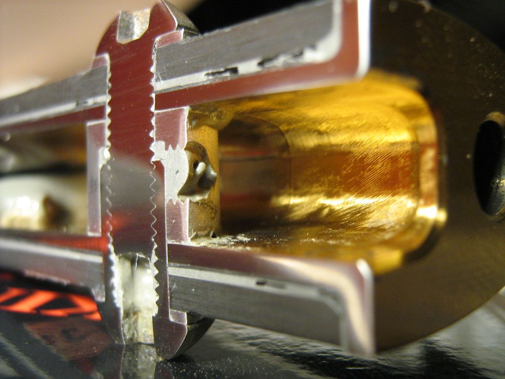
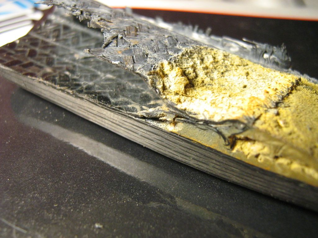
You can also see where the end of the CF profile was machined with an end mill to both clean up the irregular interior, and to also provide a perfect match and bond clearance for the ti insert.

Image

Here, is a small piece cut off, showing the end of the machined pocket section, it extends about 5mm deeper than inserts length.

Image

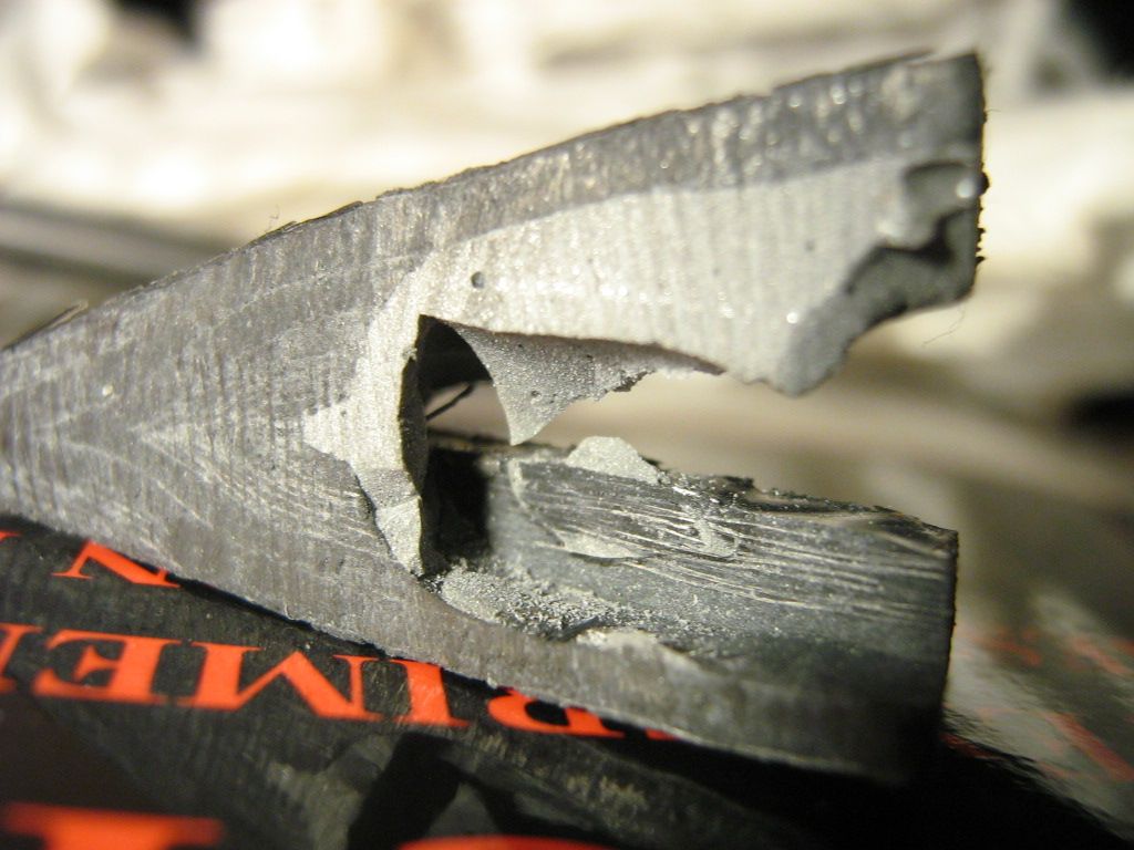
One thing that surprised me a little is the used of an end mill to mill the pocket. You would think a ball nose cutter would have left a smoother transition.
I guess it may not matter considering the force lines, but I still always hate to see sharp 90 degree transitions.

Image

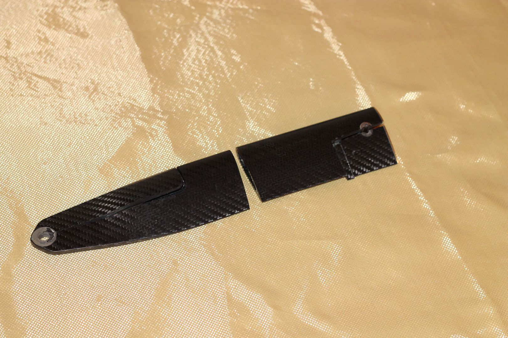
The fixings removed from the non-polished half. Washers omitted,

Image

And now onto a few macro shots of the CF lay-up at different points.

The narrow splicing strips can be seen clearly at both the leading, and trailing edge locations.

Image

Image

Image

Image

Image

Image

Image

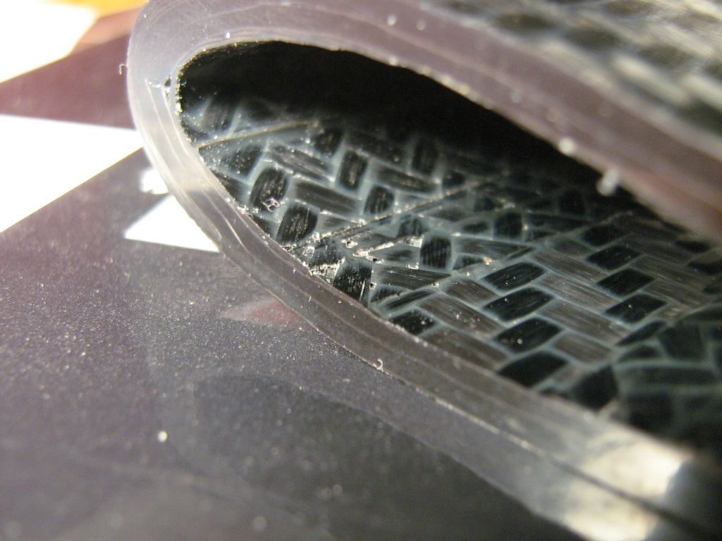
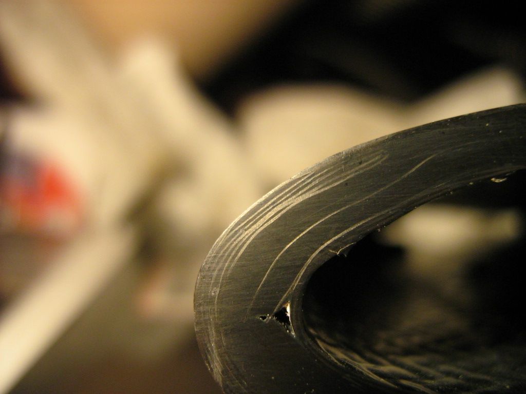
Where both start to converge,

Image

Image

And last, the area surrounding single ti ferrule and washer(removed)

Image

So, there you have it. Another extremely good learning tool for looking at.

What you see here should answer a lot of questions depending on what you want to make some day, it certainly did for me.

A day where you don't learn something new, is a day wasted.

Brian Garvey.
If you think you cant, you wont, If you think you can, you will

User avatar
MIKEY_!
7
Joined: 10 Jul 2011, 03:07

Re: Carbon Fibre pushrod, a closer look.

Post

More great work Brian! Well done! =D> =D> =D>

Just_a_fan
Just_a_fan
591
Joined: 31 Jan 2010, 20:37

Re: Carbon Fibre pushrod, a closer look.

Post

Excellent Brian. Thanks for sharing! =D>

Lots to take in there - I can feel a quiet hour one evening might be necessary...
If you are more fortunate than others, build a larger table not a taller fence.

NonNewtonic
NonNewtonic
0
Joined: 09 Dec 2011, 16:55

Re: Carbon Fibre pushrod, a closer look.

Post

Base the photo by itself it seems like the pushrod is made up of multiple layers of carbon fibre or its just the effect due to the sawing process?or it just made up of carbon fibre envelope filled with epoxy in between? Btw thx for the photos brilliant work you had carry out :) keep it on

Brian.G
Brian.G
334
Joined: 10 Dec 2010, 23:52
Location: Ireland

Re: Carbon Fibre pushrod, a closer look.

Post

NonNewtonic wrote:Base the photo by itself it seems like the pushrod is made up of multiple layers of carbon fibre or its just the effect due to the sawing process?or it just made up of carbon fibre envelope filled with epoxy in between? Btw thx for the photos brilliant work you had carry out :) keep it on
Its made up of many many layers. No envelope filled with epoxy. The twill weave is easier see than the uni, so it appears there are just a few layers with black stuff in between. The black stuff is more layers, uni directional CF.

Brian,
If you think you cant, you wont, If you think you can, you will

User avatar
flynfrog
Moderator
Joined: 23 Mar 2006, 22:31

Re: Carbon Fibre pushrod, a closer look.

Post

nice work. Can you tell what caused the massive wrinkle on the inside of the foam? Was this piece used in a race or was it a reject. I would think that with the hardware installed that is was a good part.

flyboy2160
flyboy2160
84
Joined: 25 Apr 2011, 17:05

Re: Carbon Fibre pushrod, a closer look.

Post

flynfrog wrote:nice work. Can you tell what caused the massive wrinkle on the inside of the foam? Was this piece used in a race or was it a reject. I would think that with the hardware installed that is was a good part.
the orange adhesive at the 'trailing edge' of the internal cavity looks like expanding foam. it probably pushed the innermost woven ply away from the rest of the laminate in the area where there wasn't an internal mandrel or bladder.

there are many voids in both the laminate and the adhesive layers. this is one of the reasons composites have higher safety factors than metals.

also note the very labor intensive 'wrap around' plies where the main laminates come together at the 'trailing edge.'

User avatar
flynfrog
Moderator
Joined: 23 Mar 2006, 22:31

Re: Carbon Fibre pushrod, a closer look.

Post

do you are thinking they injected the foam when the part was uncured and they had that bad of a layup on the bladder or mandrel? We have used heat foaming stuff in the past at core seams. Just seems to be an odd way to build that part what purpose is the foam serving id doesn't appear to have much shear strength to use it as a core.

I think you mean composites are built to higher FOS no that they have a higher one.

engineer_roy
engineer_roy
0
Joined: 02 Nov 2011, 22:13

Re: Carbon Fibre pushrod, a closer look.

Post

What a superb piece of analysis, some really useful original work here.
Last edited by engineer_roy on 07 Jan 2012, 17:47, edited 2 times in total.
Sir Henry Royce, in typically modest fashion, stated his profession as simply ... "Quidvis recte factum quamvis humile praeclarum"

User avatar
humble sabot
27
Joined: 17 Feb 2007, 10:33

Re: Carbon Fibre pushrod, a closer look.

Post

You're right it does look like an expanding foam. Strangely it does look more like it's a liquid foam that got in the wrong place. That and the ease with which the insert came out, suggest to me that this may have been or should have been a reject?

Why do you think the light pits are splicing? Seems to me more likely the polyester that keeps the uni fibers in alignment.

The innermost ply looks to show like wet layup, which surprises me. Or is this a symptom of whatever happened with the foam core; ending up with bad pressure distribution?
the four immutable forces:
static balance
dynamic balance
static imbalance
dynamic imbalance

Brian.G
Brian.G
334
Joined: 10 Dec 2010, 23:52
Location: Ireland

Re: Carbon Fibre pushrod, a closer look.

Post

humble sabot wrote:You're right it does look like an expanding foam. Strangely it does look more like it's a liquid foam that got in the wrong place. That and the ease with which the insert came out, suggest to me that this may have been or should have been a reject?

Why do you think the light pits are splicing? Seems to me more likely the polyester that keeps the uni fibers in alignment.

The innermost ply looks to show like wet layup, which surprises me. Or is this a symptom of whatever happened with the foam core; ending up with bad pressure distribution?
What makes you think the interior layer is wetlay? Because of the surface finish?
Pre-preg can also give off that look when adjacent to a bladder with no resin draw off methods present.
I dont think the foam is in the wrong place.
It looks like most of the layup was done on a mandrel.
Think of the assembled lay up at this point as a headless fish(innards removed)
Once removed off mandrel, some foam was spilled in to increase bond where they meet, inside the fish at his tail.
A bladder was prepared on another mandrel slightly smaller that the first, a few layers are added to bladder in key bridging areas before the undersized mandrel with bladder(and bridging layers) was inserted into the main layup.(down inside the fish)
If you look close, you can see where the layers that were built on the bladder end, and intersect into the foam. If you look even closer, you will see some of the foam that tails off was pushed back into the main layup intersection point as a result of the bladder being inflated.
The entire assembly, think fish, was then fitted to the two piece female tools before bladder inflation.

Thats how I would do it. Sorry to all the fish lovers, but hopefully it makes it easier understand.
As for foam, I dont know would I call it that, its as hard as body filler.

The assembly was certainly bolted into something at some point, and did show some signs of brake dust in certain crevices-but who knows.

Brian,
If you think you cant, you wont, If you think you can, you will

Brian.G
Brian.G
334
Joined: 10 Dec 2010, 23:52
Location: Ireland

Re: Carbon Fibre pushrod, a closer look.

Post

Further dissection of the tail section to expose the inner surface layer which I feel was laid up onto the bladder assembly as described above.

This is the piece in question,

Image

Splitting it apart,

Image

The inner shell remains intact thankfully,

Image

Opening further,

Image

Image

Image

And, breaking off one half for further inspection,

Image

Off,

Image

Image

I was able to remove the inner section almost intact,

Image

Image

The end where I talked about in the previous post, I now believe that the layers were indeed pinched together to close while still on bladder and before bladder assembly was inserted into main layup.

Image

This also makes full sense of why the added 'foam' dispersed as it did in the finished part cross-section due to the inflation action of bladder.

What do we think?

Brian,
If you think you cant, you wont, If you think you can, you will

User avatar
humble sabot
27
Joined: 17 Feb 2007, 10:33

Re: Carbon Fibre pushrod, a closer look.

Post

I see what you were saying before. It does make sense now. Since there had to be some sort of bladder on the inside and the split between the two halves had to be well pressurized from the inside, and the bladder would not have been able to accommodate that, they used a sort of inside out sock as a pedestal for the foam to expand into the tiny space.
the four immutable forces:
static balance
dynamic balance
static imbalance
dynamic imbalance

Brian.G
Brian.G
334
Joined: 10 Dec 2010, 23:52
Location: Ireland

Re: Carbon Fibre pushrod, a closer look.

Post

humble sabot wrote:I see what you were saying before. It does make sense now. Since there had to be some sort of bladder on the inside and the split between the two halves had to be well pressurized from the inside, and the bladder would not have been able to accommodate that, they used a sort of inside out sock as a pedestal for the foam to expand into the tiny space.
Yup, socks and fish is all you need!

Brian,
If you think you cant, you wont, If you think you can, you will

User avatar
flynfrog
Moderator
Joined: 23 Mar 2006, 22:31

Re: Carbon Fibre pushrod, a closer look.

Post

that sorta makes sense not the way I would build that part I guess.