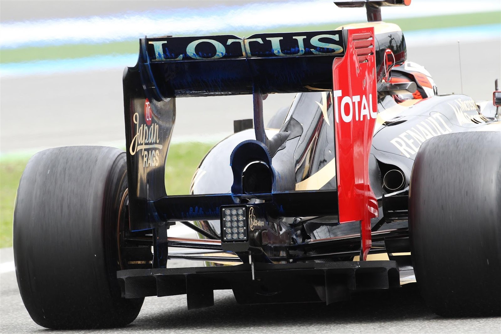
FloViz Interpretation

Here are our CFD links and discussions about aerodynamics, suspension, driver safety and tyres. Please stick to F1 on this forum.
hardingfv32
hardingfv32
32
Joined: 03 Apr 2011, 19:42

FloViz Interpretation

Post

What exactly is the FloViz indicating in the center of the bottom of the main element (wedge shape)?

1) Why does there seem to be a lack of flow in this area? Is that a sign of stagnation?

2) Note the flow around the the blade in the center of the 'wedge zone', why do they turn away from the normal axis of the on coming flow?

3) If this pattern is related to some type of F-duct system, why isn't there some flow lines similar to the rest of the wing entering the 'wedge zone' when the F-duct is not functioning (slow speeds)?

Brian

Image[/quote]

stez90
stez90
8
Joined: 10 Jul 2012, 23:31

Re: FloViz Interpretation

Post

that V-shape is the area affected by turbolence/wakes from the vertical blade (and generally by wing mounts in other racing series).. It decreases the efficency of the wing and that's why LMP cars switched to "swan neck" rear wings.

About "swan neck" VS "conventional" mounts and relative flows check this article on Racecar Engineering for some cfd images and data (expecially page 79): link

User avatar
mep
29
Joined: 11 Oct 2003, 15:48
Location: Germany

Re: FloViz Interpretation

Post

I thought the same but to be honest they would not place it there if it causes that effect.

superdread
superdread
16
Joined: 25 Jul 2012, 22:04

Re: FloViz Interpretation

Post

mep wrote:I thought the same but to be honest they would not place it there if it causes that effect.
Also, effectively stalling ~30cm of the wing seems rather a lot for such a smooth transition between the narrow pylon and the wing (LMP was a lot more crude in that respect).

User avatar
flynfrog
Moderator
Joined: 23 Mar 2006, 22:31

Re: FloViz Interpretation

Post

mep wrote:I thought the same but to be honest they would not place it there if it causes that effect.
the pictures don't lie. That is a text book example of airflow disruption over a wing. Stez is right

hardingfv32
hardingfv32
32
Joined: 03 Apr 2011, 19:42

Re: FloViz Interpretation

Post

superdread wrote:...for such a smooth transition between the narrow pylon and the wing (LMP was a lot more crude in that respect).
I would say the Lotus system would be crude compared to the LMP unit. No reason the LMP unit would not be the correct foil shape for the application, where we think there are slots in the Lotus system.

Brian

superdread
superdread
16
Joined: 25 Jul 2012, 22:04

Re: FloViz Interpretation

Post

flynfrog wrote:
mep wrote:I thought the same but to be honest they would not place it there if it causes that effect.
the pictures don't lie. That is a text book example of airflow disruption over a wing. Stez is right
With the slight difference that here we have a flow blowing the detachment volume increasing the effectively stalled wing area.

Another question: Wouldn't the ridge along the middle mitigate the normal, unblown, wake effect of the pylon?
hardingfv32 wrote: I would say the Lotus system would be crude compared to the LMP unit. No reason the LMP unit would not be the correct foil shape for the application, where we think there are slots in the Lotus system.
Brian
I meant the mounting to the wing, LMP has variable ones that after all carry a lot of load as well.

hardingfv32
hardingfv32
32
Joined: 03 Apr 2011, 19:42

Re: FloViz Interpretation

Post

stez90 wrote:that V-shape is the area affected by turbolence/wakes from the vertical blade (and generally by wing mounts in other racing series).. It decreases the efficency of the wing and that's why LMP cars switched to "swan neck" rear wings.
You are absolutely right about the cause of the V shape.

What would be the explanation for such a flow pattern where the strut comes in contact with the bottom of the wing? In the case of a LMP strut with a perfect foil shape, is there still some turbulence coming of the strut trailing edge?

Can anything be done to improve the flow where the strut comes into contact with the bottom of the wing? Could that be what the slots do in the lotus strut?

Brian

hardingfv32
hardingfv32
32
Joined: 03 Apr 2011, 19:42

Re: FloViz Interpretation

Post

superdread wrote:With the slight difference that here we have a flow blowing the detachment volume increasing the effectively stalled wing area.
My though is that Lotus might be using a flow to correct this V-shaped zone caused by the strut. You have low downforce (less drag?) when there is no blowing of the strut and regain downforce when allow blowing of the strut.

Brian

gato azul
gato azul
70
Joined: 02 Feb 2012, 14:39

Re: FloViz Interpretation

Post

hardingfv32 wrote:
stez90 wrote:that V-shape is the area affected by turbolence/wakes from the vertical blade (and generally by wing mounts in other racing series).. It decreases the efficency of the wing and that's why LMP cars switched to "swan neck" rear wings.
You are absolutely right about the cause of the V shape.
maybe he is maybe not - there are not many "absolutes" in life (he (stez90) does made some good and partly valid points, but perhaps it is not the full story)

any thoughts ?
Image

why not such a pronounced V-shape here then?
Image

no center strut (support) or duct here, but still a V-shaped section starts to form (much smaller as on Lotus) why would that be?
Image

User avatar
flynfrog
Moderator
Joined: 23 Mar 2006, 22:31

Re: FloViz Interpretation

Post

gato azul wrote:Snip
different air speeds could explain the different Vees. You can see a small support in the STR wing causing the stalled area.

hardingfv32
hardingfv32
32
Joined: 03 Apr 2011, 19:42

Re: FloViz Interpretation

Post

In the top photo,STR ?, look at the size of the V-section on the second (red) element formed around the vertical fence. Why put the fence there if this is the flow pattern you are going to get? This has to be what they wanted for a flow pattern. What would possible be good about such a pattern?

How does a fence cause such a flow pattern?

Brian

superdread
superdread
16
Joined: 25 Jul 2012, 22:04

Re: FloViz Interpretation

Post

hardingfv32 wrote:In the top photo,STR ?, look at the size of the V-section on the second (red) element formed around the vertical fence. Why put the fence there if this is the flow pattern you are going to get? This has to be what they wanted for a flow pattern. What would possible be good about such a pattern?

How does a fence cause such a flow pattern?

Brian
It's last years McLaren (quirky sidepods). I think the pattern rather depends on the two v-cutouts at the ridges. I think these are to reduce drag, here used on the main element so they only come to full effect with DRS open.

Otherwise the patterns are heavily influenced by the test pattern (speed, drs open, viscosity of the paint (?)...).

bhall
bhall
244
Joined: 28 Feb 2006, 21:26

Re: FloViz Interpretation

Post

hardingfv32 wrote:[...]

Can anything be done to improve the flow where the strut comes into contact with the bottom of the wing? Could that be what the slots do in the lotus strut?

Brian
Do you contend that Lotus affixed a "strut" to the main plane of the rear wing just so they could fix the flow problem caused affixing a "strut" to the main plane of the rear wing with blown slots on the "strut" they just affixed to the main plane of the rear wing?

stez90 is 100% correct in his assertion that the shape of the flow pattern is caused by the "strut" affixed to the main plane of the rear wing. However, that's incomplete. While the shape of the flow pattern can be attributed to the "strut," the size of the flow pattern is the result of the air that's discharged from the slots in the "strut," which means the "strut" is actually a duct.

rjsa
rjsa
51
Joined: 02 Mar 2007, 03:01

Re: FloViz Interpretation

Post

Ok, Now looking back at it, that thing coming out of the engine fairing is some kind of tubing, and that's activelly stalling that wing.