Nose idea

Here are our CFD links and discussions about aerodynamics, suspension, driver safety and tyres. Please stick to F1 on this forum.
trinidefender
trinidefender
317
Joined: 19 Apr 2013, 20:37

Nose idea

Post

Ok I have come up with an idea for a nose. It is similar to a lotus twin tusk design but the tusks can be made thinner therefore allowing more airflow through them. To do this there is a small wing element set up just above the back of the neutral zone on the front wing. This element can both add to help with the square area rule which allows the tusks to be smaller, also it can be made to add strength to the tusks. This allows that neutral centre section of the front wing to create downforce. Doing this, they can reduce the size of the front wing inner sections so that more flow can pass there instead of the center of the car.

I think I have kept the design legal by making sure that the lower wing section does not overlap with other parts of the nose so therefore even if a line is drawn down through the nose at any point it is still one section.

I drew a few mock pictures free hand while at work, hopefully you guys/girls can follow my intentions. The hatched area is the front wing section on the nose that works with the neutral section. I will try to draw/design better pictures.

Image
Image
Image

PhillipM
PhillipM
385
Joined: 16 May 2011, 15:18
Location: Over the road from Boothy...

Re: Nose idea

Post

Your wing will probably block more air than the thinner tusks would gain, no?

User avatar
turbof1
Moderator
Joined: 19 Jul 2012, 21:36
Location: MountDoom CFD Matrix

Re: Nose idea

Post

I have a feeling this isn't legal; lotus needed to have one tusk 51 cm shorter due the cross section rule. Your nose tips will fall foul for that. It's fixable though; you'd need to extend the plate to the nose tips.

I see you want to create front downforce with it, but it'll do more harm then good. First of all air on the high pressure side will be upwashed overneath the car and will be lost, reducing alr volume underneath the floor. Air on the low pressure side will get upwashed to the underside of the tub, inducing lift. This will nullify the downforce you created with the aerofoil shape.

My advice on that? Either turn it into a neutral shape, or turn the aerofoil upside down. Yes that way it creates lift on the aerofoil itself, but will also reduce underneath the tub, and will increase air volume underneath the floor. I'd personally go for a neutral shape as this will be the safest way while still creating downforce ( aero 101: 2 stacked neutral aerofoils still create downforce).
#AeroFrodo

beelsebob
beelsebob
85
Joined: 23 Mar 2011, 15:49
Location: Cupertino, California

Re: Nose idea

Post

turbof1 wrote:I have a feeling this isn't legal; lotus needed to have one tusk 51 cm shorter due the cross section rule. Your nose tips will fall foul for that. It's fixable though; you'd need to extend the plate to the nose tips.
50mm, not cm. And his solution certainly does have a single cross section 50mm behind the tip of the nose - because the wing joins the two tusks.
I see you want to create front downforce with it, but it'll do more harm then good. First of all air on the high pressure side will be upwashed overneath the car and will be lost, reducing alr volume underneath the floor. Air on the low pressure side will get upwashed to the underside of the tub, inducing lift. This will nullify the downforce you created with the aerofoil shape.
Agreed, it's a legal solution, but not a good one. If you made the shape under there neutral it would effectively become a mercedes nose, but upside down. I'm sure the Merc engineers would have looked at that, and found that it turns out not to work well.

trinidefender
trinidefender
317
Joined: 19 Apr 2013, 20:37

Re: Nose idea

Post

Actually almost by accident I thought of something else. The lower pressure below the wing between the tusks can help draw in air from the side of the lower portion of the sidepods, thereby pulling air to the centreline of the car underneath the nose.

I too, thought that the centre section might make the body of the nose create some lift but if you think back a few years before the centre section of the front wing had to be neutral, all the cars used a downforce producing centre section of the front wing.

thepowerofnone
thepowerofnone
23
Joined: 24 Apr 2013, 17:21

Re: Nose idea

Post

Seems to get the worst of both worlds to me: it both requires a low nose design to ensure the centre of the cross-section is sufficiently low, and it blocks the airflow underneath the car. As mentioned, you could turn the aerofoil upside down (so that it produces lift), but thats only worth it if it can suck in a sufficiently large volume of air that otherwise would not be worked by the car, which in that position is unlikely. It also requires that you then force that air back up at the rear of the car sufficiently, otherwise the net affect of pulling the air down then pushing it back up will be detrimental lift, as well as additional weight.

If you ask me tusks are not a good way to go: sure, they allow you lots of airflow under the car, but they also do not allow you to work that flow into the places you want it to go, and they don't do an awful lot to ensure that air actually makes it under the car rather than spilling around the side pods or similar. Aerodynamically the new Mercedes short nose is the best solution, it allows them to keep it so high.

beelsebob
beelsebob
85
Joined: 23 Mar 2011, 15:49
Location: Cupertino, California

Re: Nose idea

Post

thepowerofnone wrote:Seems to get the worst of both worlds to me: it both requires a low nose design to ensure the centre of the cross-section is sufficiently low, and it blocks the airflow underneath the car. As mentioned, you could turn the aerofoil upside down (so that it produces lift), but thats only worth it if it can suck in a sufficiently large volume of air that otherwise would not be worked by the car, which in that position is unlikely. It also requires that you then force that air back up at the rear of the car sufficiently, otherwise the net affect of pulling the air down then pushing it back up will be detrimental lift, as well as additional weight.
Huh? Why does it need a low nose design? This allows you to get your nose enormously high, because the wing under the tusks lowers the cross section substantially. I agree about it blocking airflow though.

trinidefender
trinidefender
317
Joined: 19 Apr 2013, 20:37

Re: Nose idea

Post

You guys are forgetting that that by this creating downforce in the front you can make the inner sections of the front wing smaller allowing more airflow in those regions inside the front wheel. Also by doing this you can effectively move the major joining point of the tusks to the nose further back and further up allowing more airflow to go there.

3rd. If you move the borrow piece of the sidepanel on the nose up to the level of the bottom of the curve of the mini wing, the low pressure air below the mini wing (I'll dub it as the bridge wing) will suck air in toward the centreline of the car. It can also creat vortices that may be useful if used right.

thepowerofnone
thepowerofnone
23
Joined: 24 Apr 2013, 17:21

Re: Nose idea

Post

beelsebob wrote:
thepowerofnone wrote:Seems to get the worst of both worlds to me: it both requires a low nose design to ensure the centre of the cross-section is sufficiently low, and it blocks the airflow underneath the car. As mentioned, you could turn the aerofoil upside down (so that it produces lift), but thats only worth it if it can suck in a sufficiently large volume of air that otherwise would not be worked by the car, which in that position is unlikely. It also requires that you then force that air back up at the rear of the car sufficiently, otherwise the net affect of pulling the air down then pushing it back up will be detrimental lift, as well as additional weight.
Huh? Why does it need a low nose design? This allows you to get your nose enormously high, because the wing under the tusks lowers the cross section substantially. I agree about it blocking airflow though.
If you used a high nose with this design there is no way that thing would pass an impact test, it will necessitate that you lower the nose significantly to pass them and wipe out many of the "high nose" gains. Two thin sections will not pass it: Lotus can do it because their nose is actually quite thick, but this idea uses much thinner sections. Unless the aerofoil we uses joins up to the "main" nose (by main I mean the part that is reasonably conventional) it will likely fail at the joint between the tusks and the "main" nose - in the case that it does join up, you just have a really horribly inefficient aero geometry and may as well not pursue the design because there will be so much blockage.

bhall
bhall
244
Joined: 28 Feb 2006, 21:26

Re: Nose idea

Post

Back when teams weren't compelled to use a neutral center section, there was quite a bit of work done to minimize the sort of drag this proposed wing would seem to create.

There was the needle nose of the Renault R25, among others, that presented a thinner blockage to the upwash created by the "spoon" portion of the wing. (At least, I think that was the idea.)

Image

The F2008 streamlined the underside of the nose behind the trailing edge of the wing....

Image

...and was eventually fitted with a duct that allowed upwash to simply pass through the nose. (There was a wing mounted within it, too.)


Even with no upwash at all, Red Bull streamlined the underside of the nose and chassis on the RB5 and RB6 to minimize similar drag.

Image

And looking a bit further back, the Chaparrall 2E used the same concept, too. (I think it was the original.)

Image
(If anyone has a picture of the real 2E without the front bodywork, please post it, as I couldn't find a thing other than this model.)

I have no ideas about the efficacy of the proposed wing. I'm just throwin' this stuff out there to be chewed over.

trinidefender
trinidefender
317
Joined: 19 Apr 2013, 20:37

Re: Nose idea

Post

thepowerofnone wrote:
beelsebob wrote:
thepowerofnone wrote:Seems to get the worst of both worlds to me: it both requires a low nose design to ensure the centre of the cross-section is sufficiently low, and it blocks the airflow underneath the car. As mentioned, you could turn the aerofoil upside down (so that it produces lift), but thats only worth it if it can suck in a sufficiently large volume of air that otherwise would not be worked by the car, which in that position is unlikely. It also requires that you then force that air back up at the rear of the car sufficiently, otherwise the net affect of pulling the air down then pushing it back up will be detrimental lift, as well as additional weight.
Huh? Why does it need a low nose design? This allows you to get your nose enormously high, because the wing under the tusks lowers the cross section substantially. I agree about it blocking airflow though.
If you used a high nose with this design there is no way that thing would pass an impact test, it will necessitate that you lower the nose significantly to pass them and wipe out many of the "high nose" gains. Two thin sections will not pass it: Lotus can do it because their nose is actually quite thick, but this idea uses much thinner sections. Unless the aerofoil we uses joins up to the "main" nose (by main I mean the part that is reasonably conventional) it will likely fail at the joint between the tusks and the "main" nose - in the case that it does join up, you just have a really horribly inefficient aero geometry and may as well not pursue the design because there will be so much blockage.
Considering that the bridge wing can be made structural it should be able to pass crash tests. A big reason that the lotus tusks are so thick is not only for strength in head on collisions but for collisions at slight angles to the nose. They are singular, long slender structures so there has to be a lot of carbon to take the stress. With this design the bridge wing connects the two tusks which helps with strength quite a lot. The strength comes from the shape. This is why I think that you would be able to make the tusks much thinner than lotus and still pass the crash tests.

beelsebob
beelsebob
85
Joined: 23 Mar 2011, 15:49
Location: Cupertino, California

Re: Nose idea

Post

Right, of course it could be made to pass a crash test - Mercedes effectively have made a nose exactly like this, but upside down, and theirs passed.

___
___
5
Joined: 09 Feb 2012, 01:51

Re: Nose idea

Post

3.7.1 wrote:Forward of a point lying 450mm ahead of the front wheel centre line and less than 250mm
from the car centre line and less than 125mm above the reference plane, only one single
section may be contained within any longitudinal vertical cross section parallel to the car
centre line.

Furthermore, with the exception of local changes of section where the bodywork defined in
Article 3.7.2 attaches to this section, the profile, incidence and position of this section must
conform to drawing 7.
Drawing 7 defines the neutral section, with its trailing edge 87mm above the reference plane. So first of all your extra wing must lie in its entirety at least 38mm higher than the neutral section trailing edge.
3.7.8 wrote:Only a single section, which must be open, may be contained within any longitudinal vertical
cross section taken parallel to the car centre line forward of a point 150mm ahead of the front
wheel centre line, less than 250mm from the car centre line and more than 125mm above the
reference plane.
And herein lies the main problem - any side view section you cut through the extra wing must join to the rest of the car.

So you have a little bit of legalising to do!

As other people have pointed out, after all this you don't just have to generate front downforce - you can easily get this by increasing the front flap angle, which the drivers rarely have all the way up to the top of the range (for a well balanced car) - it has to create that downforce more efficiently than the flap does.

trinidefender
trinidefender
317
Joined: 19 Apr 2013, 20:37

Re: Nose idea

Post

___ wrote:
3.7.1 wrote:Forward of a point lying 450mm ahead of the front wheel centre line and less than 250mm
from the car centre line and less than 125mm above the reference plane, only one single
section may be contained within any longitudinal vertical cross section parallel to the car
centre line.

Furthermore, with the exception of local changes of section where the bodywork defined in
Article 3.7.2 attaches to this section, the profile, incidence and position of this section must
conform to drawing 7.
Drawing 7 defines the neutral section, with its trailing edge 87mm above the reference plane. So first of all your extra wing must lie in its entirety at least 38mm higher than the neutral section trailing edge.
3.7.8 wrote:Only a single section, which must be open, may be contained within any longitudinal vertical
cross section taken parallel to the car centre line forward of a point 150mm ahead of the front
wheel centre line, less than 250mm from the car centre line and more than 125mm above the
reference plane.
And herein lies the main problem - any side view section you cut through the extra wing must join to the rest of the car.

So you have a little bit of legalising to do!

As other people have pointed out, after all this you don't just have to generate front downforce - you can easily get this by increasing the front flap angle, which the drivers rarely have all the way up to the top of the range (for a well balanced car) - it has to create that downforce more efficiently than the flap does.
The way that rule is defined is looking from the top it has to be one section. Otherwise the mercedes and the lotus nose would fail. The way I have designed it is looking from the top at any point you will always only see one section.

Adding front downforce can be increased by adding front wing angle however this has other implications.
1. As you add flap angle the drag created by said wing goes up more than proportional to the level increased downforce.
2. Wings are designed with a maximum design wing angle, whereby, passed this point the stall will be quite abrupt and over a large surface of the wing.
3. The main point. By increasing the wing angle you are reducing both the mass flow and the quality of said mass flow of air going to the back of the car sacrificing some rear downforce. People always talk about the mass flow going under the nose to the back of the car however nobody talks about the air flowing next to the air underneath the nose. I.e. The air flowing inside of the front wing but not under the nose.

My idea is to use part of the centre section wing to create downforce with the bridge wing in the open centre of the nose. By this creating downforce the inner sections of the front wing can be made smaller/lower angle of attack/combination of the two. This has the knock on effect of the front wing disturbing airflow going under/through the suspension less and allowing more airflow to the rear.

thepowerofnone
thepowerofnone
23
Joined: 24 Apr 2013, 17:21

Re: Nose idea

Post

trinidefender wrote:Considering that the bridge wing can be made structural it should be able to pass crash tests. A big reason that the lotus tusks are so thick is not only for strength in head on collisions but for collisions at slight angles to the nose. They are singular, long slender structures so there has to be a lot of carbon to take the stress. With this design the bridge wing connects the two tusks which helps with strength quite a lot. The strength comes from the shape. This is why I think that you would be able to make the tusks much thinner than lotus and still pass the crash tests.
beelsebob wrote:Right, of course it could be made to pass a crash test - Mercedes effectively have made a nose exactly like this, but upside down, and theirs passed.
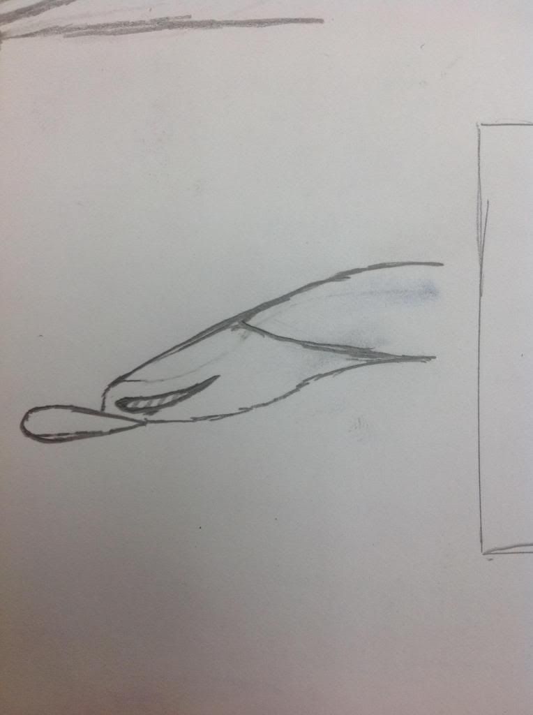
Right, I'll start by referring you to my original comment where I state and fully admit that a Mercedes solution can work, and is in my opinion the optimal solution, so let's all agree on that now. The Mercedes solution is effectively a tusk pair with a panel over the top on one edge, forming a C shaped cross section - whilst it is an open section it has a reasonable stiffness.

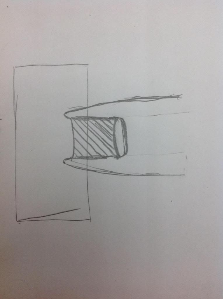
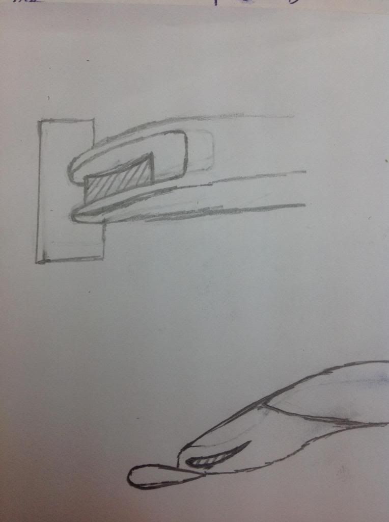
Now, lets return to this problem: the cross section as it is draw goes from an I I cross section, to an H cross section, to an I I cross section, to a box cross section. The reason this design would not pass a structural test is that the I I section is, by its very design intent, very thin on both sides - the design exploits this fact to its advantage, if the design didn't exploit this fact there would be no point implementing it. The H cross section, as trinidefender points out, is very similar to the Mercedes design, and can likely be made to pass a crash test (I am referring to this section ONLY). The problem is that this design then goes back to an I I section, and this is where it differs from the Mercedes solution. As before, this I I section is extremely weak, because as before these sections are very thin which not only limits cross sectional area but also sectional stiffness. Both of the I I sections represent areas of extreme structural weakness which will consume very little energy (relatively) to compress and will also be difficult to design such that they fail in the correct manner, again, due to their thinness. Should the I I section between the H and box sections fail prior to the H section (which it almost certainly will due to the smaller cross sectional area therefore higher stress), the H section will not fail in the correct manner either, because the section behind it has failed, allowing it to distort out out plane rather than disintegrate.

As I state in my subsequent post, the solution to this would be to eliminate the I I section between the H section and the box section, which reduces to the C section design of the Mercedes which I already stated is the design I believe to be optimal. The C and H sections have virtually identical cross sections, although the C section is aerodynamically more beneficial as it allows a greater area below the horizontal component for airflow under the car.

tl;dr I agree the concept can be altered to pass the structural requirements, albeit with some difficulty as illustrated by just how long it took Mercedes to get their short nose design out, however this altered solution reduces to the Mercedes solution, which is not novel and as in my previous post, is likely the best solution.

EDIT: reading this back it comes off quite defensive and damning of your design; this is not the intent. I actually like what your design is trying to do, I just feel that when you have worked it all the way through it reduces to the Mercedes design, which is what I believe to be the optimal design, so very well done.