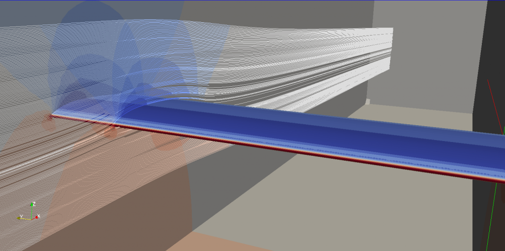
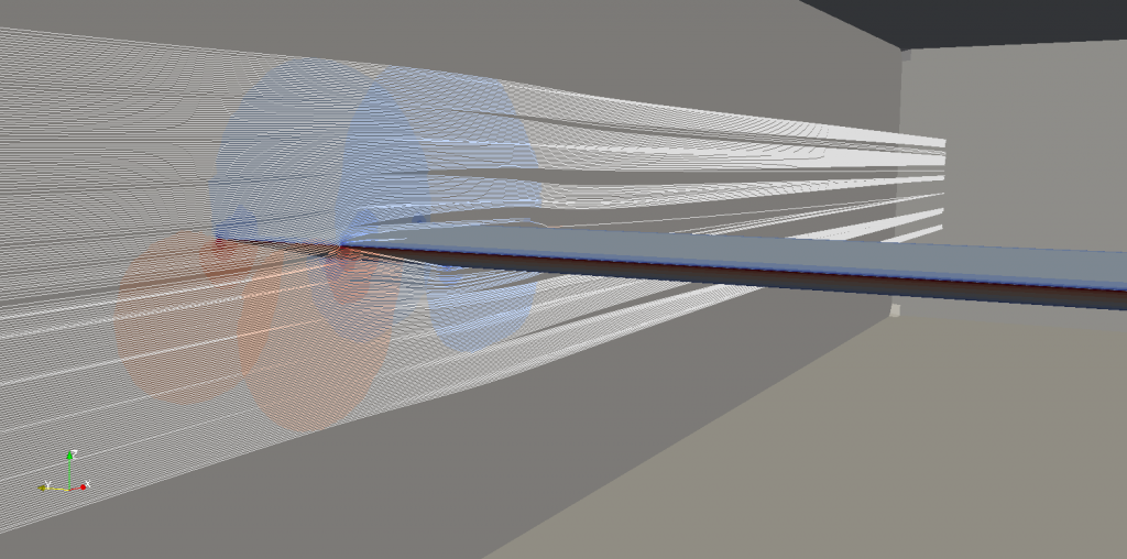
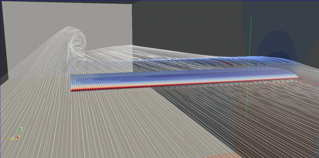
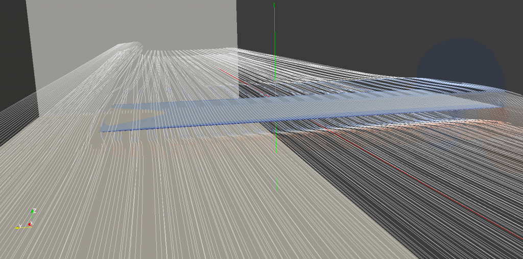
I agree. Winglets are devices that produce an airflow at the end of the horizontal span that results in better lift/drag performance from the wing. And the airfoil profile of the vertical tip of the winglet is designed to produce minimal wake vortex flow. But since the AoA of the tip airfoil is fixed it still can generate tip vortex wake flows under conditions of yaw or pitch.trinidefender wrote: Still want to try to tell me that they are vortex GENERATING types? The winglets reduce the size and strength of a wingtip vortex that is present on a winglet-less wing design. In actuality fact you can say that they are vortex reducing devices.
Regardless, given the size (6-8 ft) and weight ( a couple hundred pounds each) of the winglets used on some commercial aircraft like the 737, they must be very effective at improving main wing lift versus the amount of drag they add.