Formula 1 wings

Here are our CFD links and discussions about aerodynamics, suspension, driver safety and tyres. Please stick to F1 on this forum.
asdf10101
asdf10101
0
Joined: 27 Jul 2009, 15:04

Formula 1 wings

Post

Hi all

i want to ask for help about my FYP.. im doing a CFD study on the differences between 2008 and 2009 regulations.. i wanted to do a simulation using star-cd star ccm and star design.. my target was to used a simplified front and rear wing.. for example for front wing, i will only use 1 airfoil.. and for rear wing i will use multiple airfoil possibly 3..
so basically i will have 2 front wing (1 for 2008 dimension and 1 for 2009 dimension)
same goes to rear wing..
the aim is to find drag coefficient and lift coefficient and also downforce.. but the problem is

1. i dont know whether it is capable to make FYP not based on publish journal
2. i dont know which airfoil to be used (front and rear)
3. i wanted to prove that 2009 regulation increase the overtaking opportunities but how do i know about it? from Cd or Cl?

another thing i want to ask is.. does the height of a wing affect the downforce? i mean same airfoil size but from different height.
1. let say 1 meter
2. 0.2 meter
and the width does it play a role in downforce?

i think my title will not be successful.. please help me :idea:

Scotracer
Scotracer
3
Joined: 22 Apr 2008, 17:09
Location: Edinburgh, Scotland, UK

Re: Formula 1 wings

Post

To show an improvement in over-taking you must first use two cars in tandem (really the only way to do that is wind-tunnel) to find out what changes will improve the following car. Looking at Cl or Cd alone wont tell you anything.

One major aero component you are missing is the diffuser. If you leave that out you really are not going to have representative results as it contributes as much downforce as the front wing and has a coupling effect on the rear wing. Also, during the OWG's testing, they found that it was the diffuser that suffered most from following a car.

Ground effect is fundamental to a wing's performance so yes, it's height does affect it (it doesn't affect the rear wing as that component's underside is parallel to the bodywork) vastly. The lower the front wing, the more downforce it will produce.

Your 2nd point asks which aerofoil...well, you're going to have to run more than one as the rear-wings are twin element and the front wing can be multiple. Just look at the NACA wings that look closest to a real F1 wing and adjust them appropriately. Each element is fundamentally different too.
Powertrain Cooling Engineer

Jersey Tom
Jersey Tom
166
Joined: 29 May 2006, 20:49
Location: Huntersville, NC

Re: Formula 1 wings

Post

What is a FYP?
Grip is a four letter word. All opinions are my own and not those of current or previous employers.

mikhak
mikhak
11
Joined: 10 Jul 2006, 02:25
Location: Stockholm

Re: Formula 1 wings

Post

Jersey Tom wrote:What is a FYP?
I believe it's Final Year Project.

You could do one simulation of the front wing in clean air and then put the rear wing at some distance ahead of the front wing and look at the change in Cl for the front wing. Do this for both 2008 and 2009 wings and this could give an indication of which regulations have the biggest reduction in downforce for the following car.

I've not used star-cd star ccm or star design and i don't know you level of expertise in flow simulation but it's not a simple job to mesh multi-element airfoils and the simulation may be very big with both front and rear wings to have grid independence. But you could always just do have the wings which would reduce it abit. In addition to that the above is a very simplified example of what is going on, excluding the diffuser, flow over the car, tyres etc. But you can always propose it and get somebody to see if it's FYP worthy.

I mentioned this before in a thread here........that Ferrari did a computer simulation to see the effect of following in another car's wake for the FIA. They ran a simulation for half a car (eg. the left half) and saved the velocity field behind this car, ie. the wake, and then introduced this as the boundary condition at the beginning of the domain. Even this didn't give a great correalation with the experiments they performed on track.


keep us updated on the progress if you do anyway.

asdf10101
asdf10101
0
Joined: 27 Jul 2009, 15:04

Re: Formula 1 wings

Post

yes FYP = final year project

from my understanding.. what u mean is.. i model all 4 wings (2 front and 2 rear)

1. after the inlet.. i place the rear 2008 and then front 2008.. and find the downforce..
2. same but replace with rear 2009 and front 2009 and find the downforce..

to get a graph,,, i can put a distance from the rear and front let say... 3 meter, 2.5, 2.0, 1.5, 1.0 and 0.5... but without the effect of diffuser of course..

about the diffuser, i think it is same as the simplified wing because to draw a real wing and diffuser, it requires skill.. i only learn 1 semester in solidwork, 1 semester in CATIA and for the star-cd im only taking it this semester.. but for this FYP,, this semester is only litereature review.. next sem will be the modelling and simulation.. so thats why im asking is it possible to make this title.. or there is any suggestion from any of you who are expert in CFD.. please help me [-o<

my supervisor told me that a project which is simplified at first can be continue by another student as their FYP later.. so it will become better and better.. im saying this as i think the formula 1 team are using more than 1 person to run the simulation + modelling and plus they are using super duper computer.. so i think simplifying is ok.. i need help to make this title interesting because after a while i see it cant be done.. my supervisor doesnt really know about f1.. i think he allowed me to continue on this FYP is only because he can see that im interested..

do i really need to draw the diffuser,,, i think i can draw it but maybe simpliflied and where to get the dimension? about modelling.. i once draw a formula 1 car in solidwork.. but not accodring to the dimension.. just as hobby after i learn it.. but it looks not nice but ok

mikhak
mikhak
11
Joined: 10 Jul 2006, 02:25
Location: Stockholm

Re: Formula 1 wings

Post

yeah that's the idea more or less. except i would look at change in downforce between front wing alone and front wing + rear wing in clean air. so......

1. 2008 front wing on it's own.. and find the downforce..
2. 2009 front wing on it's own.. and find the downforce..
and then as you describe:
asdf10101 wrote: 3. after the inlet.. i place the rear 2008 and then front 2008.. and find the downforce..
4. same but replace with rear 2009 and front 2009 and find the downforce..
and then vary the distance between the front and rear wings, would give an interesting graph. I don't know how accurate the results would be now.
The diffuser is a major part of the rear downforce and massively effects the flow from the rear of the car and therefore the front wing of the following car. To do the steps above is not simple so may be just too much work to include the diffuser.
If it can be a continuation project then the above steps may be good ground work for future projects.....

asdf10101
asdf10101
0
Joined: 27 Jul 2009, 15:04

Re: Formula 1 wings

Post

thank you very much.. at least i can see where im heading now..

i have read a journal on CFD study of section characteristics of Formula Mazda race car wings
W. Kieffera, S. Moujaesb,, N. Armbyab

and it mention about angle of attack and ground effect.. correct me if im wrong... i think that i dont have to add the ground effect (0.05,0.1,0.15 meter from ground) because i will use a dimensioned front wing and it is fixed at x.x meter from ground.. and for the angle of attack.. should i include it for 0, 4, 8 degree? or just pick 1..

let say if i have a rear wing.. for monza type which is almost flat ( - ).. and for spain.. maybe half of ( U )... the radius difference between them is called angle of attack or what is it.. since f1 car using difference setup for different track.. i plan to choose same angle for front and also rear wing which mean i dont have multiple angle of attack ?

sorry for the broken english

xpensive
xpensive
214
Joined: 22 Nov 2008, 18:06
Location: Somewhere in Scandinavia

Re: Formula 1 wings

Post

I wonder what a "typical" Cv-value for an F1 rear-wing is, close to 1 I would guess?
"I spent most of my money on wine and women...I wasted the rest"

asdf10101
asdf10101
0
Joined: 27 Jul 2009, 15:04

Re: Formula 1 wings

Post

Cv = drag force?

i have read somewhere that for racing car.. the lower the better (< 0.4) but formula 1 it is between 0.7 to 1


edit

For example, typical examples of drag coefficients for typical automobiles are between 0.3 and 0.5. In particular,
1. 0.36 : Honda Civic (2001)
2. 0.31 : Honda Civic (2006)
3. 0.29 : Honda Accord Hybrid (2005)
4. 0.35 : Toyota MR2 (1998)
5. 0.34 : Ferrari F40 (1987)
6. 0.57 : Hummer H2 (2003)
7. 0.7-1.1 : Formula 1 car
Typical drag coefficients for some other bodies are:
1. 2.1 : smooth brick
2. 0.9 : bicycle + rider
3. 0.4 : rough sphere (Re =106)
4. 1.0-1.3 : person (upright)
5. 1.0 -1.1 : skier

source
ftp://ftp.colorado.edu/cuboulder/course ... agCoef.pdf

xpensive
xpensive
214
Joined: 22 Nov 2008, 18:06
Location: Somewhere in Scandinavia

Re: Formula 1 wings

Post

Question was if anyone knew the Cv-value for the rear wing itself.
"I spent most of my money on wine and women...I wasted the rest"

kilcoo316
kilcoo316
21
Joined: 09 Mar 2005, 16:45
Location: Kilcoo, Ireland

Re: Formula 1 wings

Post

asdf10101 wrote:Hi all

i want to ask for help about my FYP.. im doing a CFD study on the differences between 2008 and 2009 regulations.. i wanted to do a simulation using star-cd star ccm and star design.. my target was to used a simplified front and rear wing.. for example for front wing, i will only use 1 airfoil.. and for rear wing i will use multiple airfoil possibly 3..
so basically i will have 2 front wing (1 for 2008 dimension and 1 for 2009 dimension)
same goes to rear wing..
the aim is to find drag coefficient and lift coefficient and also downforce.. but the problem is

1. i dont know whether it is capable to make FYP not based on publish journal
2. i dont know which airfoil to be used (front and rear)
3. i wanted to prove that 2009 regulation increase the overtaking opportunities but how do i know about it? from Cd or Cl?

another thing i want to ask is.. does the height of a wing affect the downforce? i mean same airfoil size but from different height.
1. let say 1 meter
2. 0.2 meter
and the width does it play a role in downforce?

i think my title will not be successful.. please help me :idea:

Sorry, I think your going about it in the wrong way, and I think you've made a bad assumption in choosing a single element front wing.


In this instance, I feel you need to diagnose the problem, and then try to quantify it.


So, we know the front wing downforce dropping off in a car's wake was and still is the problem.

Consider the front wing in isolation, make a proper elemented wing - here are a few profiles to get you going:

Image

Image

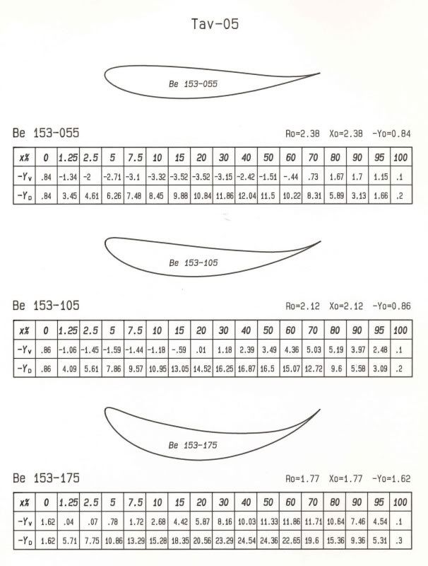
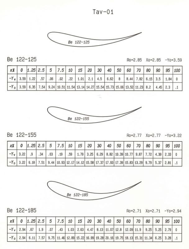
You can build your own basic multi-element wing from this in any CAD package, or probably better, a mesher directly.

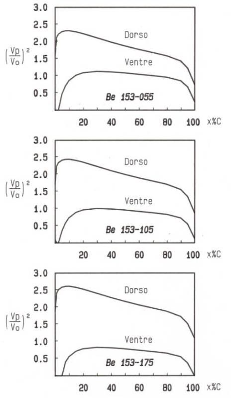
Validate your CFD based on isolated aerofoil performance at 0 degrees angle of attack:

Image

Image


You can then look at the sensitivity of the multi-element wing to both turbulence intensity, and local angle of incidence (different from angle of attack!). I would recommend keeping these as boundary conditions you can explicitly impose, rather than use an upstream diffuser/rear wing combination (although you might want to make one to get an idea of the effects of an upstream diffuser/rear wing on the flow stream.


You need to be careful to avoid your problem growing to unmanageable mesh sizes. So I wouldn't look far beyond an isolated front wing assembly and vary the boundary conditions upstream of it (using set boundaries) to see the effects.

Bite off more than you can chew and you'll make a balls of the whole thing. Keep it simple and compact, then you can properly investigate the area.

asdf10101
asdf10101
0
Joined: 27 Jul 2009, 15:04

Re: Formula 1 wings

Post

hi thanks kilcoo..
so you mean i have to use 2 element of airfoils for the front wing? what ive seen from pictures.. for 2008..
Image
for 2009
Image
the shape are different.. for 2008 they are more like a u in the middle but for the 2009 the shape are almost flat.. i was thinking to use same shape (flat) except that the dimension are according to the year.. but what do you think about it.. should i draw it according to real shape?
i have search tutorial to draw the airfoil but i didnt manage to find.. is there any tutorial you guys have?? im using CATIA P3 V5R17
i only learn basic things in catia during class.. ive also download javafoil but didnt explore it yet

i also want to ask.. for the front wing.. do i need to draw like this
Image
or just this part
Image

sorry for all those questions.. i really really know nothing about this

Scotracer
Scotracer
3
Joined: 22 Apr 2008, 17:09
Location: Edinburgh, Scotland, UK

Re: Formula 1 wings

Post

I have to ask: If you "really know nothing about this" then why are you doing a final-year project on it? FYPs are (from my experience) time restricted and as such you need to know what you're doing to some extent as you'll never get it finished otherwise.

On topic:

The flat section of the 2009 front wing can be found here:

Image


Click for full-size image.

2009 F1 Regs

That should make things a bit easier.

The 2008 front wing central section is the same height above the reference plane as 2009 but much thinner...and the aerofoil is unlimited in that area.
Powertrain Cooling Engineer

asdf10101
asdf10101
0
Joined: 27 Jul 2009, 15:04

Re: Formula 1 wings

Post

yes like i said before.. i went to ask the supervisor about his topics.. and he told me some of the topics and asked me if i have a topic.. i just told him im really interested in f1 and what about the difference in changes made from 2008 and 2009... and he told me to search about it.. ive search and found article but not journal (except cfd on formula mazda).. i can find the major dimension but not the exact dimension from any team as it is restricted and not shared.. i thought it was going to be easy to just do the modelling and run.. at that time i didnt enter the CFD class yet so i have no clue what ill be doing.. it just happen that he allow me to do this topic.. and after i enter the CFD class.. even to find the drag force around a cylinder.. i dint manage to find :(
its not that i cant read the article or journal about CFD.. i just dont really understand it.. im not good in english so by asking in forum i thought it was going to be easy to understand

kilcoo316
kilcoo316
21
Joined: 09 Mar 2005, 16:45
Location: Kilcoo, Ireland

Re: Formula 1 wings

Post

asdf10101 wrote:at that time i didnt enter the CFD class yet so i have no clue what ill be doing.. it just happen that he allow me to do this topic.. and after i enter the CFD class.. even to find the drag force around a cylinder.. i dint manage to find :(
its not that i cant read the article or journal about CFD.. i just dont really understand it.. im not good in english so by asking in forum i thought it was going to be easy to understand
OK. I didn't know you were completely new to CFD.

Forget everything I have said. It is too complex. You cannot pick up CFD in a month, so don't try and sprint before you can crawl.


Go and find details on the Ahmed body, it is a CFD validation test case for ground vehicles.

ERCOFTAC should have it freely available on the web.


Then simply model up and simulate the airflow around the body and compare it to the data available. That is enough of a project for you to handle at this stage.