F1 in Schools Help - basizeland's project

Post here information about your own engineering projects, including but not limited to building your own car or designing a virtual car through CAD.
Post Reply
basizeland
0
Joined: 23 Sep 2009, 09:38

F1 in Schools Help - basizeland's project

Post

Hi my name is Brett and I have been competing in the F1 in Schools competition for the past 2 years in Australia, this year is my final year that i can participate in the program. So I am trying to put in a huge effort to do the best I can for my final year.

There is three other people in my team that do the jobs of team manager, resource manager and graphic designer. I am the design and manufacturing engineer.

I found this website on the net when i was looking for tips on aerodynamics and i thought that if I post a few pics of our car on this forum someone might be able to give me a few pointers on improving our cars performance.

The program involves us designing, making, testing, racing and analysing our car the cars are only 200mm long and have a minimum weight of 55g. Check out the full rules here: http://www.f1inschools.org.au/pdfs/rule ... ations.pdf.

Here is a few pics of our car
Image
Image
Image
Image
Image
Image
Image

Tell me what you think

Thanks
Brett

bazanaius
0
Joined: 08 Feb 2008, 17:16

Re: F1 in Schools Help

Post

Hi, welcome to the forum!
I'd heard of F1 in schools before, but didn't realise the rules were quite so specific!

Most of my initial comments were made redundant when I read the rules - for example, I'd have run with a single fixed 'rudder' at the rear for stability whilst decreasing drag. this seems prohibited due to the requirement of a rear aerofoil?

How much aero development have you done of this already? It seems like some features are there based upon other information other than hunches/looking nice. For example - the rearmost sidepods (behind the rear wheels) - any reason why they're lower than the top of the wheel? Not that making them the same height is better, I'm just interested why the choice was made.

Overall I quite like it. I guess my only advice is based upon the way you could find out by yourself if this is a good design or not. Generally, it's based upon what you already know:

- What materials do you have available?
- What manufacuturing methods are available (it seems you have a limited no. of machining processes so this will affect your design - if you could RP it then you could go crazy :-)
- The rules
- What are you trying to acheive? Top speed over 20m. therefore what characteristics do you need? low drag, minimum weight (hit the limited 55g).
- From here you can also specify what else you need - do the wheels need to stay on the ground or can it wheely? Your front wing seems to generate a force downwards - is this necessary given the height of the rocket and the likely height of the CG of the vehicle? If not can you do something else that would cut drag (generating downforce is not free, and flat surfaces are not particularly efficient.
- If you do need downforce, are the speeds you're travelling at going to justify looking at aero sections? I'd doubt it, but a quick back of the envelope calc can tell you for sure.
- beyond this, test! get the design in CFD, and knock up some prototypes out of something cheap to stick in a tunnel. set up some smoke trails,or apply some coloured paraffin to see how the flow develops over the car. Lookup different forms of drag, and see if any of the major culprits are present on your car - can you design a solution?

- wheels - you're rocket powered so grip isn't an issue (well, given you're not trying to control the vehicle anyway), so what other forms of resistance are there that you could look to minimise here? Does diameter, width, material make a difference?

most importantly - document what you do. there appears to be a large presentation part of the competition, and if you can justify your choices for everything, this may well make up for points lost in a sub-optimal design. Write it down, or you'll forget it!

sorry for long message - got a bit carried away! (disappears off to CATIA for an afternoon of rocket car design..)

B

basizeland
0
Joined: 23 Sep 2009, 09:38

Re: F1 in Schools Help

Post

Hi

I'm interested in knowing what you mean by the single fixed rudder. Most of the features on this car have been developed from previous years as well as looking at other cars from the competition but the way that i test them is put the design in a program called virtual wind tunnel (VWT) which outputs drag, side and lift values, it also allows you to see the flow over the car and the min and max pressure and velocity spots on the car.

Although i dont really know what im looking at so i just change things that i feel is creating eddies or drag, then try it in VWT to see whether it reduced the drag.
I originally had the front wing higher to protect the front wheels but I have been speaking to a few people and they reckon that it would have been creating eddies.

The bits behind the rear wheels just happened to turn out like that because i designed it and then lowered the axle holes to raise the car to reduce the ground effect because we don't need downforce as it is running on a straight 20m track and there is no rules on how the car gets there you just have to make sure the car breaks the beam at the end of the track which is roughly 25mm from the track surface.

This is the reason that I have added the vertical fins to the front wing so that the car breaks the beam as soon as it reaches the beam rather then waiting for the wheels to break the beam.

I have cut the slot in the wing behind the rear wheels to make the air flow over the wheels better although I have not tested it yet to prove that it is better.

We are able to machine our cars with a CNC milling machine at school so we can machine Balsa cars to test although it takes a lot of time to sand and paint the cars so i normally do a lot of prototypes and test them with VWT and once I am happy with the design i will machine it and test it to see whether there is any improvement.

I have also tried to make my own wind tunnel out of wood with a fan at 1 end and the we hooked a piece of string to the car that is then attached to a lever that pushes on some kitchen scales although I have found that the result keeps fluctuating so it is hard to get a true reading.

The idea of the car is to get to the end of the track as fast as possible so we have our car as light as possible and the wheels are as light as we can get them. I have copied Ferrari with the stationary caps on our wheels to disturb the airflow less. I have made them as small as possible to reduce friction on the track and to make it easier to protect them from the air.

Thanks
Brett

User avatar
Ciro Pabón
106
Joined: 11 May 2005, 00:31

Re: F1 in Schools Help

Post

In first place, welcome to the forum by all means, Brett.

I read the rules for a while this morning. I looked for models everywhere. Frankly, I couldn't come with any new ideas, but I'll keep looking and I'll do my best to keep this thread alive. I know some members will be interested.

The only thing I can think about is that the huge gas canister needs a diffuser. I don't know how to design it, but I think you could have some aerodynamic gains by increasing pressure at the rear of the car. I would start by honeycombing the rear somehow. I don't see any prohibitions in the rules (altough the 5 mm radius rule makes hard to design any kind of honeycomb).

Following the same train of thoughts, I just want to ask if your wind tunnel had a baffle or diffusor. If it hadn't one, that could explain the variability.
Ciro

bazanaius
0
Joined: 08 Feb 2008, 17:16

Re: F1 in Schools Help

Post

I'd suggest that the loads you're likely to see from your model (I guess you're measuring drag?) are too small to give you reasonable figures with the resolution you'll get on bathroom scales (error on bathroom scales maybe +/- 0.5kg if lucky?, drag of maybe 10-20N gives an error of around 25-50%?).

I would use your CFD to give you values for drag etc. I would use your windtunnel to look at the flow and visualise how it develops when it passes over your model.

This could be done with your makeshift tunnel - simply rig up a sealed box with a suck through fan, and a flow stabiliser at the inlet (some honeycomb, or turning vanes). Then find a way of making smoke (bit of paper plus lighter etc.) and put it on a stick through a hole in the side of the tunnel. Move it across the flow in front of your model, and you'll see trails following streamlines in your flow. here you can visualise vortices, laminar flow, separation and turbulence. You can read up on bluff body drag for some good pictures showing you the different types of flow structure so you can spot them, and the effect they'll have on the drag of your car.
how do your smoke trails correspond to the CFD pictures you get? Maybe an interesting comparison

The central rudder idea is just like you get on a plane - a single, vertical fixed rudder will offer yaw stability and provides a pretty small frontal area to keep drag down. However, if you need to have your horizontal aerofoil on the rear of the car your endplate idea might be better suited.

At the front, I'd guess that that front aerofoil would separate at virtually any speed which is a source of form drag. if you don't need to generate downforce, but are simply trying to get air around the wheels (good idea) then maybe there is a method that will acheive this without separating the flow?

For what it's worth, the open wheels of a formula one car are a massive source of drag, and moving air around them is where a significant amount of endplate and flick up design time is spent.

In your tunnel, for simplicity you might have the car fixed in place, but you need to bear in mind that the wheels will be spinning in real life (if the car is on the ground! lol). How you deal with this depends on your situation. F1 teams run a rolling road underneath the car which is matched to the speed of the air in the tunnel, simulating the wheels effect directly. this might make your tunnel a bit complicated however. Maybe rig up a large scale 'portion' of the car with a motor on one wheel, and look at this close up?
Maybe you can simulate the effect in CFD? this may well be beyond the capabilities of the software but some potential flow calculations could get you somewhere.

the next option is to look around for pictures of what other people have done - google 'magnus effect'. Using this you can use some good old engineering intuition to design features you think would work well. The results of these would be borne out through physical testing - but who wants to know the results before it goes bang anyway?..

Could you post some pictures from your CFD? this would be interesting.

basizeland
0
Joined: 23 Sep 2009, 09:38

Re: F1 in Schools Help

Post

The Diffuser behind the gas canister sounds like an idea because we just recently tried sliding a cylinder over the outside of the gas canister to try and direct all the escaping gas back so that all of the energy was used to push the car along. although it made the car considerably slower and we think that it was because it was getting trapped in the cover and couldn't go anywhere. We had an idea of having a similar thing but leaving a gap between the car and it so that it directs the gas back but at the same time the air that is flowing past is sucking the gas into the stream at the back of the car. But we have found out that one of the Aussie teams did it for their World Championship car here is a pic so you can see what i mean.
Image

You are not meant to add anything to the car other then the front and rear wing which can be made from a separate non metallic material and there is a loophole in the rules that says that any supporting structure for the front or rear wing can also be added to the car and made out of a non metallic material, it never states what size the supporting structure can be so i think that this is how this team got away with their design.

The honeycomb could be a good idea the only problem that i can see at the moment is how to get the gas canister in and out.

With the wind tunnel i made i tried adding two vertical and two horizontal fins just after the fan because i have the fan blowing towards the front of the car and then a open hole at the back of the wind tunnel. adding the fins didn't seem to make a difference and i even put a piece of glass for the surface that the car ran on in case the wheels were rocking back and fourth on a lump in the wood but that didn't help either.

I will have to try using the wind tunnel for smoke visualization because it will make it easy to see where the drag is being formed. I will have to start studying all the different flow structures and what laminar flow and separation is.

With the front wing it doesn't need any downforce because that is only adding drag but the only reason that i designed it like that was because it is the only way that I could think of getting that air around the wheels.

I was thinking of adding a belt sander to the bottom of the wind tunnel to replicate the speed that the car would be running at so that i could see what effect the wheels are having on the aerodynamics of the car because the cfd program that i use doesn't have the capability of rotating the wheels so this would be the only way i could see what it is doing.

I had a look at the magnus effect but still not real sure on what it will do to our car. What i got from it is that with the wheels spinning it is going to create lift.

I am unable to post pics from my CFD at the moment because it is on the schools computer and i am currently on 2 weeks holidays so I am trying to research what ever I can so when i go back i will have plenty of ideas to try.

User avatar
pjobmathew
0
Joined: 14 Jan 2009, 09:09

Re: F1 in Schools Help

Post

wow :o
i wish i had something like that when i was in school :)

all the best :wink:

User avatar
flynfrog
Moderator
Joined: 23 Mar 2006, 22:31

Re: F1 in Schools Help

Post

make the wings as small as possible. You dont need any down force. I have not got a chance to go through the rules yet but I would ditch the side pods all together if you can. If you have to have them just make them strait not the scoops between the wheels. With these cars weight is the enemy. Also if you can get your center of pressure and your center of mass right you will add some stability. the smaller wheels you can get the better
http://shop.pitsco.com/content/item.asp ... =3&art=461

I built a car similar to this one you can find wheels that are super skinny on the site. If you have to have wide wheels mount them at a slight angle so only the edges touch the ground.

if you can fair in the co2 holed like this car it will reduce drag quite a bit. then just add legality wings to it. make the neutral with no angle of attack
Image

User avatar
Ciro Pabón
106
Joined: 11 May 2005, 00:31

Re: F1 in Schools Help

Post

flynfrog wrote:... make them neutral with no angle of attack
After reading that my first thought was: "well, if weight is the enemy, why wouldn't you make them have lift? After all, the drag is already there..." Care to ellaborate, flyn? Perhaps the enemy is not weight but mass? ;)

Which leads me to an interesting question: what's more "energy efficient" for carrying a weight? A wheel or a wing? I guess that, as in most engineering questions, the answer is: it depends.

Yes, I know the car is fixed to the track using tethers and loops attached to the bottom, so it could be counterproductive to try to make it "float" a little.

Btw, the wheels width is fixed, the wings are mandatory, sidepods also. Here is a sketch of the rules (all the dimensions shown are fixed between certain margins) that should give you an idea that the dimensions are fairly restricted:

Image

Image

I was thinking about a diffuser for the rear end, not around the canister, a diffusser like the one in F1 cars, to diffuse (duh!) the flow under the car and minimize eddies at the back end.

About the faring at the exit of the canister, in the photo you posted, I would study a little how rocket nozzles work, after checking what's the the pressure of the gas exiting the canister.

You know, a Laval nozzle works by having a source of gas with fairly high pressure (around 3 times atmospheric pressure) and then by choking the gas exit: the gas reach supersonic speed converting thermal energy into kinetic energy. I wonder if you could add some kind of nozzle to the canister in such a way as to optimize its impulse power.

I understood from the rules that you have to make the car of a solid, continuous block, so the design had to be devilishly clever, btw...

Besides the nozzle choking the gas, another characteristic of rocket engines is that some of the push comes from the combustion chamber but most of it comes from pressure against the walls of the nozzle. I have no idea if this kind of thoughts can be applied to a cold pressurized gas container like the CO2 canister is, as opposed to an engine that burns a hot propellant, like a rocket.

However, if these thoughts apply, AND if the exit from the canister is small, I think its push could be greatly incremented by adding a wider nozzle that "supports" or "takes" the pressure that comes from the adiabatic expansion of the gas (that is, in english, the gas gets colder after the choking point).

So, in the end, I don't know if besides aerodynamic issues that can be improved, somebody here is able to "re-equalize" (that's a Formula One joke) your engine. Altough, on a second thought, knowing the people here, most of them will suggest you to increase the rpm of the canister... ;) (that's another lame joke).

The picture you posted also reminded me of the fairings of turbofan engines.

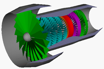
So, given that, as flyn, I haven't read regulations in detail, I have to ask: could it be legal to use some of the gas from the cartridge to turn a secondary fan that drives a main fan, bypassing some of the air around the canister case, like a turbofan engine works?

I don't know what kind of bypass ratio would be efficient at the speed of the car (1 second for 20 meters, isn't so? So, it's like 80-100 kph or what?)

Turbofan engine: the green parts are the turbo fan. The other coloured parts would be replaced by the gas canister.
Image

Of course I don't think the rules allow that. :( Anyway, those are a couple of ideas that say that if you could extract some heat from the gas or "equalize" the speed of the CO2 with the speed of the "rocket powered" car you could use the energy of the gas in a more efficient way.
Ciro

REA
REA
0
Joined: 24 Sep 2009, 08:42

Re: F1 in Schools Help

Post

Hi Brett,
Check rule 2j carefully. Your design doesn't seem to comply with the requirement for a 30 x 50 surface....

bazanaius
0
Joined: 08 Feb 2008, 17:16

Re: F1 in Schools Help

Post

I'm not so sure about the diffuser under the car - I'd rather have no car in the middle to diffuse under, as you have at the minute.

re. windtunnel - make it suck through, as your fan blades create turbulence (like a blender). If you're sucking through you're more likely to get laminar flow at the start of your car.

Belt sander isn't a bad idea - it would give you a general idea of flow even if it's not spot on.

Re. magnus - you go the point :-) If you found pretty pictures this gives you an idea of the flow structure you're looking at, although it will change slightly if the wheels are on the ground.

the nozzle on the jet is a nice idea (nozzle rather than diffuser). Worth looking at and something you could probably rig up in CFD, although not sure if your VWT software will let you. The way you discuss it involves the idea of 'entrainment' of fluid, so it might be worth looking at this. I know some research has been done where nozzles increase the thrust of pulse jets considerably, but not sure whether these improvements would transfer directly across to a rocket.

B

A13EX_f
0
Joined: 24 Sep 2009, 13:42

Re: F1 in Schools Help

Post

the drawing of the car with the cone behind the canister exit surely this gap between the canister and the cone is used to draw in extra air to create more thrust.

the same principal is used to blow up a bin bag if you simply blow into it with it sealed to your mouth it's imposible however if you hold it slightly away from you mouth and blow more air goes in as other air molecules nearby are attracted by the moving air.

sorry i dont know the exact terminology for it maybe someone else would offer more explanation.

basizeland
0
Joined: 23 Sep 2009, 09:38

Re: F1 in Schools Help

Post

I always thought that it would be better to have the car lift up and float but just recently thought that when the car lifts up it is only going to get pushed back towards the track so we are only adding drag to the car for no benefit.

With the rule 2j I know that it isn't legal so I was thinking of bringing the CO2 Canister chamber forward enough to create a 30x50 surface or add a flat 30x50 surface at the start of the sidepods on the bottom of the car but I am not sure what would be best and I am unable to test it at the moment because i don't have access to CFD until i go back to school.

I will have a try at switching the fan so that it is sucking the air through and do you think that it would be worth adding some sort of honeycomb shape to the inlet of the wind tunnel?

I am really interested in the cone behind the canister, so if anyone has suggestions i am happy to hear them.

User avatar
flynfrog
Moderator
Joined: 23 Mar 2006, 22:31

Re: F1 in Schools Help

Post

Ciro,

A wing with no AoA will have less drag than trying to add lift of df. and yes mass is the enemy not weight.

Another note on the design less is more with aero. If you don't have a need for something don't add it. A streamlined body shape is what you want with this car. Also stretching out the co2 canister as long as you can will reduce a lot of your drag.

I have been trying to find my co2 car but I think it might have been lost in one of my moves.


Ciro- I think your turbine Idea violates one of the three bastard laws of thermo.

basizeland
0
Joined: 23 Sep 2009, 09:38

Re: F1 in Schools Help

Post

Sorry but what do you mean by AoA and with the CO2 canister chamber would it be better to taper it back so that it angles the air back into a stream.

Post Reply