Suspension kinematics detail design challenges

Here are our CFD links and discussions about aerodynamics, suspension, driver safety and tyres. Please stick to F1 on this forum.
User avatar
mep
29
Joined: 11 Oct 2003, 15:48
Location: Germany

Re: 1/4 Scale R/C F1 (Regarding Chassis and suspension)

Post

Image
marcush. wrote:747 ..great CAD drawings..I´m bemused by the presence of Needle type bearings in a rocker arm svivel....that seems to me a good example for ignrant engineering (I hope this was not your work... :mrgreen: )
My reasoning:
Needle bearings do not cope well to oscillating loads
Needle bearings are not coping well with dirt (think about track,carbon dust,mechanics having to service car in the field..) and shock loads....
The failure mode of a needle bearing will also lead to a quick dnf ....so never ever I would do this ,especially in this application where you could very easily substitute the needle cage by two angular contact ball bearings with out the risk of contamination.with a decent sealing (one call with Trelleborg or even just internet research will put you quickly in the right frame of thoughts)you will not have any risk of field service issues plus you have the variable of Thrust load/end float (slack!installation stiffness,apparent hysteresis-the system is behaving differently for different starting points of a input ) covered....oh I´m again a bit too cheeky here ..please forgive...I know I´m nitpicky . :wtf:
747heavy wrote:
marcush. wrote:747 ..great CAD drawings..I´m bemused by the presence of Needle type bearings in a rocker arm svivel....that seems to me a good example for ignrant engineering (I hope this was not your work... :mrgreen: )
no it wasn´t :wink:
so feel free to pick on it, I guess there are many ways to skin a cat.
I have seen rockers with needle bearings and rockers without, both seem to work - both have won races.

I think the sealing is not really an issue, you can seal both types in a sufficient way. Normally in a Formula or Sports car, they are in a relative "clean" location, and only need to operate for a weekend, before they get serviced again.

Needle bearings seem to be quite common for ARB and pedals (brake/clutch) as well, at least I have seen them being used in such applications.

For the task at hand (1/4 model) I don´t think it´s a big issue either way, I guess I would settle for a single ball bearing, even this is probably too heavy.
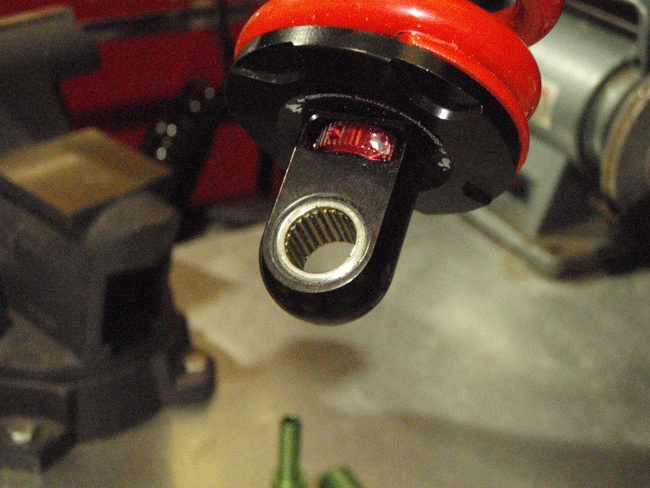
I also noticed the use of needle bearings but I don’t see it as ignorant engineering. I even thought they would be better than ball bearings. Both ball bearings and needle bearings don’t like this static load with small oscillations because the entire load is resting on a single ball and doesn’t move very much. In this case a needle bearing should be better because the contact surface of a needle is bigger than that of a ball. Also because of the small diameter of the needles (I am talking about a radial bearing now, not the one visible on the picture) they can be placed closer together so the load can be spread over more needles. Therefore a needle bearing can take higher loads than a ball bearing. Furthermore it is smaller.

The point I am very surprised about is that they use 2 axial bearings whereas I would use radial ones.
In a bell crank you usually have just radial loads, axial ones should be prevented because those can’t be transferred into the spring. How they carry the radial loads is not clear for me from this picture.

On a 1:4 car I would use a plain bearing.
They don’t care about high impulse loads or oscillating movements, they are cheap, small and reliable. Friction might be a bit higher but I don’t think it will give you any negative effect on a 1:4 car. Anyway I don’t really understand why there is such hype about reducing friction in a bellcrank bearing when you put a damper behind it anyways. The damper will cause higher friction than a plain bearing does.

marcush.
marcush.
159
Joined: 09 Mar 2004, 16:55

Re: 1/4 Scale R/C F1 (Regarding Chassis and suspension)

Post

hehe..
you both seem very optimistic about debris and dirt...I´m not...carbonfibre dust is quite awful in getting inside everything and destroying (degrading everything in short time)
So my idea of having something sealed and replaceable in the field as a unit in case of failure is a major design consideration .
Without a doubt Mep is right with him mentining a bushing ,this will in effect give you at least a slowly increasing tolerance with overload and wear but not a
unpleasant behaviour with dirt ingress blocking needles.

A short reference to a a matrix from bearing manufacturers reveal no real solution is available but it seems to be a better bet to not have a needle cage and instead opt to have just needles filling between inner and outer bearing surface...still the question of minimizing axial float without rising friction is a question here..
I think I would go for a full metal bushing solution in this and have the surfaces DLC coated to supply a wear resistant surface .Quite demanding in fabrication but this would do away with weight,would be without a doubt the most compact installation ,stiff as it can be and a slab of klueber lubricant would be all thats needed for installation...
:mrgreen:

User avatar
747heavy
24
Joined: 06 Jul 2010, 21:45

Re: 1/4 Scale R/C F1 (Regarding Chassis and suspension)

Post

@marcus
still not sure, why you think that one can´t seal a needle bearing in a sufficient way?
and
allmost any engine rocker (valvetrain) uses needle bearings - why? any thoughts

there are handy combinations of radial/axial needle bearings, ready as press in without the need of an hardned outer race. Presses straight into a aluminium rocker.
http://www.pegasusautoracing.com/2010/143.pdf

as for the model
just make the rocker out of ceramics - problem solved
we do love technology - or not? Who said it was meaned to be easy. :)

@ mep
there are normally 3 needle bearings in the rocker, 1x radial and 2x axial,
I think the radial one, is not so easy to see on this cut away.

but alternativly you could use such a combined bearing:
Image

I guess, you will wonder about this practice, even more:
Image
"Make the suspension adjustable and they will adjust it wrong ......
look what they can do to a carburetor in just a few moments of stupidity with a screwdriver."
- Colin Chapman

“Simplicity is the ultimate sophistication.” - Leonardo da Vinci

marcush.
marcush.
159
Joined: 09 Mar 2004, 16:55

Re: 1/4 Scale R/C F1 (Regarding Chassis and suspension)

Post

ok lets leave it at that and transfer the discussion to the engineering threads to keep on topic here .


I´d think if you would really want a rocker -plain bushing is the way to go on quarterscale rockers AND reduce the amount of couplings to keep installtion stiffness as high as possible(reason for flexures)

User avatar
mep
29
Joined: 11 Oct 2003, 15:48
Location: Germany

Re: 1/4 Scale R/C F1 (Regarding Chassis and suspension)

Post

Sad you want to stop the conversation when it starts to become interesting.
Ok we kinda solved the issue for the 1:4 car but what do you think about the use of plain bushings on a bigger car?
Regarding oscillating movement and force pulses the bushing is better but what do you think about friction (stick slip, initial friction)?
Do you agree the theory that you don’t need to care about it because the damper causes anyway lots of friction?

User avatar
mep
29
Joined: 11 Oct 2003, 15:48
Location: Germany

Re: 1/4 Scale R/C F1 (Regarding Chassis and suspension)

Post

Yes nice idea.
I was just refering to the point about sealing which shouldn't be a big problem. For sure carbon dust can be very abrasive but it's just transported by air and not under pressure. I can think of much more demanding machines to seal.

User avatar
mep
29
Joined: 11 Oct 2003, 15:48
Location: Germany

Re: Suspension kinematics detail design challenges

Post

I don’t think we should exclude anything from the beginning on everything regarding suspension is just fine. It’s similar like the car topics which reached over hundred pages talking about (almost) every aspect of the car. Thinks like chamber, ackerman, anti dive/squat can’t be excluded because they are way to essential for a good design.

marcush.
marcush.
159
Joined: 09 Mar 2004, 16:55

Re: Suspension kinematics detail design challenges

Post

I agree in that these functionalities or characteristics are very important as design constraints (for example -a flexure is not really working with big angular movements (short wishbones and much suspension travel) but if we open the discussion
to the geometry here we might easily get lost...but i understand your reasoning.

User avatar
mep
29
Joined: 11 Oct 2003, 15:48
Location: Germany

Re: 1/4 Scale R/C F1 (Regarding Chassis and suspension)

Post

First of all somebody has to come and post anything about geometry and when you than think it doesn't fit or goes to deep we can move it to a separate topic.
First we can collect things here.

Don't let us lose the context now, that’s the point where we got stuck:
mep wrote:Ok we kinda solved the issue for the 1:4 car but what do you think about the use of plain bushings on a bigger car?
Regarding oscillating movement and force pulses the bushing is better but what do you think about friction (stick slip, initial friction)?
Do you agree the theory that you don’t need to care about it because the damper causes anyway lots of friction?

riff_raff
riff_raff
132
Joined: 24 Dec 2004, 10:18

Re: Suspension kinematics detail design challenges

Post

Consistent end moment frictions in suspension joints is a very serious concern because it can affect dampening rates.

And marcush is correct, needle bearings are a bad choice for oscillating joints like in a suspension rocker. They must be larger and heavier than a plain bearing for the same load capacity. They will quickly fail if subjected to reversing loads. They must be sealed and are sensitive to dirt and moisture. They have limited fatigue life due to the fact that the same few rollers and raceway section are constantly subjected to load in an oscillating joint. And most importantly, in an oscillating joint, the static breakaway end-moment frictions in a needle bearing and plain bearing are the same, since both are briefly operating in boundary contact conditions when the joint rotation changes direction and its angular velocity is zero.

The best suspension joint is one that has zero friction losses and has totally consistent stiffness/dampening under all conditions. ......Like a flexure.

Also, as a rule of thumb, rotary joints should be mounted in double shear whenever possible to maximize stiffness. A cantilevered rocker shaft with needle bearings will likely have lots of shaft deflections and will result in edge loading of the high aspect ratio needle rollers.

Regards,
riff_raff
"Q: How do you make a small fortune in racing?
A: Start with a large one!"

marcush.
marcush.
159
Joined: 09 Mar 2004, 16:55

Re: Suspension kinematics detail design challenges

Post

riff raff ,
this is exactly my experience.I did a bit of research and testing with regard to needle bearings in oscillating movements and my findings were:

even with a very tight seal (the bearing originated from a throttle blade bearing )the needele bearing was unabale to survice even though the maximum loads where below the allowed forces by a factor of 10...The water ingress was killing the needles ,not the dirt.A needle bearing just able to bear the loads with safety factor of 2 but made from material with better corrosion resistance survived all test
(but we introduced a second seal(more fiction again)to slow down the conatmination of the bearing.I did a lot of non distructive examination (with CT)to see how things
degarded..In this the first thing to observe was: Grease accumulated away from the needles...so the needles carced out paths were almost nill lubricant was were it was needed.With 1 huge temperature shock - one single water pass on the proving ground -and the bearing housing at something like 100°C it was possible to get water into the housing (differnt pressure rise with temperature was the obvious indicator for something influencing pressure rise inside -not just air but also water- )Storing of the part -no movement was contributing more than anything else
to the bearing detoriating (rust).
The Bearings did not like to be turned without load ! so mechanical testing on the bench (endurance) killed the needles ,whereas putting a load onto the bearing helped their life...

RH1300S
RH1300S
1
Joined: 06 Jun 2005, 15:29

Re: Suspension kinematics detail design challenges

Post

riff_raff wrote:The best suspension joint is one that has zero friction losses and has totally consistent stiffness/dampening under all conditions. ......Like a flexure.

Regards,
riff_raff
Just as long as you KNOW it flexes in EXACTLY the same place every time surely? I would have thought a joint like this could flex slightly differently depending on the direction of the forces coming into it. Even a millimetre out of place would change the instantaneous roll centre.

marcush.
marcush.
159
Joined: 09 Mar 2004, 16:55

Re: Suspension kinematics detail design challenges

Post

I know from Andy Wallace that Dyson used redesigned wishbones without flexures
on their MG-Lolas in USA some time ago as these where contributing to unstability under braking ,due to the flexures neded to be quite long to allow enough suspension movement..
the cure was to go back to sphericals to mount the wishbones....

User avatar
mep
29
Joined: 11 Oct 2003, 15:48
Location: Germany

Re: Suspension kinematics detail design challenges

Post

So the question remains open what is the best bearing for a rocker?
I would put them in this order:
1. plain bushing
2. needle bearing
3. ball bearing

I wonder why I usually see ball bearings used in this application.
riff_raff wrote:Consistent end moment frictions in suspension joints is a very serious concern because it can affect dampening rates.
For sure friction does affects damping but does it hurt?
The damper friction probably is magnitudes higher than the friction in the bearings so I don’t think the actual amount of bearing friction is important.
What I do see as problem is the higher friction when the movement starts. For high frequency, low amplitude movements the rocker probably will not move at all. This possible can be balanced by lower damping friction on the initial movement.
And most importantly, in an oscillating joint, the static breakaway end-moment frictions in a needle bearing and plain bearing are the same, since both are briefly operating in boundary contact conditions when the joint rotation changes direction and its angular velocity is zero.
Hmm first time I hear this and I am not convinced of it.
The low friction of a plain bearing is caused by a liquid film between shaft and housing (fluid friction). This film needs some velocity/movement to build up. So in mainly static or oscillating conditions it will have dry friction or mixed friction. A ball or cylinder will at least have rolling friction. The bigger balls of a ball bearing possible have lower initial friction than low diameter needles. Maybe that’s the reason why ball bearings are so often used in this position. Anyway as said above friction shouldn’t be the problem so is plain bearing the way to go?

DaveW
DaveW
239
Joined: 14 Apr 2009, 12:27

Re: Suspension kinematics detail design challenges

Post

mep wrote:For sure friction does affects damping but does it hurt?
The damper friction probably is magnitudes higher than the friction in the bearings so I don’t think the actual amount of bearing friction is important.
Friction doesn't hurt, so long as it is consistent & accounted for in the set-up. The problem with plain bearings, in my experience, is that friction varies with load, & the rockers in an open wheeled vehicle tend to be highly loaded. I have seen a vehicle with plain bearing rockers that really didn't require dampers....

As a foot to earth, I have just looked up the total friction (links, rocker, damper, etc.) in the suspension of an F3 vehicle (no flexures), selected more-or-less at random. It was around 120 N at the front axle, & 150 N at the rear axle (both per side). I would expect the damper contribution to be no more than 1/3 of the total (although that can vary with charge pressure & side load/bending moment).