2 stroke thread (with occasional F1 relevance!)

All that has to do with the power train, gearbox, clutch, fuels and lubricants, etc. Generally the mechanical side of Formula One.
manolis
manolis
107
Joined: 18 Mar 2014, 10:00

Re: 2 stroke thread (with occasional F1 relevance!)

Post

Hello Pinger.

You write:
“CITS has two patent applications it seems. One each for the flap and by-pass valve.
Previous crosshead marine engines have wet sump covered I guess so no patents there. CITS as I see it is a variation on a theme and only the valve patents prevent anyone productionising it if they wanted to. Skip his valves and go straight to crosshead and wet sump - if you want. Are his valves really that much better than simple reeds? Does his increase in crankcase compression from 1.4-1.5:1 to 1.6:1 really incur throttling losses that justify or need a by-pass valve?”


The core idea behind the CITS seems to be the reduction of the pumping loss when a 2-stroke operates at lower revs / light loads (i.e. wherein the 2-strokes suffer).


CITS tries to bring to the 2-stroke engines what the Attkinson / Miller cycle brings to the 4-stroke engines (many of the modern fuel-efficient 4-strokes use, in a significant degree, the Miller cycle; for the basic Miller patent click on http://www.pattakon.com/tempman/Miller_patent.pdf )


At light loads the pumping loss is a significant part of the indicated power.
With the PatAir of pattakon (more at http://www.pattakon.com/pattakonHydro.htm ) the 4-stroke avoids the sub-pressure during the induction, and so it reduces the relative pumping loss (an advantage that comes together with other advantages like the lower temperature of the cycle etc).

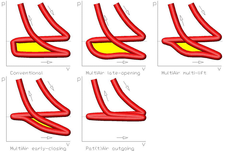
The PatAir of pattakon is actually a slight modification of the MultiAir / TwinAir system of FIAT - Chryshler / INA – Schaeffler.
The modification is slight, however the difference it brings is big / significant because it offers an infinity of additional more-fuel-efficient modes to the modes already available with the MultiAir / TwinAir of FIAT :
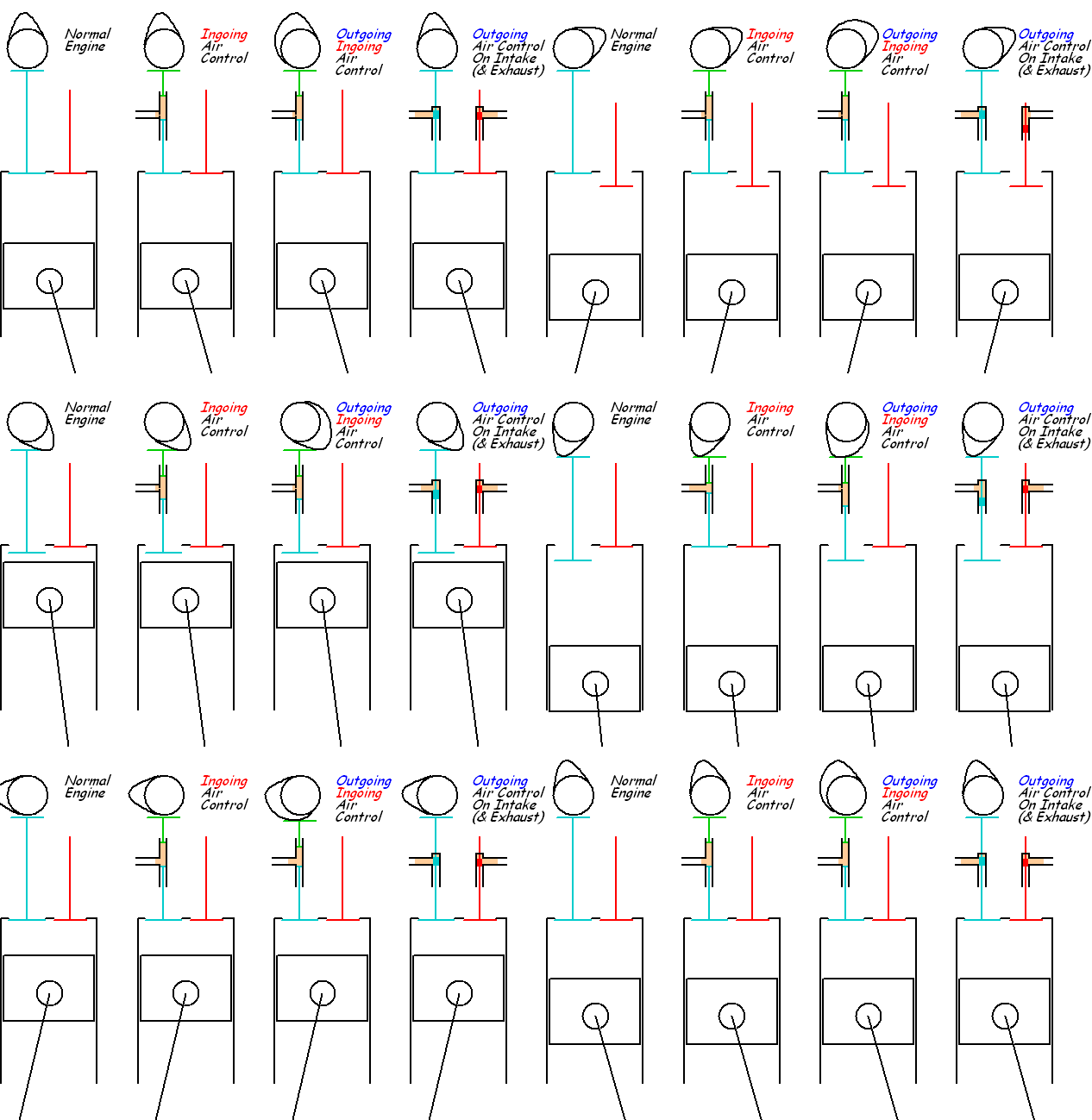
Image

The following plot helps to get the difference:
Image


In the PatTwo patent (post in page #113 and page #116) it is explained where the CITS engine of Basil Van Rooyen fails to do what it is supposed it should do.

The variation of the total volume of the two cooperating spaces under the two pistons of the CITS engine spoils the operation of the engine at lower revs / light loads, i.e. exactly where it is supposed it brings the best improvement.

As noted in U.S. Pat. No. 8,683,964 of Basil Van Rooyen (CITS):

"In practice a butterfly valve maybe provided in the inlet conduit, not for throttle control but for the purpose of idle setting. Above these very slow idle speeds, this butterfly valve would open fully, and the engine speed and power would be controlled solely by the by-pass valve, and not by the butterfly valve or any other throttle arrangement upstream of the bifurcation point.”.


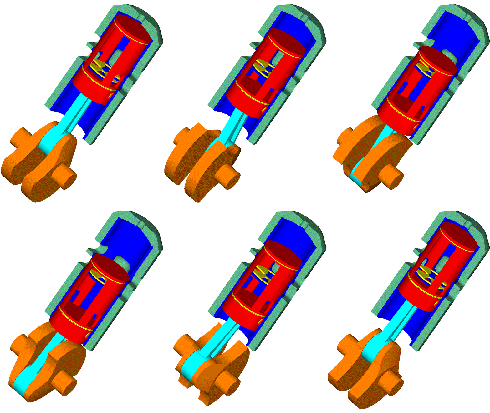
The PatTwo design does not need such a throttle valve because the sum of the volumes of the two cooperating spaces is constant (either in the single combustion chamber / conventional version, or in the double acting piston / harmonic version; more at http://www.pattakon.com/pattakonPatTwo.htm ) .


The difference gets clearer if you think the case a PatTwo engine:
Image

is running at idling (or at light load / low revs), with the passageway between the two spaces, above and below the “separator” (inside the piston), communicating freely.

Isn’t it the Miller cycle applied in a 2-stroke?

(What happens in a 4-stroke “unlimited” (as the PatAir) Miller at idling / light loads? The fresh air or mixture enters into the cylinder through the intake valves and then (as the piston performs its “compression stroke”) most of the air or mixture entered in the cylinder returns back to the intake manifold though the still open intake valves (LIVC), without creating significant subpressure or pumping losses).


The PatTwo is good not only for light loads / lower revs.

At higher revs / heavier loads the PatTwo design offers new opportunities, like the “variable” crankcase “dead volume": depending on how much open or close is the throttle (or control) valve, the crankcase behaves as having from quite small to quite large dead volume. With a tuned exhaust . . .

Thanks
Manolis Pattakos

Muniix
Muniix
14
Joined: 29 Nov 2016, 13:29
Location: Sydney, Australia

Re: 2 stroke thread (with occasional F1 relevance!)

Post

Was thinking given a well designed hybrid dual cranktrain bottom end how much effort would be needed to switch the cylinder housings and integrated Bishop valve Jet Ignition head & liner with a Jet ignition two stroke system it would need a 98 mm bore as minimum and a 66 mm stroke as maximum, the clearence before it hits the TS³ Steering and suspension system lower arms being a constraint. The piston motion should be convenient for two stroke, uni-flow may be possible the normal bore size is 120.65 mm, with support down to 98 gives clearence. Interchangeable two / four stroke engine!

Reducing pumping losses

Scavenging with the Bishop valve was found to be excellent, with only 2% exhaust gas residuals using 20 degrees overlap, on the F1 overlap was under 40 and 30 was ok. This means you can perform scavenging while the piston is mostly stationery at or near TDC. This helps filling the compression volume with fresh charge before it descends. With phasing some interesting possibilities arise as you can move scavenging +/- TDC to achieve Miller, Aitkenson or Otto cycles. Investigating the inlet and exhaust pressure during phasing gives possibilities not previously available.

There being no interference as there would be with piston and poppet valves. Using the Sensata cylinder pressure only sensor and the inlet pressure sensor with electronic throttle to control the inlet pressure engine load can be performed mostly with phasing.

Engine control strategies can get interesting, achieving fine control of intake and exhaust flows and their kinetic energy used for turbulence to assists combustion speed.

Delayed valve timing with the unobstructed flow provides very high intake velocities in the over rev range the cranktrain and valve are capable of and with gas compressibility super filling the cylinder.

At slow speed one can advance the valve timings retaining some EGR within ​the cylinder as scavenging completes early along with intake closing and exhaust opening, there not being high pressure combustion at low loads do no real power loss there. The cylinder pressure sensor data giving you good information to optimise phasing control.

A similar phasing valve and control as used by Ducati on the Testastretta DVT dual spark 1198 engine as the torsional load on the phaser is low, likely lower than the Desmodromic valve gear.

Including bearing friction models and others into virtual sensor data for the the ECU to use in its fully closed loop operation. You can keep the engine operating at peak TE efficiency and reduce mechanical losses producing most effective rotational​ torque. Calculating the Imep one can display on the Dash if one wanted to like rpm gauge with the Bmep in a different colour.

The engine management software and hardware is moving along well using NVIDIA platform, but want to move to Arm/Mali asap, their new Automotive vision AI platform just released suits purpose. Plenty of Gigaflops for the PDE equations.
Last edited by Muniix on 16 May 2017, 08:58, edited 3 times in total.

J.A.W.
J.A.W.
109
Joined: 01 Sep 2014, 05:10
Location: Altair IV.

Re: 2 stroke thread (with occasional F1 relevance!)

Post

Muniix wrote:
16 May 2017, 06:18
Scavenging with the Bishop valve was found to be excellent, with only 2% exhaust gas residuals using 20 degrees overlap on the F1 it overlap was under 40 and 30 was ok. This means you can perform scavenging while the piston is mostly stationery at or near TDC. This helps filling the compression volume with fresh charge before it descends. With phasing some interesting possibilities arise as you can move scavenging +/- TDC to achieve Miller, Aitkenson or Otto cycles. Investigating the inlet and exhaust Pressure during phasing gives possibilities not previously available.

There being no interference as there would be with piston and poppet valves. Using the Sensata cylinder pressure only sensor and the inlet pressure sensor with electronic throttle to control the inlet pressure engine load can be performed mostly with phasing.

Engine control strategies can get interesting, achieving fine control of intake and exhaust flows and their kinetic energy used for turbulence to assists combustion speed.

Delayed valve timing with the unobstructed flow provides very high intake velocities in the over rev range the cranktrain and valve are capable of due to gas compressibility super filling the cylinder. At slow speed one can advance the valve timings retaining some EGR within ​the cylinder as scavenging completes early along with intake closing and exhaust opening, there not being high pressure combustion at low loads. The cylinder pressure sensor data giving you good control...
Ok Marc, you're still singing the Bishop's praises sans hard data ( 'cept the FIA banned it, which stands to its merit, IMO)..

But all sad eulogies aside, would this Bishop rotary valve flow well enough to support a useful BMEP via the 2T cycle?
Run that one through your computational synthesis modelling & get back to us.. other-wise, do try & stay on topic..

& for T-C, your assumption that a 2T cylinder of any capacity larger than 125cc is unable to support useful BMEP,
is somewhat biased.. fact, is no really meaningful effort has been put into researching similar N/A 2T 250cc+ cyls..
in recent times ..but Ricardo did do some big SI 2T cyls, & 'only' got to ~20 bar, with his Crecy test unit..
"Well, we knocked the bastard off!"

Ed Hilary on being 1st to top Mt Everest,
(& 1st to do a surface traverse across Antarctica,
in good Kiwi style - riding a Massey Ferguson farm
tractor - with a few extemporised mod's to hack the task).

Muniix
Muniix
14
Joined: 29 Nov 2016, 13:29
Location: Sydney, Australia

Re: 2 stroke thread (with occasional F1 relevance!)

Post

J.A.W. wrote:
16 May 2017, 08:42
Muniix wrote:
16 May 2017, 06:18
Scavenging with the Bishop valve was found to be excellent, with only 2% exhaust gas residuals using 20 degrees overlap on the F1 it overlap was under 40 and 30 was ok. This means you can perform scavenging while the piston is mostly stationery at or near TDC. This helps filling the compression volume with fresh charge before it descends. With phasing some interesting possibilities arise as you can move scavenging +/- TDC to achieve Miller, Aitkenson or Otto cycles. Investigating the inlet and exhaust Pressure during phasing gives possibilities not previously available.

There being no interference as there would be with piston and poppet valves. Using the Sensata cylinder pressure only sensor and the inlet pressure sensor with electronic throttle to control the inlet pressure engine load can be performed mostly with phasing.

Engine control strategies can get interesting, achieving fine control of intake and exhaust flows and their kinetic energy used for turbulence to assists combustion speed.

Delayed valve timing with the unobstructed flow provides very high intake velocities in the over rev range the cranktrain and valve are capable of due to gas compressibility super filling the cylinder. At slow speed one can advance the valve timings retaining some EGR within ​the cylinder as scavenging completes early along with intake closing and exhaust opening, there not being high pressure combustion at low loads. The cylinder pressure sensor data giving you good control...
Ok Marc, you're still singing the Bishop's praises sans hard data ( 'cept the FIA banned it, which stands to its merit, IMO)..

But all sad eulogies aside, would this Bishop rotary valve flow well enough to support a useful BMEP via the 2T cycle?
Run that one through your computational synthesis modelling & get back to us.. other-wise, do try & stay on topic..

& for T-C, your assumption that a 2T cylinder of any capacity larger than 125cc is unable to support useful BMEP,
is somewhat biased.. fact, is no really meaningful effort has been put into researching similar N/A 2T 250cc+ cyls..
in recent times ..but Ricardo did do some big SI 2T cyls, & 'only' got to ~20 bar, with his Crecy test unit..
What is said about time and ideas. I just edited that post after checking no one had posted after it and put in a concept of supporting Two stroke on the base platform.

... Minds think alike.

Please refresh and re read my previous edited post.

Just waiting for someone dead line to be over, next week a major printing conference is on in Melbourne. Who works at Memjet now one may ask!!!
Real question is how many work at Memjet now.

manolis
manolis
107
Joined: 18 Mar 2014, 10:00

Re: 2 stroke thread (with occasional F1 relevance!)

Post

Hello all.


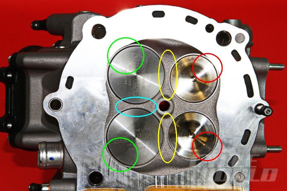
Here is a Ducati Panigale cylinder head:

Image

The arrangement of the poppet valves puts several restrictions / limitations in the gas flow, it also spoils the “scavenging” of the combustion chamber during the overlap (piston near TDC, all valves open), it also worsens the combustion.

At the area in the green circles, the intake valves are too close to the cylinder wall.

At the area in the cyan ellipse, the one intake valve restricts the flow of the other intake valve.

During the overlap, in the area shown by the yellow ellipses the intake and the exhaust are short-circuited: a good part of the gas entering through the intake valves cannot help passing directly to the exhaust. The residual gas reduces in expense of unburned mixture escaping towards the exhaust (emissions, fuel consumption).

The big valves with the necessarily large valve lifts require deep pockets on the piston crown:

Image

When the piston is at the TDC the combustion chamber is anything but compact or smooth.

A good part of the mixture is compressed in the valve pockets.
The flame has to travel from the spark plug at the center of the cylinder till the cylinder walls, some 60mm away.
The flame extends at only two dimensions (the third dimension is only 5mm, or so, when the piston is at its TDC) which reduces the rate the combustion proceeds, increases the required spark advance and increases the thermal losses (lower BTE).


Despite all these, it is a great engine:

Quote from the Cycleworld:

“Ducati's 1299 Superleggera Is The Most Powerful Twin-Cylinder Production Bike It's Ever Produced

By Bradley Adams

The evolution of Ducati’s superbike continues with the official release of the new 1299 Superleggera. Complete with carbon fiber frame, wheels, and fairings, Ducati claims that this is the most technologically advanced production superbike, ever. And they’re right.”


The most powerful Twin in production, ever, and the most expensive Ducati, ever, uses only one centrally located spark plug and no variable valve timing.

And proves in practice that their super-over-square designs (1.91:1 stroke to bore ratio) have significant advantages to offer, provided the intake and exhaust valves can operate at higher revs.


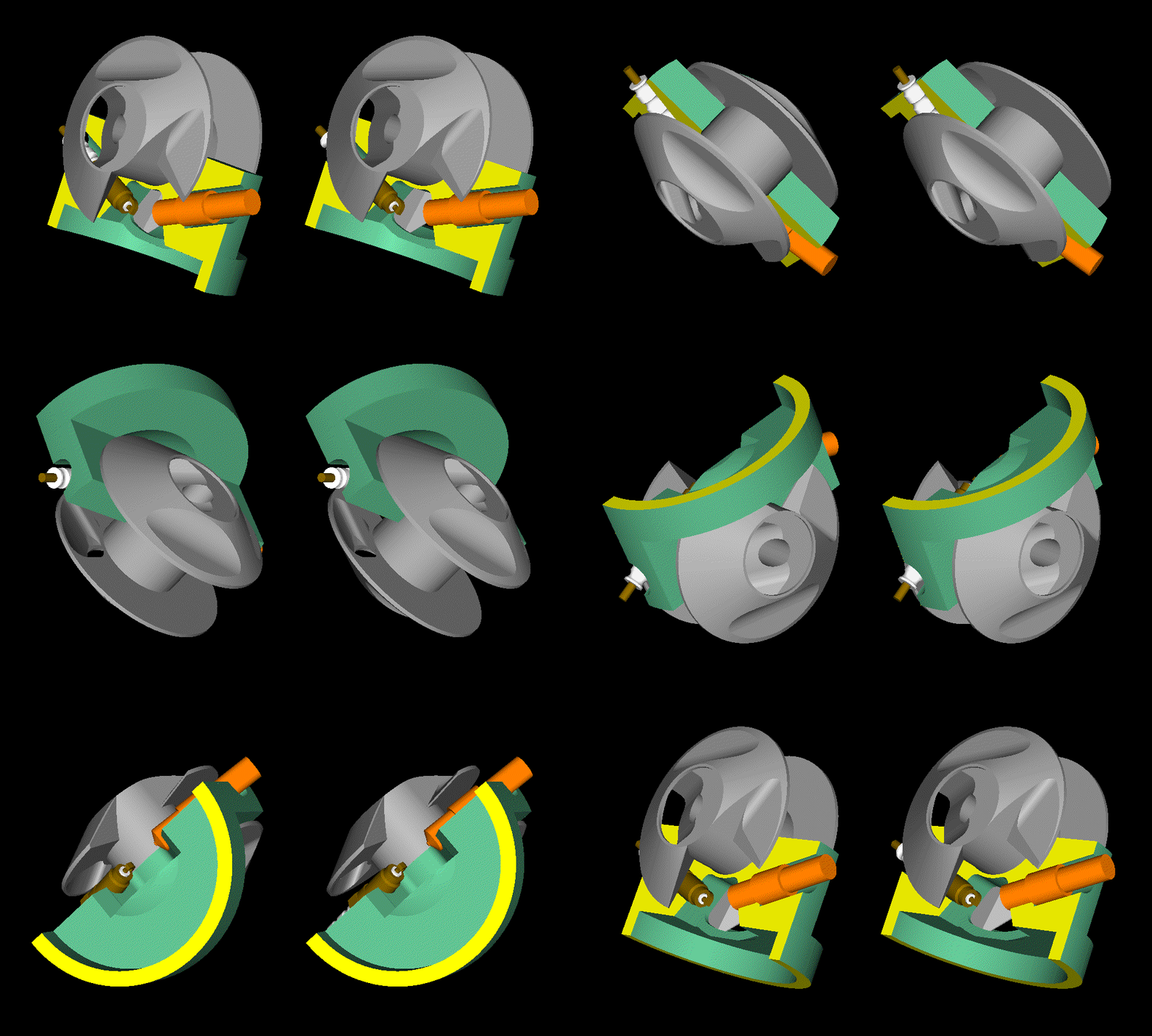
With its cylinder head having neither rev limit, nor frictional losses, the PatRoVa rotary valve has a good advantage from the beginning.

Why?

Because the power previously consumed to drive the valve train, now is available on the crankshaft.

And as the revs increase and the forces increase with revs square, this power saving is anything but insignificant.

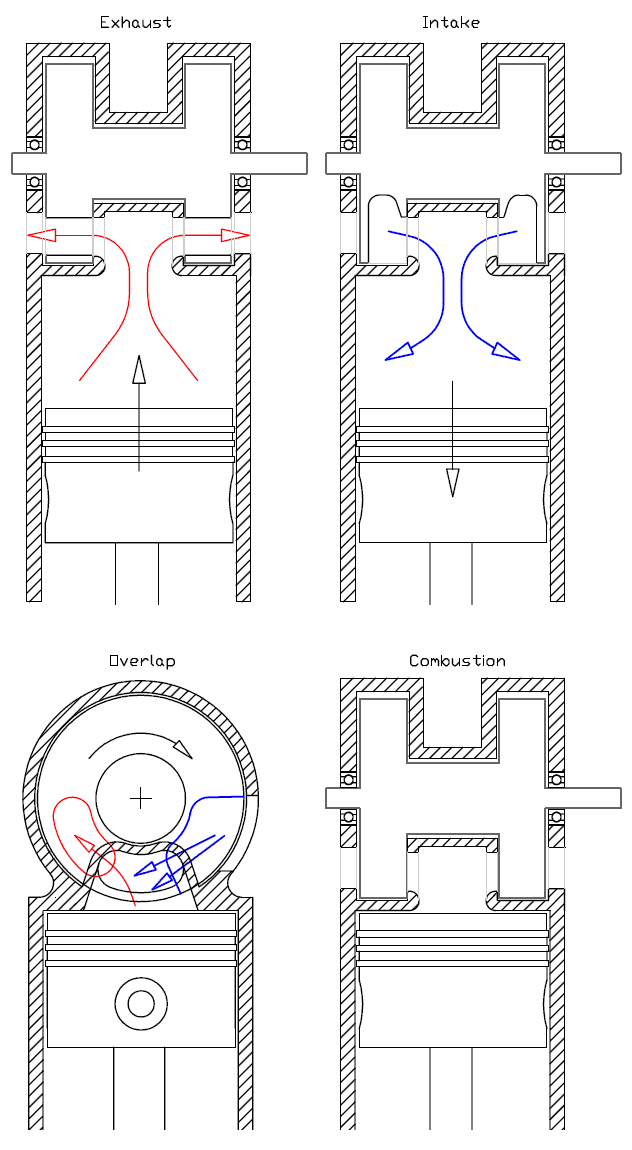
The form of the combustion chamber and the way the ports open and close gives another significant advantage to the PatRoVa rotary valve engine:

Image

because during the overlap,
from the one end of the combustion chamber the burnt gas exits (red port on the rotary valve) while from the other end of the combustion chamber (blue port on the rotary valve) fresh gas / mixture enters scavenging the combustion chamber.
With the inlet and exhaust passages remaining at a significant distance from each other, the “short-circuiting” between the intake and the exhaust is too difficult to happen.

Image

Not to mention the unloaded bearings of the PatRoVa rotary valve, the absence of hot spots in the combustion chamber, the “built-in” recycling of any gas leakage, etc, etc.


More at http://www.pattakon.com/pattakonPatRoVa.htm

Thanks
Manolis Pattakos

Pinger
Pinger
9
Joined: 13 Apr 2017, 17:28

Re: 2 stroke thread (with occasional F1 relevance!)

Post

J.A.W. wrote:
16 May 2017, 01:53
I think you'd best have another look P, since that dyno chart shows the 3-3 pipes are always ahead of the 3-1 on TQ,
& thus will never give less HP, anywhere in the rpm range.. ..albeit it is a CVT snowmobile chart, though tests on the
Kawasaki triple motorcycles show the same response, with a well-designed pipe/tune combo the 3-3 always wins..
Nope! There is no guarantee or proof that the torque remains below 6500 rpm.
Possibilities as to why the plot begins at 6500 rpm are: the sled was clutched at that speed (and if it was, it was for a reason...); it would not pull the dyno below 6500 rpm. Otherwise, why not begin the plot from idle speed?
J.A.W. wrote:
16 May 2017, 01:53

Here (linked below) is a dyno chart of a tuned Kawasaki 750 with 3-1, it worked well with the tune, but still lost up top..

www.kawi2strokes.com/forum/viewtopic.ph ... 6&start=20
I think we are at cross purposes here. What I'm seeing is an exp' chamber being fed by three pipes, the only purpose the three headers serve is to feed the chamber.
What I mean by 3-1 is cross-charging where the headers feed to a cylinder closing its ex' port a +ve pulse from the next cylinder in the firing sequence as it opens its ex' port. For a triple, the ex' duration has to be sufficient to permit that overlap and the headers short enough to convey the pulse in the short time available. When I say 'short' header lengths - I mean bore spacing. And what follows (in the way of pipe work) the manifold is of little consequence (though a divergent cone will likely feature) but will serve only the cylinder that created the pulse (as opposed to one further up the firing sequence).

Thus, the arrangements TC mentioned are of no use. Triples must employ 120 deg between firing, fours must fire at 90 deg intervals.

Pinger
Pinger
9
Joined: 13 Apr 2017, 17:28

Re: 2 stroke thread (with occasional F1 relevance!)

Post

manolis wrote:
16 May 2017, 04:52
The core idea behind the CITS seems to be the reduction of the pumping loss when a 2-stroke operates at lower revs / light loads (i.e. wherein the 2-strokes suffer).

At light loads the pumping loss is a significant part of the indicated power.
My understanding is that at low (throttled) loads the 2T barely suffers from throttling losses, it is the 4T that is hamstrung by them.
Compare the 'pumps' in question. One operates at between 1.4:1 - 1.6:1 (at best), the other circa 10:1 compression ratios. Hence the difference.

At the other end of the load factor equation, the air work for the 2T is higher than the 4T as the 4T has the more efficient 'pump' and less obstructive flow path. More true at higher rpm (though resonant tuning rescues the 2T here).
But, for road use, efficiency at part load is of great importance. A quick perusal of how 4T is now operated in road use steady speed cruising (high gearing, low rpm, relatively unthrottled - but requiring flexible transmissions) points to this. Contrast that with how 2T is configured for outboards ie, relatively high rpm, throttled cruising.

Tommy Cookers
Tommy Cookers
621
Joined: 17 Feb 2012, 16:55

Re: 2 stroke thread (with occasional F1 relevance!)

Post

[quote=Pinger].......I think we are at cross purposes here. What I'm seeing is an exp' chamber being fed by three pipes, the only purpose the three headers serve is to feed the chamber.
What I mean by 3-1 is cross-charging where the headers feed to a cylinder closing its ex' port a +ve pulse from the next cylinder in the firing sequence as it opens its ex' port. For a triple, the ex' duration has to be sufficient to permit that overlap and the headers short enough to convey the pulse in the short time available. When I say 'short' header lengths - I mean bore spacing. And what follows (in the way of pipe work) the manifold is of little consequence (though a divergent cone will likely feature) but will serve only the cylinder that created the pulse (as opposed to one further up the firing sequence).
Thus, the arrangements TC mentioned are of no use. Triples must employ 120 deg between firing, fours must fire at 90 deg intervals.[/quote]

Saab gave an SAE paper on the 96 the (DKW copy) 3 cylinder 2 stroke
a key point was that only 3 cylinders allowed a manifold good for performance and a practical length for (cast)production and use

the arrangements I mentioned were for a notional NA F1 eg to avoid needing 8 or 9 or 12 or 16 or 18 expansion chambers
of course I didn't mention that 2 or 3 or 4 simultaneous firing cylinders would still need their 'single' chamber to have a '2x or 3x or 4x' volume

18 cylinders of a size near 125 Aprilia design would have enough port area for a notional 1000 hp 2.4 litre
and a prohibitive consumption as would a 2 stroke in Moto GP ?
Last edited by Tommy Cookers on 16 May 2017, 11:28, edited 1 time in total.

Pinger
Pinger
9
Joined: 13 Apr 2017, 17:28

Re: 2 stroke thread (with occasional F1 relevance!)

Post

Tommy Cookers wrote:
16 May 2017, 11:02


Saab gave an SAE paper on 'their' (ie DKW copy) 3 cylinder 2 stroke
a key point was that only 3 cylinders allowed a manifold good for performance and a practical length for (cast)production and in use
For 90deg firing fours the manifold can be externalised (or incorporated into the V as in the Bubbleback V4 Evinrudes).
Document below explains the concept.
These arrangements though, aren't for very high revving engines. Applied to engines topping out at around 6000rpm though, they are both compact and maintain the useful +ve pulse at a beneficial crank angle over a wide rpm range. Even at very low rpm, the +ve pulse arrives at around 40-45deg ABDC. Contrast that with exp' chambers which at the same rpm will be returning the pulse well before BDC.
The pulses aren't anything like as 'strong' as with exp's though so peak BMEP is lower - circa 8bar. Still useful given their other virtues. For absolute power exp's are still king.

http://members.iinet.net.au/~pauldawson ... hausts.PDF

Muniix
Muniix
14
Joined: 29 Nov 2016, 13:29
Location: Sydney, Australia

Re: 2 stroke thread (with occasional F1 relevance!)

Post

Jet ignition improves gasoline/petrol engines low load efficiencies.
With 2T compression ratio can be increased, the extra air mass required reduces thermal load. There was a two stroke Jet ignition research engine built.

The 4T gasoline/petrol engines at low load efficiency, first through increasing the compression ratio by 2 points or more and second by dethrottled operation reducing pumping losses pushing the FE to 2.3 and maintaining combustion stability, low coefficient of variance. This may be improved further as knowledge and experience is gained. I assume that engines now need larger exhaust valves maybe same as inlet now.

The reduced thermal and peak pressure forces allow lighter engines to be constructed.

Such as like the Polimotor 2
Where most of the engine is made out of CFRP using advanced polymers from Solvay​, mostly PEEK, PEAK, for the hot areas.
Including oil pump housing, valve guides, fuel rail, inlet runners... lots of components.

The head is alloy and liner as well as about 40 metal components placed into the mould before squeeze cast.

They are experimenting with nickel plasma coated CFRP for the liner. With Jet ignition this would be far more viable, has run with rods and plastic piston skirts​. Turbo compressor housing polymer also. 2.3 litre 300+ HP race motor.

Image
The advantages to injection over moulding using CFRP is the energy needed, the components are near net shape needing less machining, the mould lasts longer. They are lighter and the engine comes up to temperature faster meeting emmisions earlier from cold start.
Cheaper to make for lower production volumes.

Muniix
Muniix
14
Joined: 29 Nov 2016, 13:29
Location: Sydney, Australia

Re: 2 stroke thread (with occasional F1 relevance!)

Post

Maybe a pressure wave supercharger to provide the intake pressure on a two stroke engine, after the first couple of cycles on start would be running well. Make a good research project. Integration into the packaging some novel way. High charge pressure with EGR if needed with TJI and conventional HP direct injection. Two stroke engines are pressure wave engines. There must be a clever meeting of these two systems that is an improvement and simple. A through flow PWS not the Hyprex style with inlet and exhaust at opposite ends.

Also on calling Polaris Swiss Auto about the Hyprex PWS seems Polaris hasn't just shut down Victory, Mission motors they have sold off the IP assets and components. So no more PWS availability from Swiss Auto. That is a shame.
No reply from the German company that has bought it.

Tommy Cookers
Tommy Cookers
621
Joined: 17 Feb 2012, 16:55

Re: 2 stroke thread (with occasional F1 relevance!)

Post

regarding firing 2 or 3 or 4 cylinders simultaneously
the crankcase is of course common for each set of cylinders - saving much bulk and weight and bearing etc friction

J.A.W.
J.A.W.
109
Joined: 01 Sep 2014, 05:10
Location: Altair IV.

Re: 2 stroke thread (with occasional F1 relevance!)

Post

Pinger wrote:
16 May 2017, 10:29
J.A.W. wrote:
16 May 2017, 01:53
I think you'd best have another look P, since that dyno chart shows the 3-3 pipes are always ahead of the 3-1 on TQ,
& thus will never give less HP, anywhere in the rpm range.. ..albeit it is a CVT snowmobile chart, though tests on the
Kawasaki triple motorcycles show the same response, with a well-designed pipe/tune combo the 3-3 always wins..
Nope! There is no guarantee or proof that the torque remains below 6500 rpm.
Possibilities as to why the plot begins at 6500 rpm are: the sled was clutched at that speed (and if it was, it was for a reason...); it would not pull the dyno below 6500 rpm. Otherwise, why not begin the plot from idle speed?
J.A.W. wrote:
16 May 2017, 01:53

Here (linked below) is a dyno chart of a tuned Kawasaki 750 with 3-1, it worked well with the tune, but still lost up top..

www.kawi2strokes.com/forum/viewtopic.ph ... 6&start=20
I think we are at cross purposes here. What I'm seeing is an exp' chamber being fed by three pipes, the only purpose the three headers serve is to feed the chamber.
What I mean by 3-1 is cross-charging where the headers feed to a cylinder closing its ex' port a +ve pulse from the next cylinder in the firing sequence as it opens its ex' port. For a triple, the ex' duration has to be sufficient to permit that overlap and the headers short enough to convey the pulse in the short time available. When I say 'short' header lengths - I mean bore spacing. And what follows (in the way of pipe work) the manifold is of little consequence (though a divergent cone will likely feature) but will serve only the cylinder that created the pulse (as opposed to one further up the firing sequence).

Thus, the arrangements TC mentioned are of no use. Triples must employ 120 deg between firing, fours must fire at 90 deg intervals.
P, I don't think you quite understand how a snowmobile CVT works.. & why on dyno power run it 'hooks up' at that rpm.
& again, note the significant TQ difference at the left of the chart..
Here is a progressive power tuning article of a 2T triple, & shows the gains of 3-3, over 3-1..

www.dynoport.com/Tuning_The_Rotax_800_Triple.php

So do spare me the lecture on short headers/prompt trifurcation, since I had pointed that out - to you, a while back..
..none-the-less, the overlap of pulse tuning effect still works with longer headers, as can be seen in the shape of the curve..

For T-C, the engine firing 3 at once might work - if the phasing of the multiples was balanced by 3rds, en bloc ..
A Kawasaki 750/3 was tried on the dirt with the 'tringle' firing order, but the excess vibes were impracticable..
..as were the transmission shock loadings - albeit, it was designed for 120`TQ split..

& mention of 'economy run' FIM racing regs are a red-herring, since as noted earlier, that artifice can be dealt with..
..by dint of 'Moore's law' & added sophistication - as may be deemed needful..
..even though for G.P. racing, as such, it is utterly disingenuous..
"Well, we knocked the bastard off!"

Ed Hilary on being 1st to top Mt Everest,
(& 1st to do a surface traverse across Antarctica,
in good Kiwi style - riding a Massey Ferguson farm
tractor - with a few extemporised mod's to hack the task).

Pinger
Pinger
9
Joined: 13 Apr 2017, 17:28

Re: 2 stroke thread (with occasional F1 relevance!)

Post

Tommy Cookers wrote:
16 May 2017, 12:29
regarding firing 2 or 3 or 4 cylinders simultaneously
the crankcase is of course common for each set of cylinders - saving much bulk and weight and bearing etc friction
If minimising the number of expansion chambers was of high importance, you could just about justify sharing with cylinders firing 180 degrees apart also. How the chamber volume (assuming it has to be sized for adequate flow) affects the reflection of pulses is a bit of an unknown at this point - though alluded to in J.A.W.'s thread he linked to.

Simultaneous firing cylinders could be horizontally opposed with 180 deg pin phasing - if the crankcase is large enough to accept enough charge to feed two cylinders. All dependent on the rules imposed by the FIA (eg, swept volume, etc).

The prospect of 2T in F1 is an interesting one. I'd prefer to see it pursued without the hybridisation (2T neither needs or responds as well to forced induction) and with a dramatically reduced weight limit. More representative of how it would be competing with heavier more complex and expensive technologies in road use.

J.A.W.
J.A.W.
109
Joined: 01 Sep 2014, 05:10
Location: Altair IV.

Re: 2 stroke thread (with occasional F1 relevance!)

Post

Muniix wrote:
16 May 2017, 12:22
Maybe a pressure wave supercharger to provide the intake pressure on a two stroke engine, after the first couple of cycles on start would be running well. Make a good research project. Integration into the packaging some novel way. High charge pressure with EGR if needed with TJI and conventional HP direct injection. Two stroke engines are pressure wave engines. There must be a clever meeting of these two systems that is an improvement and simple. A through flow PWS not the Hyprex style with inlet and exhaust at opposite ends.

Also on calling Polaris Swiss Auto about the Hyprex PWS seems Polaris hasn't just shut down Victory, Mission motors they have sold off the IP assets and components. So no more PWS availability from Swiss Auto. That is a shame.
No reply from the German company that has bought it.
Oh no.. by the beard of the Vader..
..well, Marc, it looks like we're actually getting you over to the 'dark side' - too.. "May the 2T power be with you.."
"Well, we knocked the bastard off!"

Ed Hilary on being 1st to top Mt Everest,
(& 1st to do a surface traverse across Antarctica,
in good Kiwi style - riding a Massey Ferguson farm
tractor - with a few extemporised mod's to hack the task).