I-beam suspension arms.

Here are our CFD links and discussions about aerodynamics, suspension, driver safety and tyres. Please stick to F1 on this forum.
Belatti
Belatti
33
Joined: 10 Jul 2007, 21:48
Location: Argentina

Re: I-beam suspension arms.

Post

Conceptual wrote:Not only that, but thin nosed F1 cars that have no front wing look absolutely stupid
I disagree:

Image

Image

Image

Image

Image

Image
"You need great passion, because everything you do with great pleasure, you do well." -Juan Manuel Fangio

"I have no idols. I admire work, dedication and competence." -Ayrton Senna

Carlos
Carlos
11
Joined: 02 Sep 2006, 19:43
Location: Canada

Re: I-beam suspension arms.

Post

Belatti . My favorites are the Alfa at the top and the Brabham, second from the bottom ... all those cars are attractive though.

Reading through the thread gives me a few ideas,why not a one piece/ beam axle built as an extremely light space frame (of small diameter steel) located by anti dive radius arms (google mid sixties GP cars, rear suspension, radius arms) and a Watts linkage, another idea would be a de Dion layout using a light composite axle tube. Maybe ideas worth development. I remember the Caldwell CANAM
Gr7 car as an example.

Conceptual
Conceptual
0
Joined: 15 Nov 2007, 03:33

Re: I-beam suspension arms.

Post

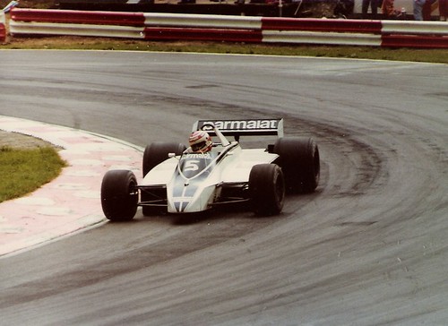
Carlos wrote:Belatti . My favorites are the Alfa at the top and the Brabham, second from the bottom ... all those cars are attractive though.

Reading through the thread gives me a few ideas,why not a one piece/ beam axle built as an extremely light space frame (of small diameter steel) located by anti dive radius arms (google mid sixties GP cars, rear suspension, radius arms) and a Watts linkage, another idea would be a de Dion layout using a light composite axle tube. Maybe ideas worth development. I remember the Caldwell CANAM
Gr7 car as an example.

I would be interested in more info on those cars Carlos. Do you have any links in your vast vault of bookmarks?

Carlos
Carlos
11
Joined: 02 Sep 2006, 19:43
Location: Canada

Re: I-beam suspension arms.

Post

There's not much detail of the Caldwell D7/8 suspension, available, just references to it's De Dion suspension, which is covered in the 'Suspension Bible' link, take a look at the radius arms of the '4 Bar' arms locating a solid axle, the 'Variable Camber Suspension for Steering', will interest you, at the Nation Master site is another short description of the De Dion, follow the links on the 'Panhard Rod' and 'Watts Linkage'. both used to locate a solid axle, the 1/12 model manual's offer real insight into radius arm rear suspension, those links from the rear uprights tieing into the aluminum monocoque chassis just behind the driver. Theres a lot to learn from models. The second pix of the Lotus 49 site is a good example.

http://www.carbibles.com/suspension_bible.html
http://www.nationmaster.com/encyclopedia/De-Dion-tube
http://www.hobbygrandprix.com/modeling/ ... nuals.html
http://www.ddavid.com/formula1/lotus49.htm

This is just about the most detailed description of the Caldwell D7 DeDion suspension I've ever found (had to dip deep into the database for this)

"The other rear winged car on the grid is the Caldwell D7 Chevrolet, driven by Sam Posey (#1). The car has been manufactured by Ray Caldwell at Autodynamics, normally constructor of Formula Vee singlesitters. Initially the car is built around an aluminium monocoque, but later a second unit will be built around a magnesium monocoque. Engine is a 5.7 V8 Chevrolet of 515 bhp, prepared at Traco. The whole project is financed by Sam Posey, the driver. Together with the Chaparral 2G it is the only all-American car on the grid. Ray Caldwell is the first to apply in international racing the famous Dion suspension. At the rear of the D7 proprietary uprights are connected across the car by a lattice of round- and square-section tubing which forms in effect a beam, through which projects the ZF transmission case, located by radius rods and transversally by a Watts' linkage. The front axle is similar, through simpler in detail, and the steering is by drag links from a Volkswagen box on the scuttle. Unlike the Chaparral the rear wing is linked to the roll bar. Pivoting on chassis-mounted struts, it seems effective in the corners, but in feathered position on the straights it causes an unmanageable instability. So the wing is to be operated by the driver's hand. A second version without wings, the D7C is been tested, but not used in racing."

Ray Caldwell stood among the many designers that created the marvel that was Group 7 Racing in North America.

Which was extracted from this survey of the CANAM series of 1967:

http://www.imca-slotracing.com/CANAM-1967.htm


Interesting that so much information has been archived by model car enthusiasts.

Conceptual
Conceptual
0
Joined: 15 Nov 2007, 03:33

Re: I-beam suspension arms.

Post

Carlos wrote:There's not much detail of the Caldwell D7/8 suspension, available, just references to it's De Dion suspension, which is covered in the 'Suspension Bible' link, take a look at the radius arms of the '4 Bar' arms locating a solid axle, the 'Variable Camber Suspension for Steering', will interest you, at the Nation Master site is another short description of the De Dion, follow the links on the 'Panhard Rod' and 'Watts Linkage'. both used to locate a solid axle, the 1/12 model manual's offer real insight into radius arm rear suspension, those links from the rear uprights tieing into the aluminum monocoque chassis just behind the driver. Theres a lot to learn from models. The second pix of the Lotus 49 site is a good example.

http://www.carbibles.com/suspension_bible.html
http://www.nationmaster.com/encyclopedia/De-Dion-tube
http://www.hobbygrandprix.com/modeling/ ... nuals.html
http://www.ddavid.com/formula1/lotus49.htm

This is just about the most detailed description of the Caldwell D7 DeDion suspension I've ever found (had to dip deep into the database for this)

"The other rear winged car on the grid is the Caldwell D7 Chevrolet, driven by Sam Posey (#1). The car has been manufactured by Ray Caldwell at Autodynamics, normally constructor of Formula Vee singlesitters. Initially the car is built around an aluminium monocoque, but later a second unit will be built around a magnesium monocoque. Engine is a 5.7 V8 Chevrolet of 515 bhp, prepared at Traco. The whole project is financed by Sam Posey, the driver. Together with the Chaparral 2G it is the only all-American car on the grid. Ray Caldwell is the first to apply in international racing the famous Dion suspension. At the rear of the D7 proprietary uprights are connected across the car by a lattice of round- and square-section tubing which forms in effect a beam, through which projects the ZF transmission case, located by radius rods and transversally by a Watts' linkage. The front axle is similar, through simpler in detail, and the steering is by drag links from a Volkswagen box on the scuttle. Unlike the Chaparral the rear wing is linked to the roll bar. Pivoting on chassis-mounted struts, it seems effective in the corners, but in feathered position on the straights it causes an unmanageable instability. So the wing is to be operated by the driver's hand. A second version without wings, the D7C is been tested, but not used in racing."

Ray Caldwell stood among the many designers that created the marvel that was Group 7 Racing in North America.

Which was extracted from this survey of the CANAM series of 1967:

http://www.imca-slotracing.com/CANAM-1967.htm


Interesting that so much information has been archived by model car enthusiasts.
Thank you as always!

riff_raff
riff_raff
132
Joined: 24 Dec 2004, 10:18

Re: I-beam suspension arms.

Post

Conceptual wrote:My question concerns the A arms of the front suspension. I am interested in knowing if it is possible to replace them both with a single, horizontal piece.
Yes, it is possible, but not desirable.

A single, cantilevered or beam axle suspension arm would have to carry loads in bending. To do so, it would have to have lots of material or section thickness at its inboard end, making it heavy. A double A-arm suspension takes the loads out as tension/compression forces in the A-arm tubes. The only concern is making sure the compression-side members have adequate buckling strength. The tension members can be extremely thin and light.

That is why a double wishbone is stiffer and has much less unsprung mass than a beam axle ever could achieve.
"Q: How do you make a small fortune in racing?
A: Start with a large one!"

Conceptual
Conceptual
0
Joined: 15 Nov 2007, 03:33

Re: I-beam suspension arms.

Post

riff_raff wrote:
Conceptual wrote:My question concerns the A arms of the front suspension. I am interested in knowing if it is possible to replace them both with a single, horizontal piece.
Yes, it is possible, but not desirable.

A single, cantilevered or beam axle suspension arm would have to carry loads in bending. To do so, it would have to have lots of material or section thickness at its inboard end, making it heavy. A double A-arm suspension takes the loads out as tension/compression forces in the A-arm tubes. The only concern is making sure the compression-side members have adequate buckling strength. The tension members can be extremely thin and light.

That is why a double wishbone is stiffer and has much less unsprung mass than a beam axle ever could achieve.
The entire point of this thread was to make the "beam" a flexible part of the chassis, thus removing the unsprung weight entirely.

Just imagine the top car on this page with "beam wings" instead of A arms. That is what I invisioned originally.

riff_raff
riff_raff
132
Joined: 24 Dec 2004, 10:18

Re: I-beam suspension arms.

Post

OK. I get your point.

But making the beam axel fixed at the roll center does not reduce the bending loads (and thus stresses) it is subject to. In fact, fixing the beam axel at its mid-span will significantly increase the max stress the beam structure experiences for a given wheel bump travel, versus a beam structure that takes the bending load strains out over the full track width.

And it doesn't eliminate the unsprung suspension mass. Any part of the suspension that moves is unsprung. The flexible beam simply has a variable inertia along its length.

Also, since the tire contact patch is offset from the single suspension beam's neutral axis, you must devise some method of reacting the resulting moment produced at the end of the suspension beam.

And finally, it is not a good idea to have an undampened suspension system. So your single suspension beam must have some sort of dampening device attached to it.

I certainly appreciate your sense of creativity and I don't mean to be negative, but a current F1 suspension is a lot more complex and subtle than it first appears.
"Q: How do you make a small fortune in racing?
A: Start with a large one!"

timbo
timbo
111
Joined: 22 Oct 2007, 10:14

Re: I-beam suspension arms.

Post

I heard that the lower wishbones of Ferrari 412T1 was fixed carbon fiber "spring" of sorts. That apparently didn't work well, as Ferrari drivers called car a "dragster".

Belatti
Belatti
33
Joined: 10 Jul 2007, 21:48
Location: Argentina

Re: I-beam suspension arms.

Post

riff_raff wrote: a current F1 suspension is a lot more complex and subtle than it first appears.
Yup!

Rapidly looking to an F1 A arm you can tell that they are designed to work under traction/compression and not under bending. They seem to be elipitcal, orientated in a way wich W is minimus (Tension=M/W) but aero interference is also minimum

Image
"You need great passion, because everything you do with great pleasure, you do well." -Juan Manuel Fangio

"I have no idols. I admire work, dedication and competence." -Ayrton Senna

Conceptual
Conceptual
0
Joined: 15 Nov 2007, 03:33

Re: I-beam suspension arms.

Post

riff_raff wrote:OK. I get your point.

But making the beam axel fixed at the roll center does not reduce the bending loads (and thus stresses) it is subject to. In fact, fixing the beam axel at its mid-span will significantly increase the max stress the beam structure experiences for a given wheel bump travel, versus a beam structure that takes the bending load strains out over the full track width.

And it doesn't eliminate the unsprung suspension mass. Any part of the suspension that moves is unsprung. The flexible beam simply has a variable inertia along its length.

Also, since the tire contact patch is offset from the single suspension beam's neutral axis, you must devise some method of reacting the resulting moment produced at the end of the suspension beam.

And finally, it is not a good idea to have an undampened suspension system. So your single suspension beam must have some sort of dampening device attached to it.

I certainly appreciate your sense of creativity and I don't mean to be negative, but a current F1 suspension is a lot more complex and subtle than it first appears.
Riff,

This beam wing was to be coupled with the in-rim suspension system shown on page 1.

I had thought of the flex along the length, and thought a torsion bar, similar to what is in a guitar neck, could be used to adjust it.

But the largest part of this is it would almost have to be hydraulic drive, since in-wheel suspension doesnt work well with brake discs/calipers!

Thanks for putting some serious thought into my concept, I truly appreciate an educated assessment that allows me to refine what I have conceived.

Once again, thank you! And what do you think the "truss-rod" would bring to such a setup?

xpensive
xpensive
214
Joined: 22 Nov 2008, 18:06
Location: Somewhere in Scandinavia

Re: I-beam suspension arms.

Post

For timbo:
Not sure if this is what you are refering to, but John Barnard played with flexible "knife-edge" joints, rather than the conventional ball-joints, between the suspention arms and the chassis. But I believe these were made from Titanium.

As I can recall, the general idea was to limit the friction in the joints, while the deflection of the metal involved was small enough not to give any fatigue problems anyway.

Patrick Head claimed this solution was breaking the rules in "black and white"
somehow, while Jean Alesi didn't like it for God knows what reason.
"I spent most of my money on wine and women...I wasted the rest"

timbo
timbo
111
Joined: 22 Oct 2007, 10:14

Re: I-beam suspension arms.

Post

xpensive wrote:For timbo:
Not sure if this is what you are refering to, but John Barnard played with flexible "knife-edge" joints, rather than the conventional ball-joints, between the suspention arms and the chassis. But I believe these were made from Titanium.

As I can recall, the general idea was to limit the friction in the joints, while the deflection of the metal involved was small enough not to give any fatigue problems anyway.

Patrick Head claimed this solution was breaking the rules in "black and white"
somehow, while Jean Alesi didn't like it for God knows what reason.
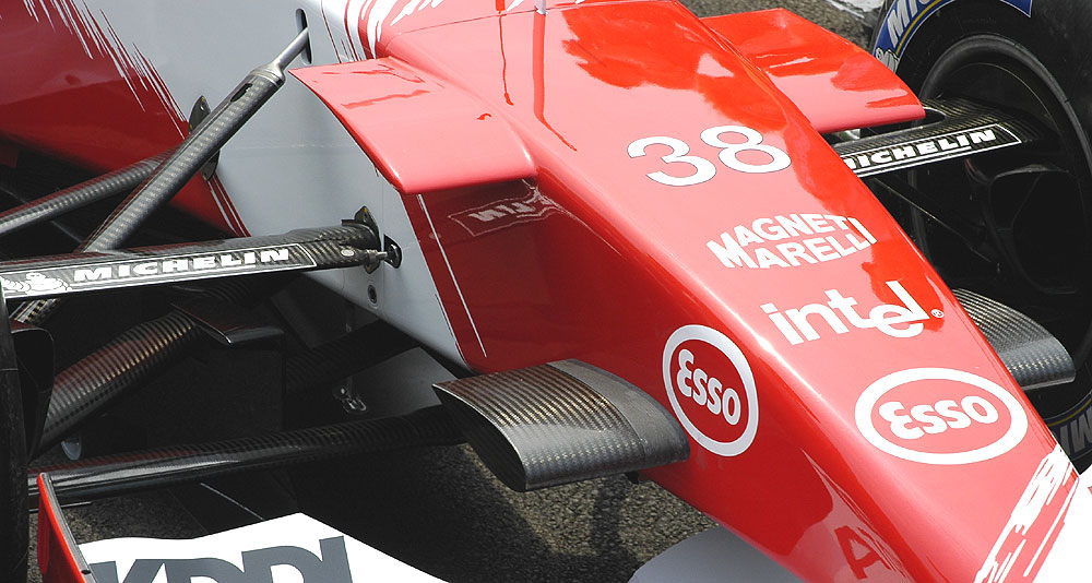
Interesting, right now all teams use flextures to attach suspension arms to the chassis. So if we are talking about the same car, they probably didn't work things right. Or, maybe, suspension was softer those days?

xpensive
xpensive
214
Joined: 22 Nov 2008, 18:06
Location: Somewhere in Scandinavia

Re: I-beam suspension arms.

Post

Well, if everybody in F1 are using flexible suspension joints today, which I in all honesty didn't know, we can add this to John Barnard's outstanding list of technology firsts, such as the carbon-fibre monocoque and finger-tip gear change.
"I spent most of my money on wine and women...I wasted the rest"

timbo
timbo
111
Joined: 22 Oct 2007, 10:14

Re: I-beam suspension arms.

Post

For sure! He always had great concepts in mind, however, he often been to busy to fine-tune and develop them...

On flextures this was discussed several times on this forum. Do a search, and look here http://www.scarbsf1.com/wishbones.html