2 stroke thread (with occasional F1 relevance!)

All that has to do with the power train, gearbox, clutch, fuels and lubricants, etc. Generally the mechanical side of Formula One.
manolis
manolis
107
Joined: 18 Mar 2014, 10:00

Re: 2 stroke thread (with occasional F1 relevance!)

Post

Hello J.A.W.

Talking for 2-strokes and scavenging etc, here is the PatTwo harmonic engine:

Image

( more at http://www.pattakon.com/pattakonPatTwo.htm )

At idling the dark throttle (that with the yellow lever) at the middle of the cylinder is wide open (and the engine runs with almost atmospheric pressure underneath the pistons).
No other throttle is required.
With the dark throttle open, it is like having a 2-stroke with an extremely large crankcase volume (tiny “crankcase” compression).
This minimizes the pumping loss.

When the throttle is completely closed, they are formed two isolated spaces underneath the two pistons. At medium revs the engine makes a lot of torque and power. It is like having a 2-stroke with quite small crankcase volume (high “crankcase compression”).


Question:
In case of tuned exhaust, is the peak power achieved with open or with closed throttle?

Think what this could mean: wide open throttle valve for idling and wide open throttle valve for peak power at high revs!

Thanks
Manolis Pattakos

manolis
manolis
107
Joined: 18 Mar 2014, 10:00

Re: 2 stroke thread (with occasional F1 relevance!)

Post

Hello all.

For top specific power, a sport motorcycle engine needs to operate reliably at extreme revs; it also needs extremely oversquare design; it also needs big diameter valves, high valve lifts and aggressive valve lift profiles.


Did you ever think how the acceleration and the inertia loads in the valve train compare with those of the piston?


Quote from the HMEM forum regarding the differences between the loads in the valve train of a high revving rotary valve engine and of a high revving conventional poppet valve engine:

“As regards the inertia loads, comparing the PatRoVa rotary valve with the poppet valve is like comparing the day with the night.

As a piston, the poppet valve accelerates and decelerates in synchronization with the crankshaft.

During, say, 240 crank degrees the poppet valve opens and closes (frequency: 1.5 of the crankshaft frequency).
Its restoring spring has to be strong enough to accelerate the poppet valve to close following the ramp of the camshaft.

In the Ducati Panigale 1299, the intake valve lift is 16mm for a piston stroke of 60.8mm. This means that the acceleration of the valve is (1.5^2)*(16/60.8 ) =0.59 or 59% of the acceleration of the piston.

Image

Note: the opening and the closing of the valve is far from being pure sinusoidal;
the acceleration of the piston, due to the limited length of the connecting rod, is not sinusoidal , too.
But in the lump sum the acceleration of the valve is more than half of the acceleration of the piston.

With the intake valve weighing 46.8gr (Ducati Panigalw 1299), the overall reciprocating “valve mass” is about 100gr (it is the valve mass plus half of the spring mass, plus a part of the mass of any linkage like, say, the cam follower).

At 11,500rpm the acceleration of the piston of the Panigale is about 5,600g; according the previous, the acceleration of the inlet poppet valve of the Panigale is more than 2,800g.

This means that the spring has to be capable to apply a restoring force of at least 280Kp (about 600lb) to the valve (actually more, for safety), otherwise the valve cannot follow the cam lobe. This means that the camlobe has to apply to the valve / valve spring an even stronger force (necessary for the acceleration of the valve / valve spring and for the compression of the valve spring) in order the valve to move as it moves.

For the motion of the conventional poppet valves they are required extreme forces (which means stress on the parts involved (including the timing chain or belt), friction, wear, cost etc.)
Ducati solved partially the problem by eliminating the restoring valve springs (Desmodromic cylinder heads: the valves not only open positively – as in the conventional valve trains – but they also close positively, without the need of restoring springs).”

End of Quote.


Interesting?


Quote from the same discussion about the time required for the combustion in a model (RC) PatRoVa rotary valve engine:


” The Ducati Panigale 1299 has 116mm bore, 60.8mm stroke and runs reliably till 11,500rpm of the rev limiter.

In the 24.8mm bore x 13mm stroke (6.28cc) PatRoVa model engine (same bore to stroke ratio with the Ducati):

Image

Image

Image

the flame has to travel a 116/24.8=4.7 times smaller distance.

Provided the flame front propagates at the same rate (speed) in the Panigale 1299 and in the PatRoVa model engine, the second burns the mixture until at least 11,500*4.7=53,800rpm

Actually, the flame in the Ducati Panigale extends slower than the flame in the PatRoVa model engine because the shape of the combustion chamber of the first is not good: it is a thin disk (116mm diameter, 5.24 mm average height for 12.6:1 compression ratio), with deep valve pockets on the piston crown and necessarily abnormal shape of combustion chamber walls.
In the one case the flame extends at the two only dimensions (thin disk), while in the second case, wherein almost all the mixture is concentrated into the chamber formed between the two disks of the rotary valve (the clearance between the flat piston crown and the cylinder head is quite small: the limitation is to avoid the piston-cylinder head collision at high revs), the flame extends in three dimensions and proceeds faster with lower thermal loss.

So, as regards the combustion, 50,000rpm is OK for the (above) oversquare PatRoVa model engine.”

End of Quote.


Objections?

Thanks
Manolis Pattakos

User avatar
rscsr
51
Joined: 19 Feb 2012, 13:02
Location: Austria

Re: 2 stroke thread (with occasional F1 relevance!)

Post

Ok you get rid of the "high" forces of the valve return springs. But how much power do you think you will save, by getting rid of it?

gruntguru
gruntguru
563
Joined: 21 Feb 2009, 07:43

Re: 2 stroke thread (with occasional F1 relevance!)

Post

I don't think saving power is the object. More to do with:
- simplification
- reliability
- rapid port open/close
- weight saving
- volume saving
- combustion efficiency (compact chamber)
- no rpm limit
. . . etc
je suis charlie

manolis
manolis
107
Joined: 18 Mar 2014, 10:00

Re: 2 stroke thread (with occasional F1 relevance!)

Post

Hello Rscsr.

You write:
“Ok you get rid of the "high" forces of the valve return springs.”


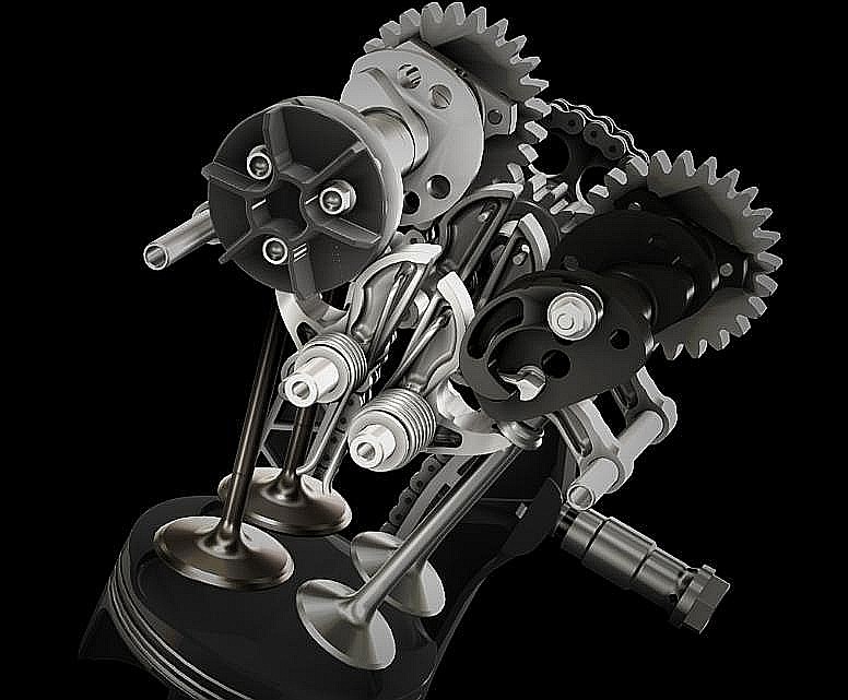
Considering the valve train “linkage”, the forces are not just “high”, they are extreme.

In comparison, the other linkage of the engine (crankshaft – connecting rod – piston – cylinder liner) seems ideal for receiving extreme loads (surface “contact” instead of line “contact”, thick lubricant film etc).


You also write:
“But how much power do you think you will save, by getting rid of it?”


If another motorcycle maker decides to make a replica of the Ducati Panigale keeping all the rest except the Desmodromic cylinder heads which are replaced by conventional cylinder heads with restoring springs for the closing of the valves, keeping the original valve lift profile, things get more than tough.

Just imagine a valve spring providing 280+Kp (600+lb) restoring force and 16mm lift (valve “stroke”).

For ordinary car engines a 28Kp restoring force (i.e. 1/10 of the above) is too much (friction, wear, etc).


Back to Ducati Panigale:

Consider the case Ducati needs / decides to upgrade the Panigale 1299 in order to get substantially more power at substantially higher revs.

The mean piston speed is already too high to increase.

So, what is the reasonable approach?

To further increase the bore and decrease accordingly the stroke; for instance, the diameter increases at 128mm and the stroke decreases at 50mm to keep the cylinder capacity unchanged.

Keeping the same mean piston speed, the present 11,500rpm rev limit goes to 11,500*60.8/50.0= 14,000rpm.

The next requirement for more power is the increased flow capacity of the short (50mm) stroke engine. The valves need to increase in size. Reasonably, the valve diameter increase proportionally with the bore, so the intake valve goes from 46.8mm to 46.8*128/116=51.5mm and the intake valve lift goes from 16mm to 17.7mm.

Compare the increase of the piston acceleration with the increase of the intake valve acceleration:

The piston acceleration increases by 22% ( (50.0/60.8 ) * (14,000/11,000)^2 )

The intake valve acceleration increases by 64% ( (17.7/16.0) * (14,000/11,500)^2 )
And considering the increased mass of the bigger valve, the required force for the motion of the valve is 100% more than in the original intake valve in the normal Panigale 1299.
I.e. the 280Kp (600lb) restoring force becomes now 560Kp (1200lb), otherwise the short stroke (50mm) Panigale 1299 cannot operate at 14,000rpm.


Imagine a valve spring applying 560Kp (5,600Nt) restoring force at a 17.7 “stroke”. In a first approach, the energy required to compress this spring is 5,600Nt * 0,0177m = 99 Joules, and at 14,000rpm (i.e. 7,000rpm of the camshafts) it means 99J * 7,000/60 = 11,5kW of power.
Say, half of this is returned to the kinematic mechanism.
There are 8 valves in total (the exhaust valves have shorter valve lift but they are heavier).
The required power for the two cylinder heads at 14,000rpm is: 11.5kW * 0.5 * 8 = 45kW = 63PS

Isn’t it hard to believe?

And all this lost power (45kW) heats the lubricant and the engine.


Now, consider the same 128mm bore x 50mm stroke Ducati Panigale, this time with PatRoVa cylinder heads.

Image

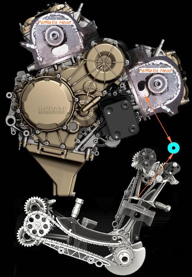
Revving the PatRoVa rotary valves at “only” 7,000rpm (i.e. 14,000rpm of the crankshaft) is more than easy (there are no reciprocating parts; only a balanced “wheel” is spinning at constant angular speed) and requires several dozens of times fewer power just to keep it spinning .

Considering proportional increase of the power with the revs, the 205PS (at 10,500rpm) of the original Ducati Panigale 1299 will go to 250PS (at 12,800rpm) of the short stroke (50mm) PatRoVa Panigale.

However, it is not yet calculated the power loss in the Desmodromic Valve Train of the original Panigale 1299.

Applying the above calculations at only10,500rpm wherein the original Panigale makes its peak power (205PS), the power loss in the Ducati valve train is some 25kW (35PS).

Adding this power (which is not lost in the case of the PatRoVa Panigale 1299) to the above calculated 250Ps, the peak power goes to 285PS at 12,800rpm (only 21.3m/sec mean piston speed). It is a 40% increase relative to the original Panigale 1299.

Worth to mention: at 12,800rpm, the piston acceleration of the above PatRoVa Panigale 1299 equals to the piston acceleration of the original Panigale at 11,500rpm (wherein it still operates reliably) ( 60.8 * 11,500^2 = 50.0 * 12,800^2 )

The top Ducati Panigale model (Superleggera, single compression ring, titanium exhaust valves, same piston stroke with the 1299, 112mm bore) makes its peak power at 11,500rpm and has the rev limit at 12,500rpm (25.3m/sec mean piston speed).

The PatRoVa Panigale at 13,800rpm (only 23m/sec mean piston speed, same piston acceleration with the Superleggera at 12.500rpm) ) can, properly tuned, make:
285PS * 13,800 / 12,800 = 307PS at 13,800rpm.

This is a 50% increase as compared to the original Panigale 1299.

The above are only a theoretical approach.

Objections?

Thanks
Manolis Pattakos

tok-tokkie
tok-tokkie
36
Joined: 08 Jun 2009, 16:21
Location: Cape Town

Re: 2 stroke thread (with occasional F1 relevance!)

Post

The PatRoVa cylinder heads that you have shown are for independent cylinders as in single cyl, V or rotary engines. When we come to the much more common in line engines = straight 4 or 6, parallel twins and V engines of 4 or more cylinders there is a great difficulty fitting in the spark plug and the inlet port with PatRoVa. I am curious about changing the rotary valve to be cross flow so one side is the inlet port and the other side is the exhaust port. I am aware that overlapping port timing will result in fresh combustion mixture going straight out the exhaust so that rules overlapping ports out of consideration.
What are your thoughts about inline engines and PatRoVa?

manolis
manolis
107
Joined: 18 Mar 2014, 10:00

Re: 2 stroke thread (with occasional F1 relevance!)

Post

Hello Tok-Tokkie

You write:
“The PatRoVa cylinder heads that you have shown are for independent cylinders as in single cyl, V or rotary engines. When we come to the much more common in line engines = straight 4 or 6, parallel twins and V engines of 4 or more cylinders there is a great difficulty fitting in the spark plug and the inlet port with PatRoVa. I am curious about changing the rotary valve to be cross flow so one side is the inlet port and the other side is the exhaust port. I am aware that overlapping port timing will result in fresh combustion mixture going straight out the exhaust so that rules overlapping ports out of consideration.
What are your thoughts about inline engines and PatRoVa?”

Here is a V-6 PatRoVa (90 degrees Vee):

Image

It is shown stereoscopically (more on how to look at it: http://www.pattakon.com/pattakonStereoscopy.htm )

The inlet ports are inside the Vee. The exhaust ports are at the external sides of the Vee. Each cylinder has a big inlet port.
On each bank there are four exhaust ports (for the three cylinders). The two middle are shared among the neighboring cylinders. The 240 crank degrees phase difference from cylinder to cylinder enables the exhaust port sharing.

I can’t see any difficulty with the arrangement of the spark plugs or of the ports.

The bore to stroke ratio is high for extreme revs (as explained in the previous post).


If you take the one only bank of cylinders, you have an in-line three.


Here is an in-line-four with plane crankshaft (the typical I-4):

Image

It is substantially less ovesquare than the V-6.

If you look at the five exhaust ports on the exhaust side of the cylinder head, the second and the fourth have a separator blade inside.
This way, each cylinder uses 1,5 exhaust port (the two middle cylinders are spaced 360 degrees from each other, so the common exhaust port (the central exhaust port) is dedicated to the second cylinder every other turn of the crankshaft; the rest time it is dedicated to the third cylinder.


See how the four rotary valves are arranged and driven:

There is a common spline shaft along all cylinders (parallel to the crankshaft).
There are some small roller bearings by which the spline shaft is rotatably mounted onto the cylinder head.
In practice, these small roller bearings operate unloaded.
Only at the sprocket (or timing belt) side of the engine they are used a couple more such roller bearings to take the loads resulting from the tension of the timing belt or chain.

This is important:

Each rotary valve (there are four of them) is free on the spline shaft. It is not a tight connection: there is an adequate clearance that allows the “play” of the rotary valve. This way the valve seats properly on the head and aligns its disks with the combustion chamber ports (or windows) covering/sealing them, and uncovering them.
No matter how long the engine is, each rotary valve will find its perfect position.

So, the PatRoVa rotary valves are substantially free on the cylinder head.
Their freedom enable them to move independently from each other (within some limits, of course) and micro-align each one with its own cylinder head windows.


By the way, for extreme revs the high inertia torque of the plane crankshaft is a limitation.
Other 4-in-line arrangements (cross-plane crankshaft) allow the removal of the “blade separators from the exhaust ports so that each cylinder uses two complete exhaust ports without affecting its neighbor cylinders. But this is another discussion.


According the previous, instead of the “great difficulties” in applying the PatRoVa on multicylinder engines, what I see is more freedom, more opportunities, more variance and way more power and economy.

Thanks
Manolis Pattakos

Brian Coat
Brian Coat
99
Joined: 16 Jun 2012, 18:42

Re: 2 stroke thread (with occasional F1 relevance!)

Post

Manolis: Your calculation of valvetrain power losses in a poppet valve engine with a spring is incorrect due to some incorrect assumptions.

"Imagine a valve spring applying 560Kp (5,600Nt) restoring force at a 17.7 “stroke”. In a first approach, the energy required to compress this spring is 5,600Nt * 0,0177m = 99 Joules, and at 14,000rpm (i.e. 7,000rpm of the camshafts) it means 99J * 7,000/60 = 11,5kW of power."

Two which jump out: 1. Only 50% of the torque input will be recovered - actually, all you lose is the friction. 2. You assume the spring is the dominant friction factor at peak power speed. This is not far from the speed limit of the valvetrain, where the spring/cam contact force is zero. This is why net valvetrain drive torque usually falls with speed.

manolis
manolis
107
Joined: 18 Mar 2014, 10:00

Re: 2 stroke thread (with occasional F1 relevance!)

Post

Hello all.

Quote from the last but one post of mine:

“Applying the above calculations at only10,500rpm wherein the original Panigale makes its peak power (205PS), the power loss in the Ducati valve train is some 25kW (35PS).”


In the calculation the energy recovery was taken zero.
Even if half of the energy provided to the valve train is recovered (it returns to the crankshaft), the remaining friction (12KW) is still too high.

In comparison, the friction in the main bearings of the crankshaft and in the two crankpins is several times lower.

With a mean force of, say, 2 tons (20,000N) per crankpin and 1 ton (10,000N) per crankshaft main bearing), with a friction coefficient equal to 0.001 (plain bearings, hydrodynamic lubrication), and with 50mm and 45mm diameters for the main crankshaft journals and for the crankpins respectively, the friction loss on the crankshaft at the 10,500rpm of the peak power is calculated at:

( 20,000N * 0.001 * pi * 2* 0.045m + 10,000N * 0.001 * pi * 2 * 0.05m ) * 10,500/60 = 1,5kW

This is only one eighth (1/8) of the friction in the Desmodromic valve train.


Flow restrictions and thermal load distribution:

In the following photo from the CycleWorld magazine I marked by circles / ellipses some restrictions of the flow in the Desmodromic Ducati Panigale 1299 (one of the most technologically advanced engines today):

Image

The intake valves at a part of their periphery (green circles) are so close to the cylinder liner that the intake gas flow is substantially restricted.

At their neighboring area (cyan ellipse), the one intake valve becomes an obstacle for the gas entering through the other intake valve, and vice versa.

The exhaust valves at a part of their periphery (red circles) are so close to the cylinder liner that the flow is substantially restricted.

During overlap, the close neighboring of intake and exhaust valves (yellow ellipses) causes the short-circuiting of intake and exhaust spoiling the scavenge of the combustion chamber and allowing in a part of the incoming through the intake valves charge to escape to the exhaust.


Due to the heavily asymmetrical thermal loading on the cylinder head of the Panigale 1299, all but one cooling liquid holes are arranged at the exhaust valve side (see the photo).

Thanks
Manolis Pattakos

User avatar
henry
324
Joined: 23 Feb 2004, 20:49
Location: England

Re: 2 stroke thread (with occasional F1 relevance!)

Post

Manolis:

As I understand it a key requirement of your rotary valve is to maintain a very small clearance between the faces of the valve and cylinder head. Looking at your models there are large variations in the thicknesses of the material of the mating faces with abrupt transitions from thin to thick.

How easy do you think it will be to maintain the flatness of these surfaces given residual stresses from manufacturing and differential heating around the valve?
Fortune favours the prepared; she has no favourites and takes no sides.
Truth is confirmed by inspection and delay; falsehood by haste and uncertainty : Tacitus

manolis
manolis
107
Joined: 18 Mar 2014, 10:00

Re: 2 stroke thread (with occasional F1 relevance!)

Post

Hello Brian Coat

You write:
“Manolis: Your calculation of valvetrain power losses in a poppet valve engine with a spring is incorrect due to some incorrect assumptions.
"Imagine a valve spring applying 560Kp (5,600Nt) restoring force at a 17.7 “stroke”. In a first approach, the energy required to compress this spring is 5,600Nt * 0,0177m = 99 Joules, and at 14,000rpm (i.e. 7,000rpm of the camshafts) it means 99J * 7,000/60 = 11,5kW of power."
Two which jump out: 1. Only 50% of the torque input will be recovered - actually, all you lose is the friction. 2. You assume the spring is the dominant friction factor at peak power speed. This is not far from the speed limit of the valvetrain, where the spring/cam contact force is zero. This is why net valvetrain drive torque usually falls with speed.”


In the analysis regarding the friction consumed into the valve train, the valve spring is not regarded as the dominant friction factor.
On the contrary, the valve spring is taken as an ideal spring wherein the energy required for its compression is fully recovered (is taken back) during its expansion.

What the valve spring does is to provide the required restoring force during the closing of the valve.
But in order to do so, somebody has to compress the spring during the opening of the valve.
The required restoring force from the spring has to be at least equal to the inertia force resulting from the motion of the valve and its kinematic mechanism.
Having the required force and the distance it “travels” (i.e. the lift of the valve) it is calculated the required energy for the opening of the valve. This energy comes from the crankshaft which rotates, through a timing belt or a chain or a set of gearwheels, the camshaft.
The friction is created in the various surfaces that thrust over each other.
During the restoring motion of the valve, a part of the energy already provided by the crankshaft for the opening of the valve is recovered. How much? It depends on the specific kinematic mechanism. But 50% is much according several internet articles / measurements.

So, please be more specific.
What is wrong in my approach /calculations?

Thanks
Manolis Pattakos

Brian Coat
Brian Coat
99
Joined: 16 Jun 2012, 18:42

Re: 2 stroke thread (with occasional F1 relevance!)

Post

Hi

I knew I was going to regret saying anything!

The losses are not a percentage.

They are a result (mainly) of cam/follower friction, caused by a combination of contact force and the prevailing lubrication conditions.

At high speeds, these friction forces *reduce* due to two factors. Reducing contact force over the deceleration portion of the profile (which is much longer than the acceleration part) and improving oil film conditions due to higher entrainment velocities.

manolis
manolis
107
Joined: 18 Mar 2014, 10:00

Re: 2 stroke thread (with occasional F1 relevance!)

Post

Hello Brian Coat.

You write:
“I knew I was going to regret saying anything!”

Having objections (right or wrong, it doesn’t matter) is better than accepting, without really understanding, what the other one claims.

So, do keep on with questions / objections.


You also write:
“At high speeds, these friction forces *reduce* due to two factors. Reducing contact force over the deceleration portion of the profile (which is much longer than the acceleration part) and improving oil film conditions due to higher entrainment velocities.”

On the other hand, think what happens during the valve opening at high revs: the cam lobe has not only to strongly accelerate the valve (and a good part, like 50%, of the valve spring and the rest valve linkage), but it also has to compress the valve spring.

The substantially stronger restoring force when the spring is completely compressed (differently speaking: the valve spring appears substantially "softer" when the valve seats on its valve seat) makes things easier during the initial part of the valve opening; it also makes more possible the bouncing of the valve on its valve seat after the inital closing of the valve.

Thanks
Manolis Pattakos

manolis
manolis
107
Joined: 18 Mar 2014, 10:00

Re: 2 stroke thread (with occasional F1 relevance!)

Post

Hello Henry.

You write:
“As I understand it a key requirement of your rotary valve is to maintain a very small clearance between the faces of the valve and cylinder head. Looking at your models there are large variations in the thicknesses of the material of the mating faces with abrupt transitions from thin to thick.
How easy do you think it will be to maintain the flatness of these surfaces given residual stresses from manufacturing and differential heating around the valve?”

I think these photos help:

Image

Image

In cooperation with the two lips of the combustion chamber ports (or windows), less than half of the “inner” surface of the two disks takes part in the sealing of the high pressure as shows the following animation:

Image

(the same animation in slow motion is at http://www.pattakon.com/PatRoVa/PatRoVa ... g_slow.gif )

The red color on the window lips indicates sealing of a high pressure in the combustion chamber, the orange color is for the medium pressure period and the yellow color on the window lips is for the low pressure difference period.

Around the PatRoVa rotary valve, only the one quarter (about 90 degrees) of the flat surface seals high pressure differences. At this quarter the section of the rotary valve is uniform and its shape gives extreme robustness (as an open wrench; see the photo).

By the way, see for how many degrees the window ports remain completely open. The plot below shows the resulting valve lift profile:

Image


Worth to mention:

The hub (the robust fat and short shaft at the ends of which the two disks are secured) has about uniform temperature.

Only around the exhaust ports of the PatRoVa rotary valve the temperature is substantially higher than the rest valve. But this part of the rotary valve surface is not related with the sealing of significant pressure differences.
So it is not a problem: if necessary, by grinding slightly the flat surface around the exhaust ports periphery, the local thermal expansion cannot cause seizure between the disks and the window lips.


Worth, also, to mention:

In the case of the PatRoVa rotary valve only the one dimension is important for the sealing.

The displacement of the valve at the other two dimensions doesn’t affect the sealing quality.

And, as regards the sealing quality, the significant dimension (in simple words: the distance between the two disks) is small enough to keep the thermal expansion at this direction / dimension low. With the proper materials (like steel or spheroidal graphite iron or even INVAR, i.e. materials having low coefficient of thermal expansion and high modulus of elasticity), and with a DLC coating on the cooperating flat surfaces (for wear-free and friction free operation) the clearance is minimized and the sealing is good.

With the robust hub connecting the two disks, the high pressure affects only slightly the sealing because it causes only a tiny distortion (change of the distance between the two disks).

The recycling during the next suction cycle of any leakage during the high pressure period is another significant characteristic of the PatRoVa architecture.

The eliminated friction loss is another significant characteristic of the PatRoVa architecture.

Thoughts?
Objections?

Thanks
Manolis Pattakos

Brian Coat
Brian Coat
99
Joined: 16 Jun 2012, 18:42

Re: 2 stroke thread (with occasional F1 relevance!)

Post

"On the other hand, think what happens during the valve opening at high revs: the cam lobe has not only to strongly accelerate the valve (and a good part, like 50%, of the valve spring and the rest valve linkage), but it also has to compress the valve spring."

With your calculated 25kW loss @10,500 from the standard Ducati 1299 engine you seem to be implying >2 Bar cam/tappet FMEP. In my experience this is out by one order of magnitude.

This is another attempt to give you a feel for what is going on - my powers of communication are failing me somewhat!

At high revs, most of the valve spring compression is supplied by the valve's own inertia, during the *deceleration* phase, so it does not contribute much to the contact force, which creates the friction. So the friction regime will be mostly hydrodynamic. This is important. Higher speed = lower cam / follower FMEP.

During the valve's *positive* acceleration period at high speed, the acceleration and contact forces are both high of course but the lubrication conduitions are fairly favourable due to the high oil film entrainment velocity, which means the friction regime will be mostly hydrodynamic. Also, this period only comprises about (say) 30/360 cam degrees (assumption: 15 cam degree accel period on opening and closing flanks), this is about 8% of the time, so the positive acceleration period is not dominant, as far as FMEP is concerned.

If you make a simple "kinematics + friction" model using a standard valve acceleration curve (say 5:1 accel ratio), a nominal equivalent mass (say 100g) a sensible spring (say 10% decel cover at redline and a load range within the normal limits), a base circle (say) big enough to give a decent positive radius at peak lift and overlay a standard Stribeck curve ... then you will see what I mean. The results will be incorrect of course because of the simplicity of the assumptions but the effects will be easy to see.
Last edited by Brian Coat on 02 Aug 2016, 11:11, edited 3 times in total.