amouzouris wrote:That is another thought I had, which might also explain why the hole is so tall...If they wanted to just peel off the boundary layer a much shorter hole would have done the job
I probably should have said the inlet reduces mass flow to counter the increase in pressure caused by an adverse pressure gradient. I think that's more illustrative of what's really going on.
Either way, I think the inlet has to be large enough to work at all speeds without choking, and it has to be small enough to avoid drawing in too much air.
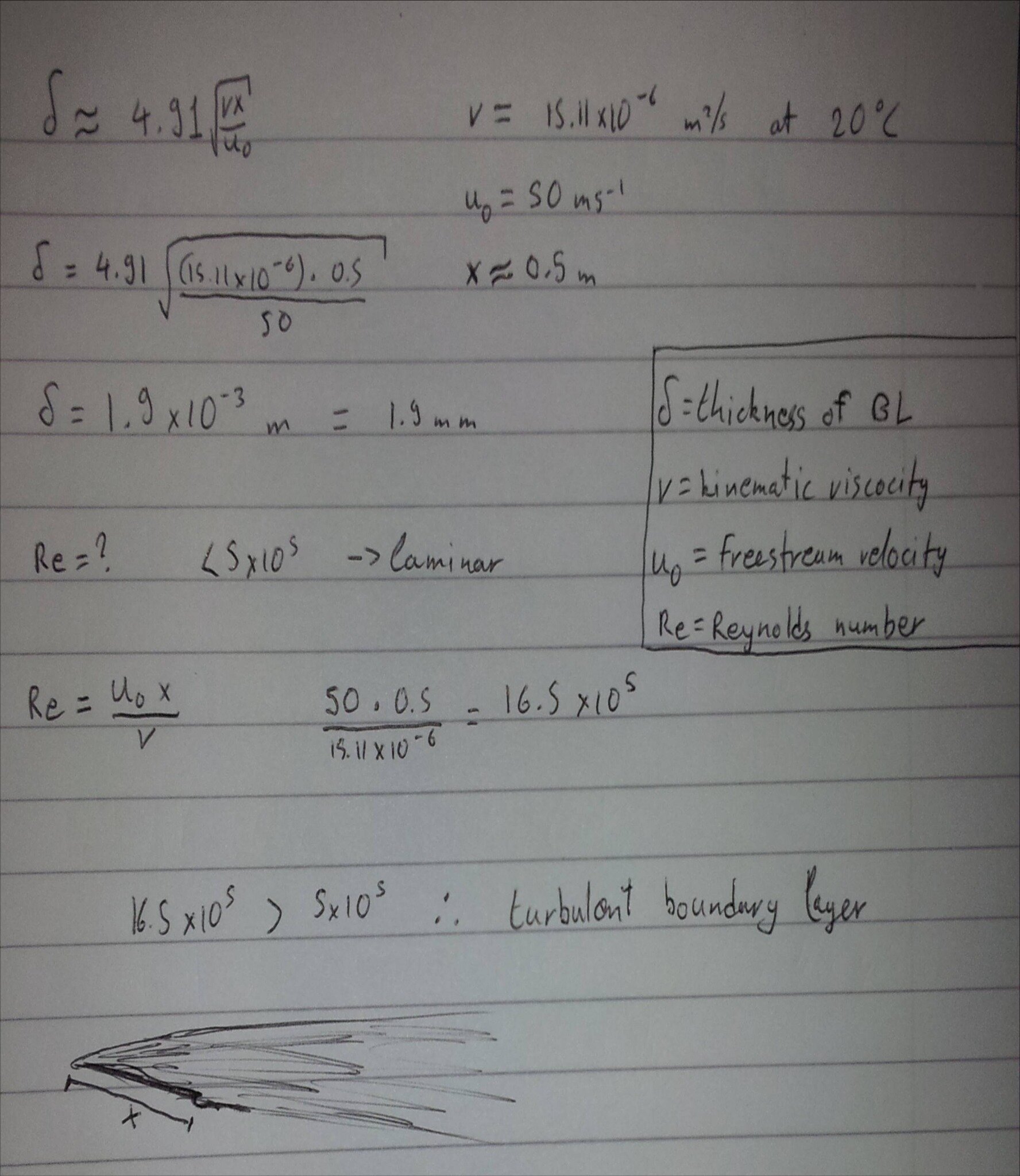
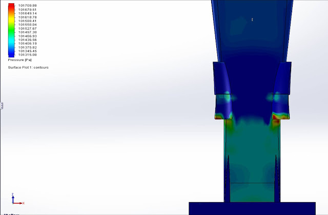
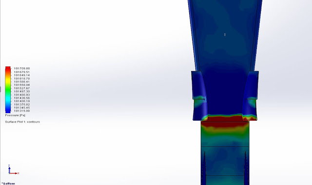
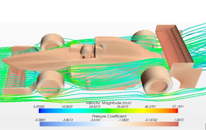
EDIT: Incidentally, you did find an adverse pressure gradient.


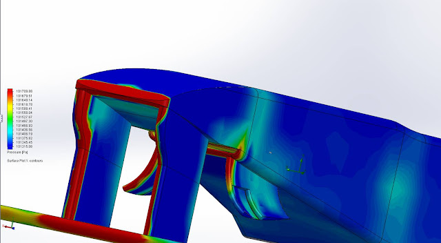
R_Redding wrote:What are the perforated sections in the splitters bow for ?...
[...]
That could be where the system vents. Small ducts oriented in the direction of flow could perhaps energize said flow. (If so, I'm really starting to love the multi-faceted elegance of this system.)
But, then I wonder if those ducts could vent fast enough to keep the system itself from choking.