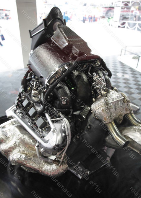
The arrangement of the wastegate valve in this image is very different from the mk1 engine which used two valves, one on either side of the turbine, which widened the PU at that point and was quite likely heavier.

Honda F1 project leader Yusuke Hasegawa has outlined a number of reasons why Honda has been struggling so badly in the beginning of the 2017 Formula One season. He confirmed that lots of problems were not discovered while running on the dynamo meter.


Well, yes. But then If Ferrari, Mercedes and Renault could also have their late season engines at the beginning of the season it would be tougher.godlameroso wrote: ↑05 Oct 2017, 20:01They wouldn't be able to stop me from taking a spanner to it and tearing it apart just to put it back together. I'm grateful for the pictures but sad I can't see in more detail. That they're showing the power unit like this, I imagine it's this engine's last time out.
Honest question, had the engine in the car for this weekend been in the car at the beginning of the season, would there have been more points on the board?
No, it is not. It is clearly behind the cylinder bank.godlameroso wrote: ↑05 Oct 2017, 17:40The turbine is completely shrouded in the Honda engine, that's a very interesting design, probably done to isolate the heat of the turbine from the rest of the engine bay. No wonder they had so many bearing issues, it's certainly impressive they managed to get that working.
1. (Mainly for the benefit of some other posters) HCCI is nothing like diesel. Air and fuel are pre-mixed and ignition happens whenever the temperature of the mix gets high enough for it to ignite (very difficult to control). Ignition occurs simultaneously at many points across the chamber hence the rapid complete burn without knock. (Knock is when the burn progresses across the chamber at the speed of sound.)PlatinumZealot wrote: ↑05 Oct 2017, 18:40Ah yes, I know. It was rhetorical question for Guru. But I want to hear why he thinks the HCCI won't be speed limited. Formula 1 engines have a relatively narrow operating band and the lower edge of that band is so high above any Diesel or HCCI engine has reached.. like 8000 rpms.. I can't see why Honda would shoot them self in the foot by not using the more applicable technology which is TJI.wuzak wrote: ↑05 Oct 2017, 13:41Isn't HCCI compression ignition of a petrol fueled engine? So the timing would largely be like a Diesel.PlatinumZealot wrote: ↑05 Oct 2017, 12:45By how it works combustion is rapid as i have said above, zguru but rapid cobustion is different from the timing of that combustion. TJI will beat it in that regard. How does one time HCCI anyway?
Which restricts how fast the engine can operate in that mode.
My understanding of HCCI engines is that they can convert to spark ignition at high rpm.

So what does happen in a petrol engine if the mixture is not premixed and injection happens into highly compressed hot air as in a diesel engine, does it detonate or can be useful work?gruntguru wrote: ↑06 Oct 2017, 01:42
1. (Mainly for the benefit of some other posters) HCCI is nothing like diesel. Air and fuel are pre-mixed and ignition happens whenever the temperature of the mix gets high enough for it to ignite (very difficult to control). Ignition occurs simultaneously at many points across the chamber hence the rapid complete burn without knock. (Knock is when the burn progresses across the chamber at the speed of sound.)
Detonation only occurs in pre-mixed air/fuel parcels. Injection during combustion does not lead to detonation. Multiple injections prior to ignition still creates pre-mixed parcels which may still detonate.FW17 wrote: ↑06 Oct 2017, 04:53So what does happen in a petrol engine if the mixture is not premixed and injection happens into highly compressed hot air as in a diesel engine, does it detonate or can be useful work?gruntguru wrote: ↑06 Oct 2017, 01:42
1. (Mainly for the benefit of some other posters) HCCI is nothing like diesel. Air and fuel are pre-mixed and ignition happens whenever the temperature of the mix gets high enough for it to ignite (very difficult to control). Ignition occurs simultaneously at many points across the chamber hence the rapid complete burn without knock. (Knock is when the burn progresses across the chamber at the speed of sound.)
Auto ignition of petrol happens between 250 - 280 deg C while diesel is at 210 deg C, cannot the temperature of the charge air inside the cylinder be raised to 280 deg C or higher to promote auto ignition of petrol?
Can't the detonation be controlled by multiple injections like in a Diesel?
I feel like what you are seeing in those photos hardly gives anything away anyway.. not enough to be concerned of prying eyes. Mercedes does a video on every engine they've had each year and safe to say they haven't changed architecture.

I meant there's a very thick heat shield over the turbine.wuzak wrote: ↑06 Oct 2017, 01:32No, it is not. It is clearly behind the cylinder bank.godlameroso wrote: ↑05 Oct 2017, 17:40The turbine is completely shrouded in the Honda engine, that's a very interesting design, probably done to isolate the heat of the turbine from the rest of the engine bay. No wonder they had so many bearing issues, it's certainly impressive they managed to get that working.

Maybe it was in the original regulations? I remember there being some sort of torque limit for the K from 0 up to a certain RPM, 4000 seems right if I remember. Or maybe I've had too many beers since...
That's wrong.F1NAC wrote: ↑05 Oct 2017, 10:42
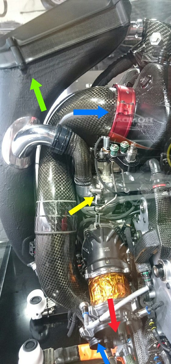
piping from plenum to cylinders, 2 pipes per each bank, red arrow is regulator for wastegate
https://pbs.twimg.com/media/DLW_uJ5VYAEcAWV.jpg:large
As I thought...muramasa wrote: ↑06 Oct 2017, 13:20That's wrong.F1NAC wrote: ↑05 Oct 2017, 10:42
piping from plenum to cylinders, 2 pipes per each bank, red arrow is regulator for wastegate
https://pbs.twimg.com/media/DLW_uJ5VYAEcAWV.jpg:large
There are 3 inlet pipes for each bank.
"4" in that pic goes to 2nd cylinder or middle one on the right
"3" in that pic goes to 3rd cylinder or the right rear
ditto for left bank
There is a 3rd inlet pipe below "3" in that pic
of course this goes to 1st cylinder or right front
ditto for left
Not clear from pics because the thing is black and in the dark/shadow but in person it's easy to distinguish. The pipes are bent quite a bit.
btw MGU-H is directly attached/coupled to the compressor, which is also easy to see in person.
stevesingo wrote: ↑05 Oct 2017, 15:26
My guess is they are the intake runners for cylinders 2,3,5,6, 1&4 being entirely inside the plenum. The runners are not symmetrical. Runner indicated 4 in the picture seems to have the tightest radius and may feed cyl 2, runner 1 is the next tightest radius and i guess that would feed cylinder 5. Runners indicated 2&3 feeding 6&3 respectively due to 3 being slightly further forward.