Under floor flow & diffusers

Here are our CFD links and discussions about aerodynamics, suspension, driver safety and tyres. Please stick to F1 on this forum.
shelly
shelly
136
Joined: 05 May 2009, 12:18

Re: Under floor flow & diffusers

Post

The suction peak at the floor leading edge is caused by the leading edge itself, because it is round. The downforce is increased by the teatray and bargboard vortex system taht cause the 2 blue spikes
twitter: @armchair_aero

User avatar
variante
133
Joined: 09 Apr 2012, 11:36
Location: Monza

Re: Under floor flow & diffusers

Post

Indeed.
The presence of a front wing is vastly negative for undertray's performance.

Still, the better the diffuser, the greater the suction peak upstream, obviously.

MadMatt
MadMatt
125
Joined: 08 Jan 2011, 16:04

Re: Under floor flow & diffusers

Post

shelly wrote:The suction peak at the floor leading edge is caused by the leading edge itself, because it is round. The downforce is increased by the teatray and bargboard vortex system taht cause the 2 blue spikes
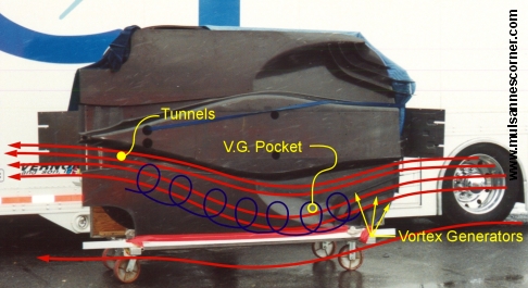
This is not correct. I experienced high pressure at the leading edge of the floor UNDER it sometimes. I would think that rake helps generating the low pressure and that some vortex generating devices are creating this situation. Again, talking about the leading edge of the floor, not the diffuser section.

User avatar
variante
133
Joined: 09 Apr 2012, 11:36
Location: Monza

Re: Under floor flow & diffusers

Post

No, Matt, shelly is right. The rounded leading edge of the floor generates downforce by itself. Its efficiency can be incresed by vortices, rake or by the suction of the diffuser, but it works on its own anyway.

PS:
Image
Maybe it can be seen a little better here.
Its working principle is simple: it's like a venturi channel that produces some drag to accelerate air and create some downforce.
Last edited by variante on 17 Feb 2015, 23:55, edited 1 time in total.

MadMatt
MadMatt
125
Joined: 08 Jan 2011, 16:04

Re: Under floor flow & diffusers

Post

variante wrote:No, Matt, shelly is right. The rounded leading edge of the floor generates downforce by itself. Its efficiency can be incresed by vortices, rake or by the suction of the diffuser, but it works on its own anyway.
Maybe I am wrong, but I will dig pictures of this when I come back home this weekend. I had a design that effectively had a big rounded shape at the leading edge, and the air was getting under it and under the floor yes, but the fillet surface had high pressure under it. I will dig pictures it is easier to explain.

chuckdanny
chuckdanny
69
Joined: 11 Feb 2012, 11:04

Re: Under floor flow & diffusers

Post

shelly wrote:From the CFD thread of this forum, some months ago:
techF1LES wrote:Actual screens from Williams' design office

http://a.yfrog.com/img850/8106/hcjw.png
leading edge suction peak clearly visible, along with vortex low pressure strake at the front (the blue narrow zone protruding from the front).
Also noticeable double diffuser effct and diffuser kink line suction peak
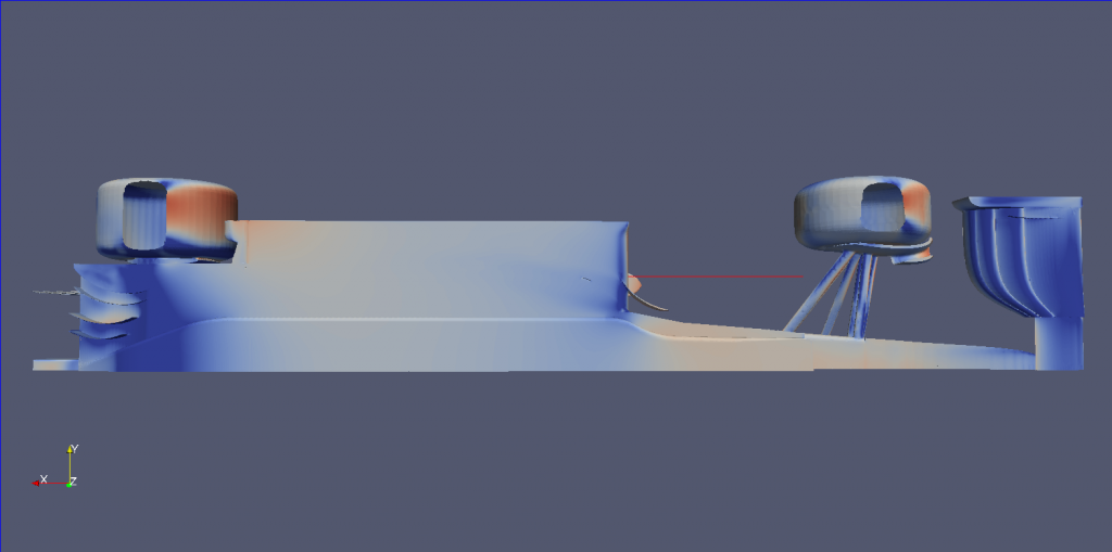
While it's true there are vortices i think the low pressure extension (blue narrow zone protuding) comes from the design of the profile between plank and step plane which is like this
Image

chuckdanny
chuckdanny
69
Joined: 11 Feb 2012, 11:04

Re: Under floor flow & diffusers

Post

The best cfd flowvis i have seen so far
Renault R28
Image

Just_a_fan
Just_a_fan
593
Joined: 31 Jan 2010, 20:37

Re: Under floor flow & diffusers

Post

That clearly shows a strong bargeboard-induced vortex in the place mentioned by Shelly. There is a smaller vortex running along the reference plane edge as suggested by you although it appears to be generated by the t-tray.
If you are more fortunate than others, build a larger table not a taller fence.

chuckdanny
chuckdanny
69
Joined: 11 Feb 2012, 11:04

Re: Under floor flow & diffusers

Post

Yes, but i'm fair, i posted the proof i was wrong !
Though, i don't know if it is the vortex that create additionnal low pressure or it is painted by a low pressure area it is travelling through.

MadMatt
MadMatt
125
Joined: 08 Jan 2011, 16:04

Re: Under floor flow & diffusers

Post

Great pictures guys! I see that there is indeed a strong vortex generated that goes right under the front of the floor as I thought. I will definitely dig CFD shots of what I was saying earlier, maybe I am wrong, I never said I was always right, if I am wrong I hope people tell me so I can improve myself! :)

EDIT: Weird to display the streamlines as pressure, and not speed.
Last edited by MadMatt on 18 Feb 2015, 22:14, edited 1 time in total.

Just_a_fan
Just_a_fan
593
Joined: 31 Jan 2010, 20:37

Re: Under floor flow & diffusers

Post

chuckdanny wrote:Yes, but i'm fair, i posted the proof i was wrong !
Though, i don't know if it is the vortex that create additionnal low pressure or it is painted by a low pressure area it is travelling through.
I've "upped" you for your honesty =D>

I think the vortex creates the region of low pressure by being a tight coil of fast moving, and thus relatively low pressure, air. That's my understanding of it, for what it's worth.
If you are more fortunate than others, build a larger table not a taller fence.

wesley123
wesley123
204
Joined: 23 Feb 2008, 17:55

Re: Under floor flow & diffusers

Post

Since the use of vortices popped up;

Image
The Lola Champcar(and many other single seaters) utilized underbody vortices to generate downforce. I guess quite a large amount of underbody downforce generation comes from the utilization of these vortices?
"Bite my shiny metal ass" - Bender

chuckdanny
chuckdanny
69
Joined: 11 Feb 2012, 11:04

Re: Under floor flow & diffusers

Post

That's what i wanted to express, now i can illustrate.
The presence of the tires create a venturi effect, we can see it on these simple 2d cases with and without rear tires.
Look how it accelerate flow at the front and how it gives thrust back to the stream over the diffuser. Especially with rake the section of rear tires is even bigger hence the throat narrower.
Of course real flow is 3d and downwashing from the upper sidepod area has its effect but hey!it seems correct !

without rear tires :
Image

With rear tires :
Image

The case was at 50m/s, the front tires plus sidepod accelerate the flow up to 106m/s, 70 in average.

chuckdanny
chuckdanny
69
Joined: 11 Feb 2012, 11:04

Re: Under floor flow & diffusers

Post

And now with endplates :

Image

Look how it brings the flow back to a symetrical pattern !

CBeck113
CBeck113
51
Joined: 17 Feb 2013, 19:43

Re: Under floor flow & diffusers

Post

Very nice posts chuckdanny. Just a note: you are showing the air speed along the axis of the car, but that does not directly correlate to the pressure in these areas, because the air is often still traveling at the same speed but with a different vector. Best example of this is the wheel: the air is moved around the front of the wheel and then converges behind it due to the low pressure area there. This air still has the same (or very similar) energy as it had while passing the wheel, so it won't simply decelerate, but fill in the low pressure area. This results in turbulent flow (chaotic pressure changes), which is maintained by creating vortices and/or flow (like endplates in your simulation) to contain this bad air, and keep it from flowing under the car. This is the reason why aerodynamic engineers tend to use pressure and not velocity: much easier to visualize.
“Strange women lying in ponds distributing swords is no basis for a system of government. Supreme executive power derives from a mandate from the masses, not from some farcical aquatic ceremony!” Monty Python and the Holy Grail