[KVRC ~ish] CCE LMP01

Post here information about your own engineering projects, including but not limited to building your own car or designing a virtual car through CAD.
User avatar
machin
162
Joined: 25 Nov 2008, 14:45

Re: [KVRC ~ish] CCE LMP01

Post

I thought I would do a short post on reading NACA data using the performance curve for a single NACA 4415 aerofoil, as presented in NACA report No.460. I'm starting right at the beginning so please don't take offence at any of this: it is aimed at someone with no aerodynamic knowledge at all!

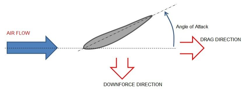
One point to note is that these tests were all conducted from an aeronautical point of view, where the aim was lift, so the aerofoil profile is "upside down" compared to what we need. Just draw it the other way up.

Image

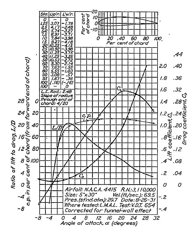
The full report can be found here:- http://naca.central.cranfield.ac.uk/rep ... rt-460.pdf

So, what does it tell you: well you have lines showing CL , CD and L/D based on the angle of Attack of the profile compared to the on-coming air direction.

First of all you need to determine from your model your wing's angle of attack (A.o.A), which is measured as per below:

Image

Then simply read up the chart from your angle of attack until you hit the CL, CD or L/D lines and then read across to the corresponding axis to find out the value for each.

So at 4 degrees A.o.A the CL reads off as approx 0.6, CD as approx 0.03 and L/D as approx 20:1

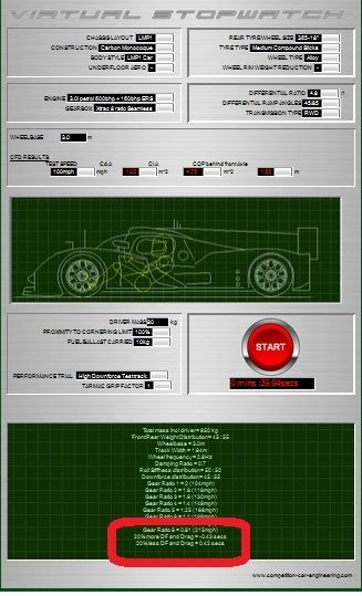
To determine the downforce or drag you must first multiple the CL or CD by the plan area of the wing to obtain CL.A or CD.A.

Then, as posted by AratzH above, to find the actual downfoce or Drag in Newtons you calculate as follows:-

downforce = CL.A x rho(air density) x V^2(velocity squared)

Drag = CD.A x rho(air density) x V^2(velocity squared)

where air density is in kg/m^3 and velocity is in m/s

I normally take air density as 1.22kg/m^3, and 100mph = 44.7m/s as per CAEDevice's post.

So now you can look for other wing profiles and make a selection and determine the your own downforce or drag figures, although, as posted above: the NACA data is for a slender wing without the wing tip vortex effect... so your performance is likely to be slightly worse than predicted...
COMPETITION CAR ENGINEERING -Home of VIRTUAL STOPWATCH

User avatar
machin
162
Joined: 25 Nov 2008, 14:45

Re: [KVRC ~ish] CCE LMP01

Post

OK, so design for the high downforce rounds of KVRC-2015 are now over and we move on to the medium downforce rounds.

The KVRC test track has now been updated to reflect the characteristics of the remaining races... which can be accessed here:- (Note the engine power has been reduced to promote a lower downforce set-up).

KVRC Test Track


The next question is.. how do you go about sorting out what set-up is best... the first thing you can do is put in your latest results and see what the data read-out at the bottom tells you:-

Image

This will tell you if more or less downforce (and of course drag) is going to be quicker....

But if you want to get a little more sophisticated you can do similar to what I've done below... essentially you build a chart of Cd.A and Cl.A showing the results you've had to date. To these results I've added a fourth point estimating the results if I had no downforce or lift. Hopefully this will follow a reasonable curve... all the points along that curve are what you could reasonably expect to achieve if you altered your wing angles but kept your basic design unchanged...

For each of those points you can then run the KVRCtest track and see what lap times you get. I've shown these graphically by adding a vertical bar to each point (taller bar = slower). This tells me which area of Cl.A and Cd.A for my car will yield me the best result...

Image

Once you have the optimum set-up from your existing models you can then start refining... you're either going to want more downforce for the same drag, or less drag for the same downforce (or more downforce and less drag).

It might also be interesting to try some of your opponents Cd.A and Cl.A figures in the KVRC test track to see if their designs are going to yield a better result.. but bear in mind that even if you try and copy their car exactly you might get completely different aero coefficients if the details are not exactly the same....
Last edited by machin on 25 Jul 2015, 14:01, edited 1 time in total.
COMPETITION CAR ENGINEERING -Home of VIRTUAL STOPWATCH

User avatar
CAEdevice
48
Joined: 09 Jan 2014, 15:33
Location: Erba, Italy

Re: [KVRC ~ish] CCE LMP01

Post

Thanks a lot! Very interesting explanation of the setup method.

User avatar
machin
162
Joined: 25 Nov 2008, 14:45

Re: [KVRC ~ish] CCE LMP01

Post

Now that the test round is over we have a load more information to go on with which to design a car for the lower downforce rounds to come...

The first thing I wanted to do was understand the scope for what is possible within the restrictions of the KVRC rules, and the best way to understand that is to see what people have actually managed to achieve.

At the lower end of the downforce spectrum It is clear that a car having no downforce would still generate drag, likely to be in the region of Cd.A = 0.45 to 0.5; this represents our minimum possible drag configuration.

At the other end of the spectrum we know that JJR and Variante produced some really good high downforce designs that would be difficult to improve upon, so this represents the upper limit of what is practically possible: a Cl.A of 8 with a minimum Cd.A of about 1.8.

Estimating what is possible between these two points is difficult, but likely to follow an exponential curve: i.e. at first gains in downforce are relatively "easy" (i.e. little gain in drag for a big gain in downforce), then getting harder until we reach our upper limit.

This allow us to draw a region on our Cl.A vs Cd.A chart representing the limits of what is practically possible: The red region is outside the "bounds of practicality".

Image

If we now compare the "lines of equal laptime" to the "bounds of practicality" we see that the best lap time (i.e. furthest away from the lowest lap time line) will be somewhere in the region of Cd.A = 1 and Cl.A = 6, so they are the aero coefficients that I want to aim to achieve....

....Of course if I can achieve those figures then there is no reason not to try and push the "bounds of possibility" even further towards the bottom right-hand corner of the graph, i.e. more downforce for lower drag...
COMPETITION CAR ENGINEERING -Home of VIRTUAL STOPWATCH

User avatar
RicME85
52
Joined: 09 Feb 2012, 13:11
Location: Derby

Re: [KVRC ~ish] CCE LMP01

Post

While I love this thread for its technical insight, I have zero idea how to use the information to produce a decent upgrade to my car.

User avatar
LVDH
45
Joined: 31 Mar 2015, 14:23

Re: [KVRC ~ish] CCE LMP01

Post

This chart is extremely useful.
When designing the car you might have wondered in which direction to go.
In the first races it was quite clear that you need downforce over any increase in drag.

For the last race the decision was a bit more difficult. The track and the ones to come require a car with a good aero efficiency. But what is the right number? L/D = 4, =5, or 6? The chart here suggests it should be around 5.75.
You get your optimal lap time be moving the iso line parallel towards the red curve and also moving that curve in "parallel" towards the lap time iso lines. if you plot a point everywhere where they touch you get that optimal designs you can achieve.
But the curve machin plotted will be different for everyone. You design concept, creativity and CAD skills will create a different curve. In my case I can get close to L/D of 5.

So in short every new design you test should improve L/D towards 5.75 while maintaining CoP at 1.65.

User avatar
CAEdevice
48
Joined: 09 Jan 2014, 15:33
Location: Erba, Italy

Re: [KVRC ~ish] CCE LMP01

Post

I agree with Mantium, the chart is very useful.

It also show that in the last three races, you don't need to completely redesign your car but to work on details to improve efficiency.

Anyway, it would have been interesting to add a "very slow" df track (Indianapolis? Old Monza?).

User avatar
machin
162
Joined: 25 Nov 2008, 14:45

Re: [KVRC ~ish] CCE LMP01

Post

Absolutely: the red area is only a suggestion of what is practically possible within the rules based on what we've seen from all the competitors so far, and not an absolute limit: Someone could come along and introduce a game-changer ("double-diffuser"-style) which pushes the "Bounds of practicality" further towards the lower right hand corner....

It is useful to plot all your own previous results on a chart like this (see sample below):-

Image

...so from that chart you'd conclude that Configuration 3 is the best (fastest), however what it doesn't tell you is which configuration has the biggest scope for improvement (i.e. biggest scope for reduction in drag and increase in downforce)... maybe configuration 3 cannot be improved, whereas configuration 2 has lots of scope for improvement and hence could result in the better lap time with some development? That is something that only the car designer himself can decide...

I guess the best solution for most competitors is as you say Matteo: to stick with what they've got and make incremental improvements? Any design will be faster if you can decrease drag and/or increase downforce....
While I love this thread for its technical insight, I have zero idea how to use the information to produce a decent upgrade to my car.
I think your latest car looks pretty good... maybe these points are worth considering, if you haven't already?
  • Are you using an efficient wing design?
  • Are you using the Variante/JJR diffuser shape?
  • Does your design allow for an "easy" passage of air over and around the car?
  • Have you created any "dead ends" which trap/restrict air flow?
  • Can you reduce the frontal area of any body parts?
  • Are there body parts which can be removed entirely?
  • Can you introduce better streamlining to the body parts?
  • Avoid sharp edges on the front of bodywork.
  • Can you reduce the number/amount of times you "ask" the air to change direction?
(Finally worked out how to use the "list" forum code!)
COMPETITION CAR ENGINEERING -Home of VIRTUAL STOPWATCH

MadMatt
MadMatt
125
Joined: 08 Jan 2011, 16:04

Re: [KVRC ~ish] CCE LMP01

Post

I think machin's advices are very good for those who are wondering how to improve their cars. But please read them 2-3 times and ask yourself if you cannot do better, because for sure you can, it is just a matter of spending some time thinking about it and trying to look at it with an external eye. Food for thoughts there guys. Thanks machin!

User avatar
machin
162
Joined: 25 Nov 2008, 14:45

Re: [KVRC ~ish] CCE LMP01

Post

Thanks Matt; just to add to that: I mentioned in that list above about stream-lining: it is really surprising just how much drag reduction you get by streamlining a shape; its pretty obvious that a flat plate perpendicular to the flow is rubbish aerodynamically, but check out the difference between the circular cylinder and the stream-lined cylinder... so assuming the frontal area is the same the streamlined cylinder has 90% less drag than the circular cylinder!

Image
COMPETITION CAR ENGINEERING -Home of VIRTUAL STOPWATCH

User avatar
machin
162
Joined: 25 Nov 2008, 14:45

Re: [KVRC ~ish] CCE LMP01

Post

But please read them 2-3 times and ask yourself if you cannot do better, because for sure you can, it is just a matter of spending some time thinking about it
That reminds me of a story I heard about the development of the McLaren f1 roadcar; every week Gordan Murray would take one random item off the car, give it to the development team and say "take 10% off the weight of that component".

We could do something similar: each week take a different part and think about how to improve it aerodynamically: more streamlining, smaller frontal area, etc etc.
COMPETITION CAR ENGINEERING -Home of VIRTUAL STOPWATCH

User avatar
RicME85
52
Joined: 09 Feb 2012, 13:11
Location: Derby

Re: [KVRC ~ish] CCE LMP01

Post

machin wrote:
While I love this thread for its technical insight, I have zero idea how to use the information to produce a decent upgrade to my car.
I think your latest car looks pretty good... maybe these points are worth considering, if you haven't already?
  • Are you using an efficient wing design?
  • Are you using the Variante/JJR diffuser shape?
  • Does your design allow for an "easy" passage of air over and around the car?
  • Have you created any "dead ends" which trap/restrict air flow?
  • Can you reduce the frontal area of any body parts?
  • Are there body parts which can be removed entirely?
  • Can you introduce better streamlining to the body parts?
  • Avoid sharp edges on the front of bodywork.
  • Can you reduce the number/amount of times you "ask" the air to change direction?
(Finally worked out how to use the "list" forum code!)
1 - Front wing is designed from Variantes FW from when he had that crazy front end. Chris supplied a cross section and I was able to copy the airfoil from that although its more than likely not the best representation nor the best profile to go with. Rear wing is just the one supplied by Chris with a change of AoA.

2 - Yes, again, the cut aways have helped and I have also studied the front engine model CAE shared.

3 - Its something I have been working on with the side pod solution on the latest car, this time taking inspiration from your model in this thread.

4 - Wheel covers might be the biggest stumbling block here, will see what the open side to the front will do.

5 - The front suspension cover I am hoping will help here although there is probably a trade off: less frontal area but no surface to control the airflow like you would get with a large 'bonnet' style cover

6 - Yeah, the upper crash structure but then the car wouldnt be legal :lol:

7 - Yes but is much improved on previous cars.

8 - This is something I have worked on with each iteration. Early cars had sharp edges and not very well formed corners, this latest car I have taken inspiration from F1 regulations and have use 45R fillets around the sidepod and wheel covers.

9 - Probably although I dont think I have that much going on, not like previous versions which had vanes behind the front wheel cover and in front of the side pod for example.

MadMatt
MadMatt
125
Joined: 08 Jan 2011, 16:04

Re: [KVRC ~ish] CCE LMP01

Post

machin wrote:
But please read them 2-3 times and ask yourself if you cannot do better, because for sure you can, it is just a matter of spending some time thinking about it
That reminds me of a story I heard about the development of the McLaren f1 roadcar; every week Gordan Murray would take one random item off the car, give it to the development team and say "take 10% off the weight of that component".

We could do something similar: each week take a different part and think about how to improve it aerodynamically: more streamlining, smaller frontal area, etc etc.
And that leads to an idea of mine I had for some time which is designing a car with ideas and advices from the forum members. But I think it would take too long. I thought about something like opening a 3 days discussion about 1 area of the car (front wing, fenders, rear view mirrors, etc), and at the end of these 3 days a decision would be made based on what the forum members would say, and I would design that part, and move on to the next.

But the issue is that once you design something, it is never fixed on the car. You would then decide to do X rear wing and it would require to modify the front of the car that you did few weeks ago, so not possible, but that would have been nice to have something like "you decide, I make it, we win" :D

User avatar
machin
162
Joined: 25 Nov 2008, 14:45

Re: [KVRC ~ish] CCE LMP01

Post

RicME85 wrote:
5 - The front suspension cover I am hoping will help here although there is probably a trade off: less frontal area but no surface to control the airflow like you would get with a large 'bonnet' style cover
One thing that I would say is that with aerodynamics the shape should take precedence over the frontal area... See example below: You can fit 10 of the small circular elements stacked one above the other inside the streamlined shape, and yet the streamlined shape has the same drag as one of the small circular elements!

That means i think you would be better off encapsulating all the front suspension in one teardrop as per below:-

Image

Of course the best solution is smaller frontal area and a streamlined shape...

Fundamentally I don't see anything too wrong with your latest car...But some ideas I had which might be worth trying:-

Image

1. As discussed above: reduction of drag coefficient
2. To stop air "tripping" off the exposed inside face of the wheel-well behind the wheel
3. To keep airflow from "tumbling" over the top of the side-pod
4. To avoid the downward slope on the rear wheel fairings which I think will cause lift. Also this allows you to support the rear wing from the end plates, and therefore remove the central supports.
5. Bigger diffuser area and better stream-lining to the rear wheel fairings. (particularly important since I have removed the stream-lining in the vertical plane in suggestion 4.).
COMPETITION CAR ENGINEERING -Home of VIRTUAL STOPWATCH

User avatar
CAEdevice
48
Joined: 09 Jan 2014, 15:33
Location: Erba, Italy

Re: [KVRC ~ish] CCE LMP01

Post

I think that the "lessons" of machin should be collected in booklet for the next year!