Thank you Machin!
I insist (it will be one of my proposal for the KVRC2016): this thread should be collected in a booklet provided to all the team who will participate.
- Login or Register
No account yet? Sign up


OK, I took the time to start looking into this.machin wrote:I always thought the purpose of the open sides was to encourage air through the front end aerodynamics... rather than any attempt at supplying the diffuser, but to be honest one thing I've learnt about aerodynamics is that it is bloody complex!
My thinking was this: air will always take the easiest route around an object (or in scientific-speak: "It follows the pressure gradient"): to ensure that the air goes through the front-end aero (rather than around the sides of the car), you want an unrestricted flow between the wheels and out towards the back of the car, opening up the sides like this (in my thinking) increases the ease with which air can flow through the front end... Essentialy, it has more ways to "get out" once it has been between the front wheels: either over the sidepod, or down the sides....
However, I am intrigued by your finding that it "doesn't work". In terms of aero coefficients, how does it affect the results? Reduction in Cl.A? Increase in Cd.A and/or drastic change in COP (if so, which way; forwards or backwards)?
Cool. I must admit: I like the numbers... but I think you are right: general rules and interpretation of the CFD results is far more useful to the improvement of the car... If we do compile some of this info into a booklet for next year I'll take that into account.The last two pages have cleared a lot of things up for me, the start of the thread was a lot of technical number crunching that went well over my head but now I think I can make some real improvements if I get the time to sit down and assess things properly.
Awesome! The interesting thing for me is that the change (which looks like quite a big difference) doesn't really make a huge difference in reality... I'm guessing that with some refinement both solutions could be made to work equally as well as each other...LVDH wrote:
OK, I took the time to start looking into this.
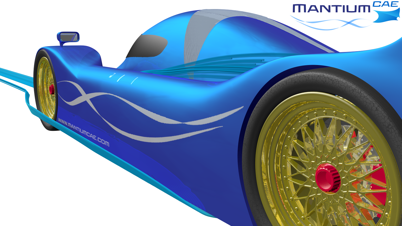
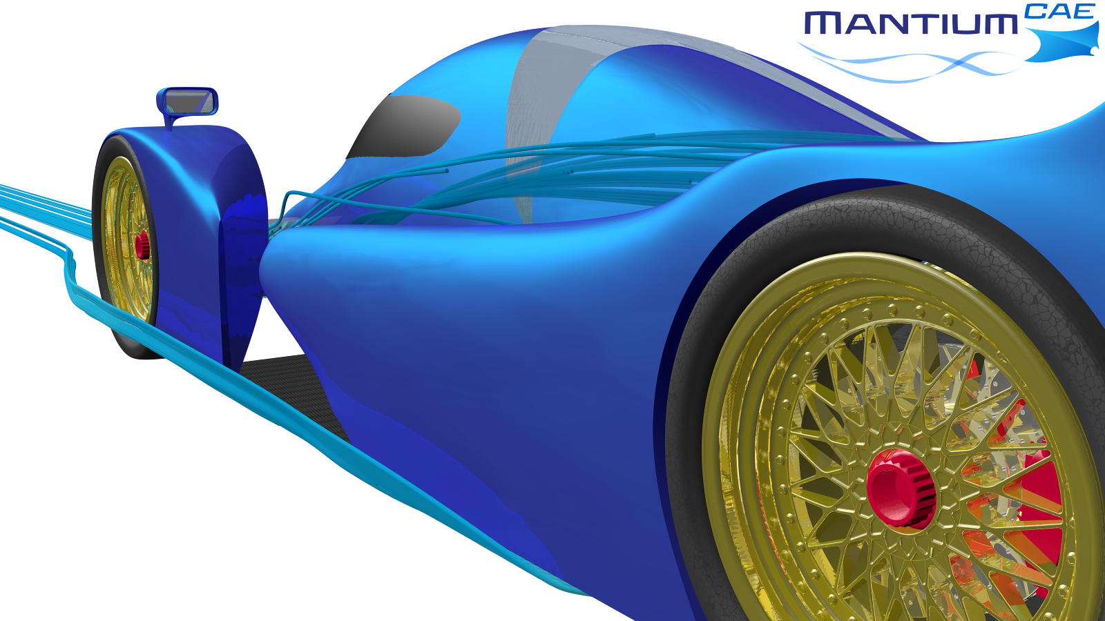
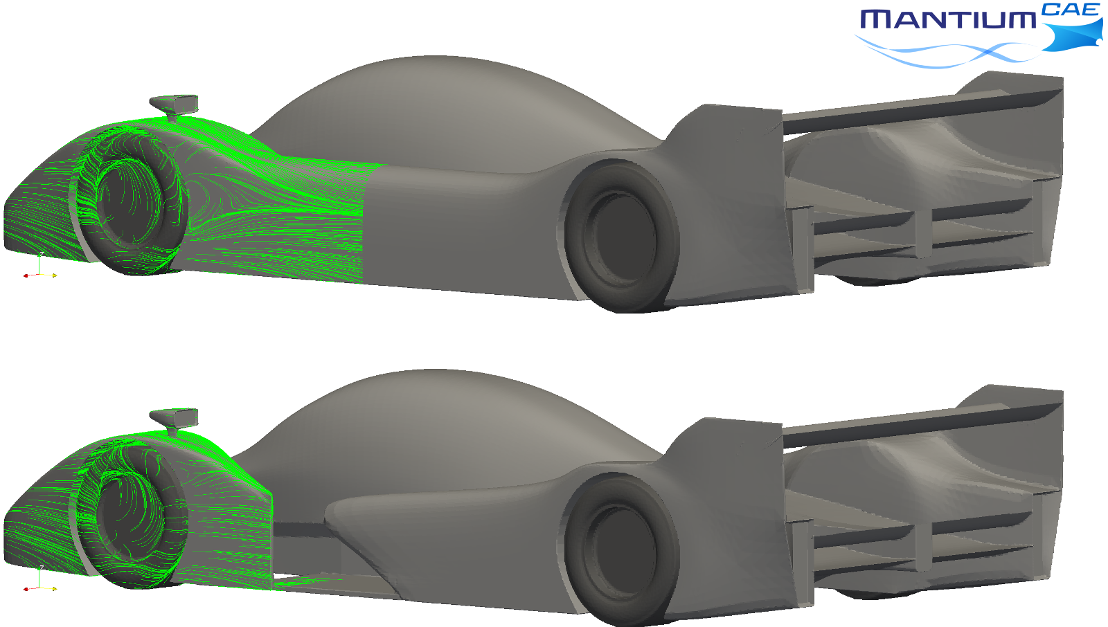
Here are two pictures with stream lines entering the gap in my front wing and also on the sides:
...
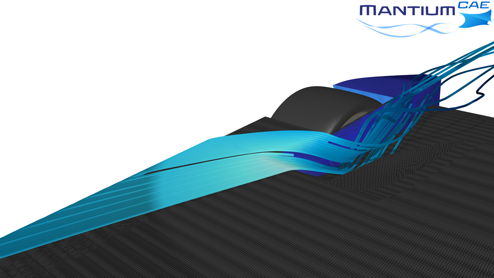
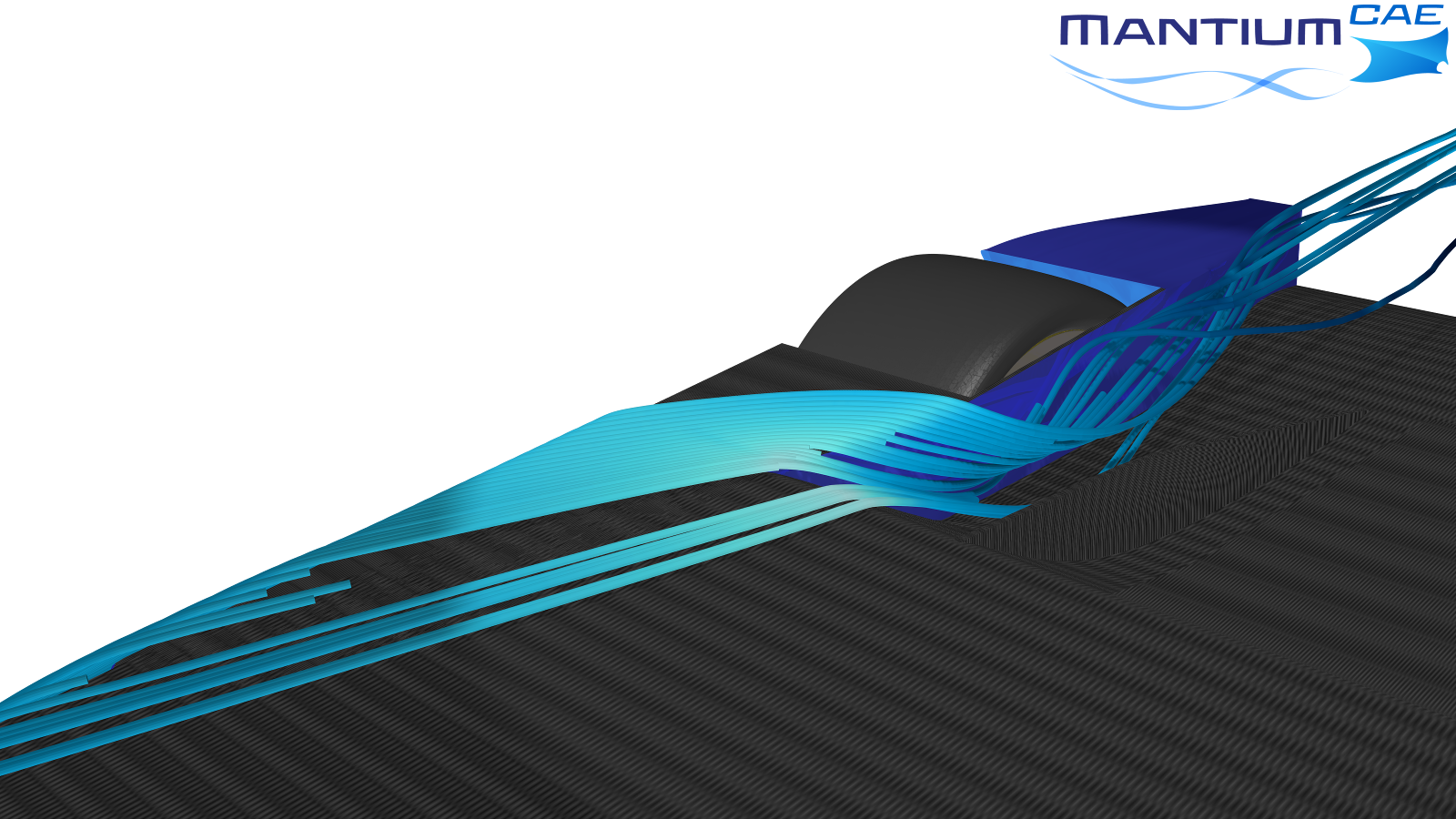
So time to look at the numbers:
The open version has 1.7% more drag and 1.4% more down force. The CoP is shifted forward 5cm. So maybe the front wing airflow is indeed slightly improved.
Some quick mental arithmetic on those numbers (using your Round 4 results as a baseline: Cd.A of 1.03, Cl.A of 5.02 and COP of 1.567m) suggests that opening up the side pods has increased the front downforce by 5% and decreased the rear by about 2%, with an efficiency (Lift:Drag) of about 4:1...The open version has 1.7% more drag and 1.4% more down force. The CoP is shifted forward 5cm. So maybe the front wing airflow is indeed slightly improved.

It was a useful exercise in its current form though, as it just goes to show that once you've got to a certain level of performance, there are no "easy wins", even if you make what looks to be a reasonably large charge....variante wrote: I'm quite sure that a generically designed device will lead to a generic, probably unsatisfactory, result. Instead, if we start designing something to achieve a precise target, the result will be clearer and the device itself will be proven fully effective.
I have made the changes you suggested to the diffuser. I have move the crash structure forward to roughly the same position as you suggested along with shrouding it in a teardrop. I have also changed the front suspension cover to a teardrop shape as the one on the car originally was like a curved L shape rotated to cover the suspension.machin wrote:Hi Ric,
I took the liberty of looking through your previous designs and your results and I see that you already had a lot of those features on your previous cars....
I think your round 3 car looked pretty good... I'm wondering if it might make a better starting point, if for no other reason than you already have a set of aero coefficients with which to work with...
http://i.imgur.com/bPGI0my.jpg
First thing would be to tidy up the side pod/crash structure....
The next step would be to graft on the diffuser exit from your round 4 car:
http://i.imgur.com/nNQGlTL.jpg
Both those should tidy up the car, and reduce drag a little, but don't expect miracles.
The round 3 car had quite a front bias to its downforce, which essentially means the front end is producing a lot more drag for additional downforce that the car can't utilise. I would be inclined to lose one element from your upper front wing: this should improve your balance and overall efficiency.
Again, we can't expect miracles with these changes, but I think that leaves you with a good basis to start with. I took the liberty of photoshopping what the car might look like (a picture paints a thousand words and all that).
http://i90.photobucket.com/albums/k248/ ... uydt0f.jpg
There's an interesting article in the latest Racecar Engineering in which they made an F1 car model and subjected some changes on it to see what effect they had: trimming a small amount OFF the diffuser width manipulated a vortex sufficiently to increase downforce by 10% AND reduce drag: i think the moral here is that once you've got the basics sorted there are going to be no easy wins: to match the front runners requires some pretty in-depth CFD analysis.
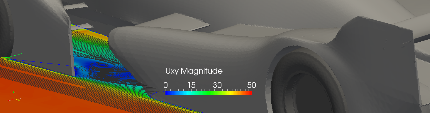
Perhaps you could post some CFD images from under the Diffuser of your Round 4 car and we can try and figure out what's going on. Start with a surface pressure plot...?

