
This website also has other nice photos of the Honda F1 car.
http://www.scotts-se7en.co.uk/hondaf1_orange.htm

Nope, mine's just a lowly 245hp Honda 4 banger. The V8 Atom is owned by "the other dp". Hopefully he'll have the bugs worked out of that one soon.flynfrog wrote:Do you happen to have a V8 atom by chance
I have been following the other onedp35 wrote:Nope, mine's just a lowly 245hp Honda 4 banger. The V8 Atom is owned by "the other dp". Hopefully he'll have the bugs worked out of that one soon.flynfrog wrote:Do you happen to have a V8 atom by chance

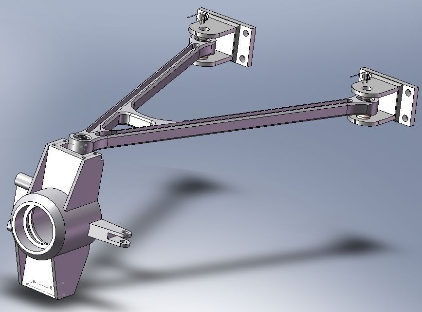


They may not see bending loads, but they certainly do see compression. A flat plate will buckle at a very low compression load, so having some section is very important. It doesn't matter whether it's an "H" or an "I", and the way you've drawn it is far easier to make.mep wrote:So first of all you don't need the H-profile on the a-arms because they don't see any bending moments.
You can make them very simple by using a laser cutted and welded steel plate or
some steel tubes.
It will make them lighter compared to stiffness, aero efficient and cheap to manufacture.
Look at this:spacepig wrote:
They may not see bending loads, but they certainly do see compression. A flat plate will buckle at a very low compression load, so having some section is very important. It doesn't matter whether it's an "H" or an "I", and the way you've drawn it is far easier to make.

I didn't say a tube would buckle, I was responding to the suggestion to make wishbones from flat plate(!). Fabricated wishbones are pretty obvious, but there's actually a lot to be said for machining them from billet. Production car wishbones tend to be forged or cast with an H beam section very similar to what the OP drew.mep wrote: The tube will not buckle that easy.
This solution is much better than the one milled from alu.