Suspension uprights?

Here are our CFD links and discussions about aerodynamics, suspension, driver safety and tyres. Please stick to F1 on this forum.
Jersey Tom
Jersey Tom
166
Joined: 29 May 2006, 20:49
Location: Huntersville, NC

Re: Suspension uprights?

Post

tok-tokkie wrote:
Jersey Tom wrote:Image
Jersy Tom, I do some cnc machining but don't follow that fully. Are you saying that if you use a 6mm cutter then the maximum depth should be 18mm? (I apprecaite that you are going to go down to that depth in several passes.) I am more or less self taught so am interested.
Yep, basically. To really be able to run high spindle speeds and chiploads (HSM/HEM) you want to have the most rigid cutter you can have, to mitigate tool chatter.

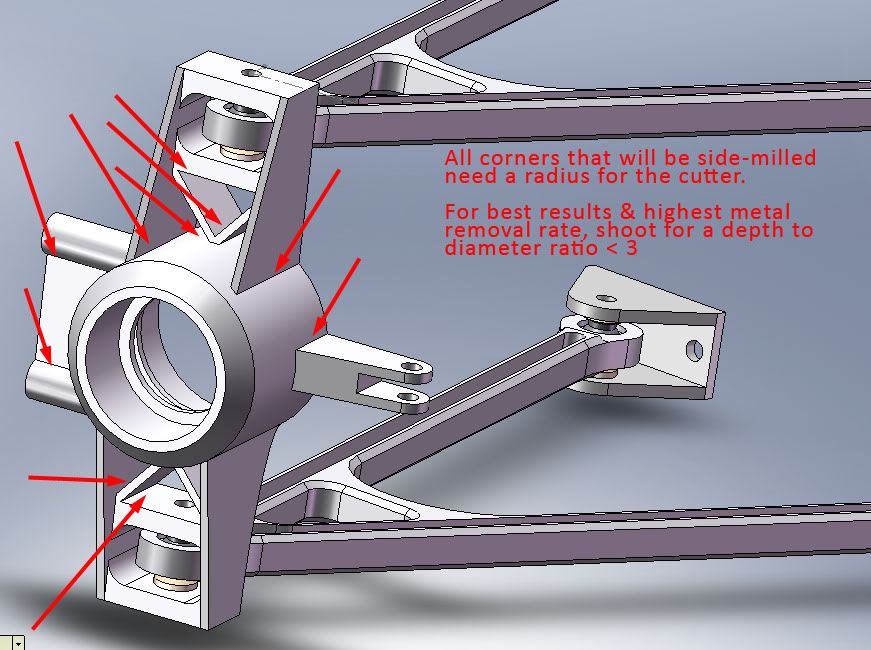
A 6mm cutter with a 6mm axial LOC would be a "stub length" tool, very rigid. 12mm LOC "normal length" and 18mm "extended length." With carbide tooling I try to stay below that 3x diameter ratio. When you get beyond that you have to generally dial the feeds and speeds down to prevent chatter, and then your efficiency and throughput go to crap.
Grip is a four letter word. All opinions are my own and not those of current or previous employers.

riff_raff
riff_raff
132
Joined: 24 Dec 2004, 10:18

Re: Suspension uprights?

Post

n smikle,

F1 uprights are normally wire EDM cut 6Al-4V titanium plate. They are wire cut in order to produce section thicknesses that cannot be produced with conventional milling operations.

Image

Titanium is used because the >1500degF heat loads from the carbon brakes can be quite significant. An aluminum upright is not safe structurally beyond about 250degF.

As for pushrod attachments, the front pushrods are usually attached to the lower A-arm, as close to the lower ball joint as possible in order to reduce bending in the lower A-arm. The front pushrods are not attached to the upright because the upright must rotate for steering. Also make sure that your front suspension parts have adequate clearance at full steering lock and full bump or droop.

The rear pushrods are normally attached to the upright, just forward or aft of the drive shaft, and in a position where they will clear the underwing during full droop.

Most racing brake caliper attachments are now radial, as the sketch shows.

But the front steering arm is usually a separate piece, so that it can be changed in order to tune your suspension for negative or positive Ackerman.

Also, at least one of either the upper or lower ball joints is usually made detachable so that you can adjust your camber using shims.

Finally, since all of the members of a double A-arm pushrod suspension are loaded primarily in tension or compression, be sure to analyse for adequate buckling strength.

Good luck.
Terry
"Q: How do you make a small fortune in racing?
A: Start with a large one!"

User avatar
PlatinumZealot
554
Joined: 12 Jun 2008, 03:45

Re: Suspension uprights?

Post

Interesting...Thanks for the info..

(Becuase they are always covered up I didn't know F1 uprights looked were that)

The buckling load was 1.6 times the design load of the arms (~1000lbs).


I think I am done with the final concept of my rear upright now. My brain is exhausted. :oops: Just to much different ways of designing these things..Almost burst a vessel. Never gave uprights much attention until now.. A grossly overlooked part!

I still have to do some research one the various ways of holding wheel bearings so I can put those details in. So you can take it as incomplete.

Push rods are not shown..

Image
(Arm mounts look out of place (steel box section) everything else all CNC cut and stuff..)

Image

That's it from me for now, I'm giving my self a break next week i do the fronts uprights.
πŸ–οΈβœŒοΈβ˜οΈπŸ‘€πŸ‘ŒβœοΈπŸŽπŸ†πŸ™

User avatar
PlatinumZealot
554
Joined: 12 Jun 2008, 03:45

Re: Suspension uprights?

Post

I am working out the dimensioning as of now.. But the fastener to hold the upper CA bearing (on the top upright) of this Ferrari upright interested me. What type of fastener is that?

Image
πŸ–οΈβœŒοΈβ˜οΈπŸ‘€πŸ‘ŒβœοΈπŸŽπŸ†πŸ™

User avatar
PlatinumZealot
554
Joined: 12 Jun 2008, 03:45

Re: Suspension uprights?

Post

I have another problem with the "head" of the control arm. when I make the "head" thin enough (~9mm) so that a Staking tool can be used to fit the bearing.. the result is that, that part of the arm fails (Aluminum) when I apply my test load to it.

I am afraid I might have to use bearings several sizes bigger than that required so that the arm is thick enough.. (if I am to design the arms to use the staking method.)

Is there another way around this?

I will show you the test results.

HEre is a picture of the staking tool.. I notice that around the bearing has to be no thicker than the bearing itself.

Image
www.ahrinternational.com
πŸ–οΈβœŒοΈβ˜οΈπŸ‘€πŸ‘ŒβœοΈπŸŽπŸ†πŸ™

marcush.
marcush.
159
Joined: 09 Mar 2004, 16:55

Re: Suspension uprights?

Post

how does it fail exactly? without details nobody can give advice other than general and obvious ones...

spacepig
spacepig
0
Joined: 14 May 2009, 22:48

Re: Suspension uprights?

Post

Why is the upright so shallow? You probably need more space between your wheel bearings.

You don't have to stake the bearings- you can increase the thickness of the wishbone and retain the monoballs with spirilox or snap rings. Or you can just increase the diameter of the end...

Shrek
Shrek
0
Joined: 05 Jun 2009, 02:11
Location: right here

Re: Suspension uprights?

Post

I remember Racecar Engineering had an article last yeart about the then new titanium uprights for Epilson Euskadi's LeMans racers and they had stiffening rings and a lot of very high tech features even for F1.
Spencer

riff_raff
riff_raff
132
Joined: 24 Dec 2004, 10:18

Re: Suspension uprights?

Post

n smikle,

For fatigue sensitive application, with reversing load conditions, like an A-arm, you're probably better off (and safer) using welded alloy steel (or even machined titanium if you can afford it).

I'm assuming you chose aluminum for your A-arm because it's lightweight, reasonably priced, and can be easily machined in one piece to the shape you want. But aluminum does not do well in structures that experience reversing load cycles. In order to design an aluminum A-arm with adequate structural strength margins, you will need to use a very conservative stress limit. As a result, the aluminum A-arm ends up being no lighter than a welded alloy steel part. Plus, the benefit of the alloy steel part is that this material, unlike aluminum, has a very well defined fatigue endurance limit.

Having said that, I'm glad to see that you're doing structural tests of your parts to validate your analysis, before you race them. Very professional.

A standard spherical bearing with a 9mm outer race thickness would have a static radial capacity of about 18,800lbf (85kN):

http://aurora.thomasnet.com/item/produc ... s?&seo=110

If you assume the A-arm thickness is the same, the outer radius of the A-arm around the bearing bore would need to be at least 1.85 inches (47mm or about 1.8 times the bearing OD) to equalize the strength capacity of the bearing and A-arm, using a simple 20ksi material allowable for the aluminum. Looking at your sketches, it doesn't appear that you have anything close to that. In fact, the E/D margin for the bearing bore appears to be even less than 1.0, which is generally not considered good design practice.

Good luck.
Terry
"Q: How do you make a small fortune in racing?
A: Start with a large one!"

User avatar
PlatinumZealot
554
Joined: 12 Jun 2008, 03:45

Re: Suspension uprights?

Post

Thanks.. I am aware of the fatigue loading, I have a much simpler steel tube model but I am just trying something new by using aluminum. I also compare the weights between the two as I go along (though not in a serious manner yet). When I take a look on the SN curve of 6061 I will let you know my design limit. (I am unfamiliar with fatigue for aluminum)I have done the stress tests and will soon post the pictures of the results.
πŸ–οΈβœŒοΈβ˜οΈπŸ‘€πŸ‘ŒβœοΈπŸŽπŸ†πŸ™

User avatar
mep
29
Joined: 11 Oct 2003, 15:48
Location: Germany

Re: Suspension uprights?

Post

Hm I am still concerned about your pushrod attacking point.
I wonder why nobody else is talking about it.
Ok, it is not that bad as on the front, where you wouldn't be able to steer the car but you will still get some forces into your track rod under bump/rebound.
I can see this forces being quite high, what demands your track rod to be much stronger and heavier. I also cant see your structure being optimised for that load path from the pushrod to the track rod.

Can anybody enlighten my on that case?
Image

User avatar
PlatinumZealot
554
Joined: 12 Jun 2008, 03:45

Re: Suspension uprights?

Post

Because of the offset of the push rod attachment from the vertical axis? It will try to "turn" the upright. Good observation.. =D>

That means the track rod has to counteract a portion of the moment from the Pushrod. I made the arm on top to the track rod longer to help reduce the force in the track rod.

This is all because I didn't want to put the upright on the control arm.

If the lower control arm was steel (or much thicker) putting the PushRod on it would definitely avoid that problem. I also have to have the pushrod coming out at an angle to avoid the drive shaft.

What do you think? Put the pushrod on the lower control arm? This means that the bearing on the lower control arm has to take the load to the Pushrod now.

I will explore both options.. this part of the car is harder than I expected.. the tube frame and crash structure was much easier than this. :wtf:
πŸ–οΈβœŒοΈβ˜οΈπŸ‘€πŸ‘ŒβœοΈπŸŽπŸ†πŸ™

User avatar
PlatinumZealot
554
Joined: 12 Jun 2008, 03:45

Re: Suspension uprights?

Post

n smikle wrote:Thanks.. I am aware of the fatigue loading, I have a much simpler steel tube model but I am just trying something new by using aluminum. I also compare the weights between the two as I go along (though not in a serious manner yet). When I take a look on the SN curve of 6061 I will let you know my design limit. (I am unfamiliar with fatigue for aluminum)I have done the stress tests and will soon post the pictures of the results.
I got from a source that the endurance limit of 6061 is 14Ksi (or 9,650 N/cm^2). This might be for a shiny surface though. http://www.espimetals.com/tech/aluminum6061-t651.pdf


I also read that automobile manufacturers generally use a safety factor of 4 for the suspension (impact etc).. That is is really going to lower the design stress now :oops: .. call it 2,400 N/cm^2..
πŸ–οΈβœŒοΈβ˜οΈπŸ‘€πŸ‘ŒβœοΈπŸŽπŸ†πŸ™

User avatar
mep
29
Joined: 11 Oct 2003, 15:48
Location: Germany

Re: Suspension uprights?

Post

If the lower control arm was steel (or much thicker) putting the PushRod on it would definitely avoid that problem. I also have to have the pushrod coming out at an angle to avoid the drive shaft.
That is not the problem, it is not so difficult to make the short distance from the attacking point to the bearing stiff.
The pushrod and the drive shaft is always a problem, that is why I suggested you much earlier to make a basic skeleton in CAD of all your components.
It will get even more difficult when you want to put your suspension to the rest of the car.
Remember your pushrod has to operate the springs and the anti-roll-bar.

At the front you will need to put the pushrod on the a-arm anyways, so why to bother doing two different solutions.
The only problem I could see is your bearing might not be able to take the vertical load, so this might be a reason to turn it 90 degree or you take a bearing who is capable of doing this.

User avatar
PlatinumZealot
554
Joined: 12 Jun 2008, 03:45

Re: Suspension uprights?

Post

The basic skeleton is there but it doesn't account for the volume of the parts so that is partially why the situation is like this. But I have it under control as haphazard as it seems on this page 8) . This method is a "natural selection" method so The second time around I will be more efficient for sure.

It is an odd design.. but it is mechanically sound.

Image

Lets calculate..

Assuming the tie rod can only take the force caused by the spinning of the upright.

The car goes over a bump and there there is a 1000lbs of upward force in the upright. Let us say Pushrod is the hypotenuse of a triangle of height 0.3m, base 0.5m that goes from the bell crank to the base of the upright:

The pushrod will have 1943lbs in compression.
The sideways component will be 1666lbs pushing outward. So This will try to spin the upright.

The top arm gives mechanical advantage of say, 4 for the tie rod..so the tie rod will get 1666/4 = 416.5lbs in pure tension. And the Control arm will get 1249.5 lbs from that load. (So an effect is that it reduces the load on the Control arm bearing).

The tie rod is steel.. a 3/4 inch 0.065 thickness chrome steel tube. Axial stress = Load/area = 416.5/((.75^2-(.75-0.065)^2)*pi/4) = 5 685.38 psi
UTS of 4340 = 100ksi.. Sn = 50ksi...Safety factor of 4 so design stress = 12.5 Ksi
SAFE!

So it is mechanically sound at least. Just a different design.

Not that I have to use this design. I can still drop it if there are other disadvantages.
πŸ–οΈβœŒοΈβ˜οΈπŸ‘€πŸ‘ŒβœοΈπŸŽπŸ†πŸ™