KERS CONTROL UNIT

All that has to do with the power train, gearbox, clutch, fuels and lubricants, etc. Generally the mechanical side of Formula One.
donskar
donskar
2
Joined: 03 Feb 2007, 16:41
Location: Cardboard box, end of Boulevard of Broken Dreams

Re: KERS CONTROL UNIT

Post

I love this quote from Ecclestone:
Ecclestone would prefer the teams concentrated on sport and left the saving of the planet to the relevant authorities. "I have always been against KERS. Whatever they use in F1 they won't use in a road car, but if that is to be the idea then why not develop it in touring cars. It costs a lot of money when we are trying to save it."
Enzo Ferrari was a great man. But he was not a good man. -- Phil Hill

xpensive
xpensive
214
Joined: 22 Nov 2008, 18:06
Location: Somewhere in Scandinavia

Re: KERS CONTROL UNIT

Post

I'm a little curious over the type of KERS-batteries employed, when I don't think that the charging and discharging (60 kW) of 400 kJ within seconds is that simple.

As a comparison, imagine running a mammoth 60 kW(80 Hp)starter-motor with your car-battery for 6 seconds, then charge it full within what, twenty?
Now repeat that procedure at least 60 times over a period of less than two hours.

Any first-hand info on this scarbs?
"I spent most of my money on wine and women...I wasted the rest"

User avatar
djos
113
Joined: 19 May 2006, 06:09
Location: Melbourne, Australia

Re: KERS CONTROL UNIT

Post

It's unlikely that conventional Batteries will be used, most F1 teams have hinted at using super-capacitors which can charge/discharge far more rapidly than any current battery technology.
Last edited by djos on 27 Jan 2009, 10:29, edited 1 time in total.
"In downforce we trust"

User avatar
WhiteBlue
92
Joined: 14 Apr 2008, 20:58
Location: WhiteBlue Country

Re: KERS CONTROL UNIT

Post

I suspect that they just use a bunch of polymer/ion batteries. You can manufacture them into very unusual shapes. Appel has a nice video of the manufacturing process in their promotion for the 17" MacBookpro on their web site. Those batteries have approximately 1000 full load cycles. If they use partial loads you get more cycles in proportion to the how much of a full load you empty. This would tie in with the information on batterie life we heard.
Formula One's fundamental ethos is about success coming to those with the most ingenious engineering and best .............................. organization, not to those with the biggest budget. (Dave Richards)

scarbs
scarbs
393
Joined: 08 Oct 2003, 09:47
Location: Hertfordshire, UK

Re: KERS CONTROL UNIT

Post

xpensive wrote:I'm a little curious over the type of KERS-batteries employed, when I don't think that the charging and discharging (60 kW) of 400 kJ within seconds is that simple.

As a comparison, imagine running a mammoth 60 kW(80 Hp)starter-motor with your car-battery for 6 seconds, then charge it full within what, twenty?
Now repeat that procedure at least 60 times over a period of less than two hours.

Any first-hand info on this scarbs?
Teams wil use lithium cells, Renault are supplied by Saft, with around 60 cells put into a battery. The charge (C) rate will be high enough, as the system will charge so many cells at once.

xpensive
xpensive
214
Joined: 22 Nov 2008, 18:06
Location: Somewhere in Scandinavia

Re: KERS CONTROL UNIT

Post

Thanks again scarbs, sounds exotic though. Another thing, I have so far taken for granted that these KERS-systems would be all-DC, but with modern electronics, such as AC-frequency converters and so on, maybe that's not for certain?
"I spent most of my money on wine and women...I wasted the rest"

Conceptual
Conceptual
0
Joined: 15 Nov 2007, 03:33

Re: KERS CONTROL UNIT

Post

Scarbs,

Can you ask why they are all going with the old tech of Lithium Ion batteries instead of the more advanced Lithium Polymer type?

From what I have seen, the LiPo crushes the Li+ batteries in almost every catergory...

Maybe it is down to charge/release times....

If you have any info about this, please share!

Lithium battery FAQ: http://www.rcgroups.com/forums/showthread.php?t=209187

pipex
pipex
6
Joined: 31 Jul 2008, 09:27
Location: The net

Re: KERS CONTROL UNIT

Post

xpensive wrote:Thanks again scarbs, sounds exotic though. Another thing, I have so far taken for granted that these KERS-systems would be all-DC, but with modern electronics, such as AC-frequency converters and so on, maybe that's not for certain?
If they are using batteries to store energy they are using DC...
The motors used seem to be brushless permanent magnet ones. People call them brushless DC, but they are really synchronous generators (some kind of AC machine), so they need a converter that acts as an active rectifier/inverter depending on the side (that is they convert AC from one side to DC in the other side and viceversa). I think that the matrix converters is a good converter topology to use. Another converter they could use is a traditional IGBT based three phase bridge.
From what scarbs shared with us, F1 systems look a lot simpler than road relevant ones...
I don't know of any traditional device in which you could store AC energy. Maybe in a magnetic field rotating device?, superconducting magnets?.
Thanks scarbs, looking forward for more details :)
"We will have to wait and see".

pipex
pipex
6
Joined: 31 Jul 2008, 09:27
Location: The net

Re: KERS CONTROL UNIT

Post

To get regenerative operation of a drive you need operation in four quadrant, that is a bidirectional energy flow. We will assume a induction machine for simplicity.
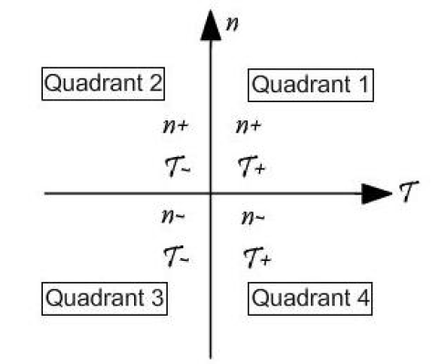
Four quadrant operation relates to the signs of the speed (n) and torque (t).

First quadrant: Positive torque, positive speed.
Motor fed by the batteries.
Second quadrant: Negative torque, positive speed.
Motor is braking and energy returns to batteries.
Third quadrant: Negative torque, negative speed.
Motor fed by batteries but backwards movement.
Fourth quadrant: Positive torque, negative speed.
Motor is braking, energy returning to batteries in backward movement.

It seems that only first and second quadrant should be needed in a KERS.

Image

Changing the torque/speed references of the controller makes possible the regenerative operation of the bidirectional rectifier/inverter.

The converter used for this operation could be a bidirectional 6 switch bridge.

Image

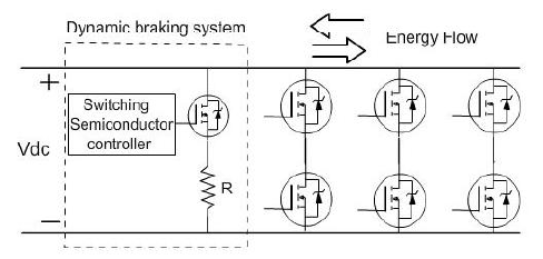
DC Side (left) is where batteries should be connected (or supercapacitors, flywheels or other DC storage) and AC side is where you put the motor/generator (right).
Its not clear in the drawing but the motor is connected in the middle points between the switches.
A three phase connection is used due to the big power transfer. A single phase converter need less components, but a semiconductor for this application could be non existant.
The dynamic braking system in the figure is there to absorb overcharging of the dc bus and acts as chopper regulating dc link instantaneous voltage. In this way excess power flow is burnt in the resistor in series with the switch.

I hope that this is useful for something... i just wanted to contribute something for the lots of things that i learn here related to mechanics :)

Note that the topology should be similar for a permanent magnet motor, but the control of the switches will change. If i have more time i will write something about it.

Regards
"We will have to wait and see".

xpensive
xpensive
214
Joined: 22 Nov 2008, 18:06
Location: Somewhere in Scandinavia

Re: KERS CONTROL UNIT

Post

For pipex:
I would like to return the courtesy by admitting that as a pure mechanical engineer, I am most greatful for your info. Anyway, storage needs to be DC, I get that much, but I did suspect that the MGU was AC after all, while the rectifier/inverter looks simple enough at least on paper.
Q's:
- How is the frequency back to the MGU contolled?
- Some positings here mentions "cooling of KERS", which confuses me, which part needs cooling?
"I spent most of my money on wine and women...I wasted the rest"

User avatar
WhiteBlue
92
Joined: 14 Apr 2008, 20:58
Location: WhiteBlue Country

Re: KERS CONTROL UNIT

Post

Re AC/DC: I would think that the Williams electrical Flywheel would produce AC. Nevertheless that also will require an inverter to give it the necessary modulation to drive the motor.

Re cooling of KERS: Both the MGU and the drive unit will need water cooling for maximum performance. Water cooled Units tolerate much higher over loads both in spike as in permanent loading.
Formula One's fundamental ethos is about success coming to those with the most ingenious engineering and best .............................. organization, not to those with the biggest budget. (Dave Richards)

User avatar
djos
113
Joined: 19 May 2006, 06:09
Location: Melbourne, Australia

Re: KERS CONTROL UNIT

Post

Conceptual wrote:Scarbs,

Can you ask why they are all going with the old tech of Lithium Ion batteries instead of the more advanced Lithium Polymer type?

From what I have seen, the LiPo crushes the Li+ batteries in almost every catergory...

Maybe it is down to charge/release times....

If you have any info about this, please share!

Lithium battery FAQ: http://www.rcgroups.com/forums/showthread.php?t=209187
Holy crap!! I didn't realise how difficult LiOin/LiPo batteries where to work with! No wonder RedBull had a fire while testing batteries! :shock:
"In downforce we trust"

pipex
pipex
6
Joined: 31 Jul 2008, 09:27
Location: The net

Re: KERS CONTROL UNIT

Post

xpensive wrote:For pipex:
I would like to return the courtesy by admitting that as a pure mechanical engineer, I am most greatful for your info. Anyway, storage needs to be DC, I get that much, but I did suspect that the MGU was AC after all, while the rectifier/inverter looks simple enough at least on paper.
Q's:
- How is the frequency back to the MGU contolled?
- Some positings here mentions "cooling of KERS", which confuses me, which part needs cooling?
Hi xpensive :)
Q1: The frequency back to the MGU is controlled modifying the on/off pattern of the switches. Its controlled by the speed reference you want the motor to spin. The speed command is fed to another control that generate specific current references, and that references produce a characteristic switching pattern (this is complex, i don't want to remember my AC drives class :( ). This depends on the type of the machine (induction or permanent magnet). The rectifying/inverting mode is dictated by this reference generation, and that modifies the power flow.
You can set a torque reference too, and this will change the optimum operating speed. This all depends on the model of the machine and the control mode. For vehicle applications i think that speed reference is the control mode. Torque can be set as a reference too but i don't know if this is what is needed.
Q2: In a normal motor you have forced convection cooling with air. Electric motors have an integrated fan and special casing that allows efficient air heat transfer. I think that in KERS you need water cooling for the motor. Drives for vehicle applications independant of the type (AC or DC) need water cooling for the semiconductors, due to the high power transfer. So, the motor and the unit that has the switches need cooling.
"We will have to wait and see".

pipex
pipex
6
Joined: 31 Jul 2008, 09:27
Location: The net

Re: KERS CONTROL UNIT

Post

WhiteBlue wrote:Re AC/DC: I would think that the Williams electrical Flywheel would produce AC. Nevertheless that also will require an inverter to give it the necessary modulation to drive the motor.
You are right WhiteBlue, i forgot completely what occurs with flywheel storage. Here i think that another couple of problems arise.
If the flywheel unit is used as a replacement of batteries they can output DC or AC, it depends on the converter used. If you want direct power transfer you should use a matrix/direct converter. They convert AC signals to another AC signal of another frequency, and could use the same basic control (a bit modified) method. If you use another converter, you need a dc link, so you will need 2 bridges. One to pass the energy from AC to DC, and other to pass from DC to AC. Its not possible to transfer directly AC to AC, without using a direct converter. One of the converters can be integrated to the flywheel or be external one connected in a separate unit. So, the flywheel could be seen as a DC terminal blackbox or a AC terminal blackbox, depending if this converter is integrated or not.
"We will have to wait and see".

xpensive
xpensive
214
Joined: 22 Nov 2008, 18:06
Location: Somewhere in Scandinavia

Re: KERS CONTROL UNIT

Post

Again, most informative pipex, thanks a lot. Then I guess it would make sense to intergrate cooling of the MGU and electronics with the main engine cooling circuit?

As for different reports of over-heated batteries, no need for cooling there?
"I spent most of my money on wine and women...I wasted the rest"