Ringo F1 design

Post here information about your own engineering projects, including but not limited to building your own car or designing a virtual car through CAD.
User avatar
matt21
86
Joined: 15 Mar 2010, 13:17

Re: Ringo F1 design

Post

What comes to my mind at the moment I´m looking at Ringos idea:

Why not using flat panel heat exchangers designed as part of the undertray in order to energize the flow in the diffusor? If you use enough area it should work.
So maybe a "KERS-cooling-driven diffusor".
Or are there any limitations on the materials to be used for the undertray?

User avatar
ringo
227
Joined: 29 Mar 2009, 10:57

Re: Ringo F1 design

Post

It's feasible, though the pumping losses would be high to pump fluid through such a large area.
Radiative heat coming from the track is also a factor.

Flat plates work, but fins are much more effective becuase of the higher surface area in a small volume.

The finned heat exchanger concept can be applied to the rear wings as well. With the fins running longitudinally in the belly of the wing.
The required area wont be much since a KERS cooler doesn't seem to be such a big device.

Image

It would be good to place the cooler nearer the motor and batteries. This is why somewhere near the cockpit region is good.
For Sure!!

User avatar
forty-two
0
Joined: 01 Mar 2010, 21:07

Re: Ringo F1 design

Post

Nice Work Ringo!

I am somewhat amazed that nobody has pointed out that the Williams' new "bucket" scalloped rear wing appears to be directly inspired by your RW design. do Williams F1 follow this site perhaps?

Image

Image

The additional sculpting to the lower element is different to your design, but the bit cut out of the back of the lower element and the corresponding extension to the upper element is the same, if a little bit less extreme.

I guess it wouldn't actually be a bad plan for all F1 teams to have an intern do a daily check on this and a few other sites to see what's being said. I am pretty sure a number of journalists do so at very least!
The answer to the ultimate question, of life, the Universe and ... Everything?

gridwalker
gridwalker
7
Joined: 27 Mar 2009, 12:22
Location: Sheffield, UK

Re: Ringo F1 design

Post

Williams tested that wing quite some time ago; Canada weekend, I believe.
"Change is inevitable, except from a vending machine ..."

User avatar
forty-two
0
Joined: 01 Mar 2010, 21:07

Re: Ringo F1 design

Post

gridwalker wrote:Williams tested that wing quite some time ago; Canada weekend, I believe.
You might be right, but can you remember if it was exactly the same. In particular did it have the cutout on the trailing edge of the lower element and the corresponding extension on the leading edge of the upper element?

Not saying you're wrong, I just don't know.

EDIT:
Gridwaler is absolutely right, my mistake.

Ringo, did you draw some inspiration for your RW design from the Williams RW which appeared during FP in Canada?

Actually your design is a bit different. Where yours has bits chopped out of it in the central section, the williams seems to be "bent" downwards. I know I am not explaining that very well, so sorry in advance!
The answer to the ultimate question, of life, the Universe and ... Everything?

User avatar
ringo
227
Joined: 29 Mar 2009, 10:57

Re: Ringo F1 design

Post

This was on the site long before canada.

May be coincidence I guess.

edit looking back i put it on the site on the 19th of june, Canada was the 10-11. But this was in my drawings from the inception of the thread.

I didn't notice that williams had that on the flap. :)

Wonder how the back looks?

I don't like stealing ideas. The car is not real, so it makes no sense to copy and be conservative. Williams seem to be in the desperation mood as well. :lol:

But their bellied wing is actually a copy of Mclarens 2008 wing.
For Sure!!

wuzak
wuzak
446
Joined: 30 Aug 2011, 03:26

Re: Ringo F1 design

Post

ringo wrote:Image

It seems that the Idea is to difficult to fit into the regulated areas lchecked the volumes and an air cooled fined heat sink will be crammed into to tight a volume to be effective. however ithinkafinned heat sink can go at the flanks of the bow of the car. Cooling fluid will flow through this heat sink block of metal. The sink can act as ballast as well. This is a throw back to the gordon Murray concept from the 80's?
You mean the BT46 of 1978, where the system didn't work and was never raced?

User avatar
ringo
227
Joined: 29 Mar 2009, 10:57

Re: Ringo F1 design

Post

Yes. That system was feasible but the cooling load was too big.
Not only that, those plates were not finned.

It deserves a rethink becuase of the lesser demands from kers as compared to a 600hp engine.

Image

The required piping here and the chance it may flex and leak makes this not such a robust design. To put all the rejected heat in the cooling system through flat plates is also too extreme. Not much interaction between the free stream air.

In the case of a KERS cooler, there is a fraction of the power going to the heat exchangers. Much much less heat energy. If KERS is 80 hp it's unlikey that more than 20% of that is coming of as heat energy, much less over the whole lap.
Taking this into account, the heat sink idea is very feasible.
For Sure!!

marcush.
marcush.
159
Joined: 09 Mar 2004, 16:55

Re: Ringo F1 design

Post

you need to cool the MGU ,KERS Controller + the Battery pack ...
The Cooling demands are a matter of the losses in transferring the energy from the MGU through the Controller into the battery pack and back but: as the power is put in quickly and released over short bursts -braking and acceleration it seems reasonable that cooling surface needs can be minimised by having a larger heatsink ..what about the ballast in the car doubling up as a buffer for the energy released? you put in a few tubes and low flow water through it or simply stick the Ballast bricks flush face facing the ground and lower the air density a few notches by this reducing drag ..positioning the ballast on the sides of the step for example .-you cannot put holes in the plank obviously ,but the step from reference to step plane is 50mm high ..so you got maybe 40x20x1500mm on each side
of the tub -tungsten as a finned heat sink/lowest mounted robust heat exchanger. ...maybe you would alloy the tungsten with copper to improve heat transfer ...... that could work out nicely...
It would of course reduce the parts count of the car and reduce CofG height of the car -delete KERS cooler-

what do you think?

User avatar
ringo
227
Joined: 29 Mar 2009, 10:57

Re: Ringo F1 design

Post

I was considering that 50mm gap along the whole floor. It's very simple to have rectangular heat sinks along it.
The thing though is that the radiation from the ground. I'm kind of skeptical about the heat coming off the track.
Also the heat of the engine heating the floor over time.
But i agree that the duy cycle of KERS makes it less demanding on the heat sink.

It's interesting to have the ballast as the heat sink. It would absorb most of the heat by the sheer mass of it. Just 3 or 4 cavities in the ballast running along the floor giving off heat as the flow passes by.

I might try both ideas. The one along the floor and the one on the flanks of the hull of the splitter as indicated by the drawing above.
For Sure!!

marcush.
marcush.
159
Joined: 09 Mar 2004, 16:55

Re: Ringo F1 design

Post

http://www.tungsten-copper.com/german/P ... opper.html

it´s obviously the right material to do that job -so it´s a no brainer not to use ballast as a heat sink.FOR any application you would or could need a heat sink.

I´m amazed nobody had this already ..You can obviously help your electronic components big time -has you cut off the big spikes completely (Start-Pits)from damaging delicate components.Yes it maybe running a tad hotter at times but the thermal shocks are a lot less which is a main issue with early failure especially considering the vibrations present.

I gues we are on something here and let´s see when THIS is showing up on the grid .Formula 1 claims to be the pinnacle and fast reacting-there must be at least one guy per team wading through the web looking for things that can be used?

The heat from the track ? most of the time the track temps are not that high .So there is a lack of delta t maybe on the very hot races trying to keep the batt in a 70 something range and track temp over 50 .Blacktop will soften and breakup at around 80-85°C on its own so you would not be able to race on a track 80°Chot I´d think.
But there is a delta and the car IS moving ,so it will cool.

User avatar
matt21
86
Joined: 15 Mar 2010, 13:17

Re: Ringo F1 design

Post

If you have a cooling area large enough, i think you can overcome the small delta T between the exchanger and the road. Maybe you can use different sink types.

User avatar
ringo
227
Joined: 29 Mar 2009, 10:57

Re: Ringo F1 design

Post

marcush. wrote:http://www.tungsten-copper.com/german/P ... opper.html

it´s obviously the right material to do that job -so it´s a no brainer not to use ballast as a heat sink.FOR any application you would or could need a heat sink.

I´m amazed nobody had this already ..You can obviously help your electronic components big time -has you cut off the big spikes completely (Start-Pits)from damaging delicate components.Yes it maybe running a tad hotter at times but the thermal shocks are a lot less which is a main issue with early failure especially considering the vibrations present.

I gues we are on something here and let´s see when THIS is showing up on the grid .Formula 1 claims to be the pinnacle and fast reacting-there must be at least one guy per team wading through the web looking for things that can be used?

The heat from the track ? most of the time the track temps are not that high .So there is a lack of delta t maybe on the very hot races trying to keep the batt in a 70 something range and track temp over 50 .Blacktop will soften and breakup at around 80-85°C on its own so you would not be able to race on a track 80°Chot I´d think.
But there is a delta and the car IS moving ,so it will cool.
The FIA will find a way to shoot it down.


I will do a simplified calculation, but my brains are unfit from not doing any serious calculations for years.
It's good practice though.
Image

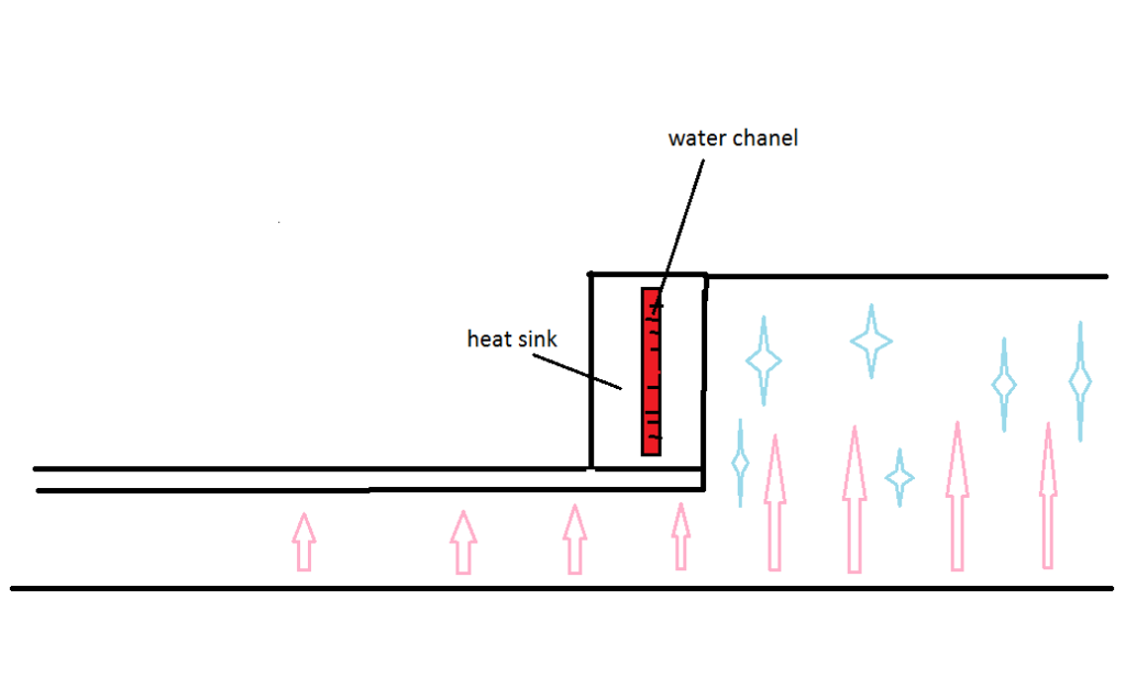
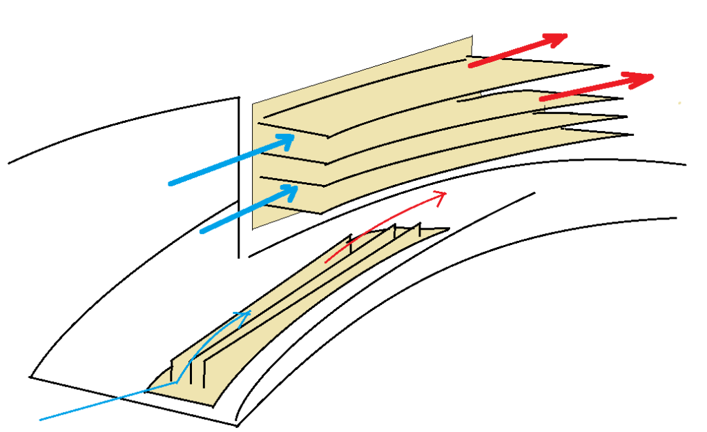
it may look something like this from a cut away view. the ground will be hot and there will be some cooling air passing in that roughly 80mm gap between car and step plane.
Now i think something called Nusselt number is going to come into this, and i can't remember a thing about it. The car is moving and we'll definitely have boundary layer, both thermal and velocity.
But it will spice up the estimates. Time to whip out the heat and mass tranfer books. :P
Kind of tempting to take the solid works route :mrgreen:

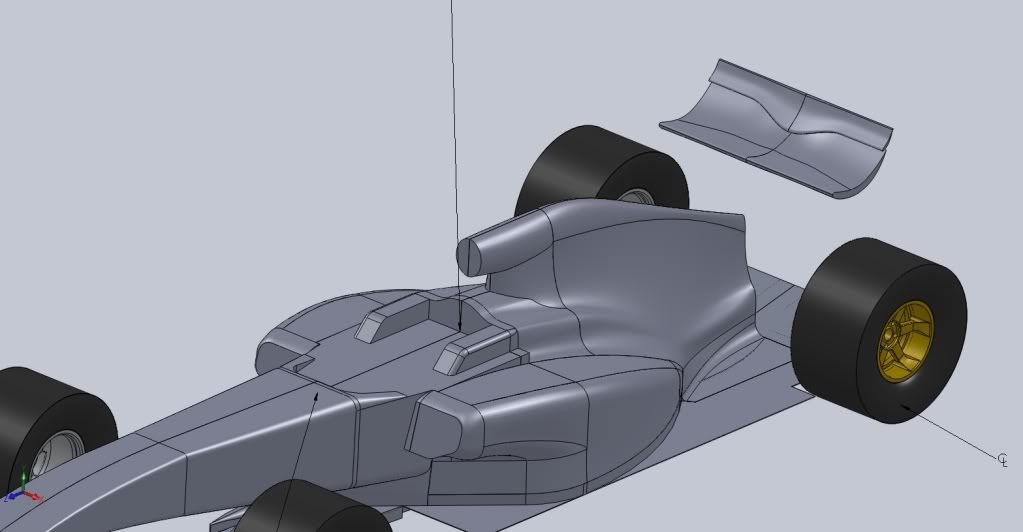
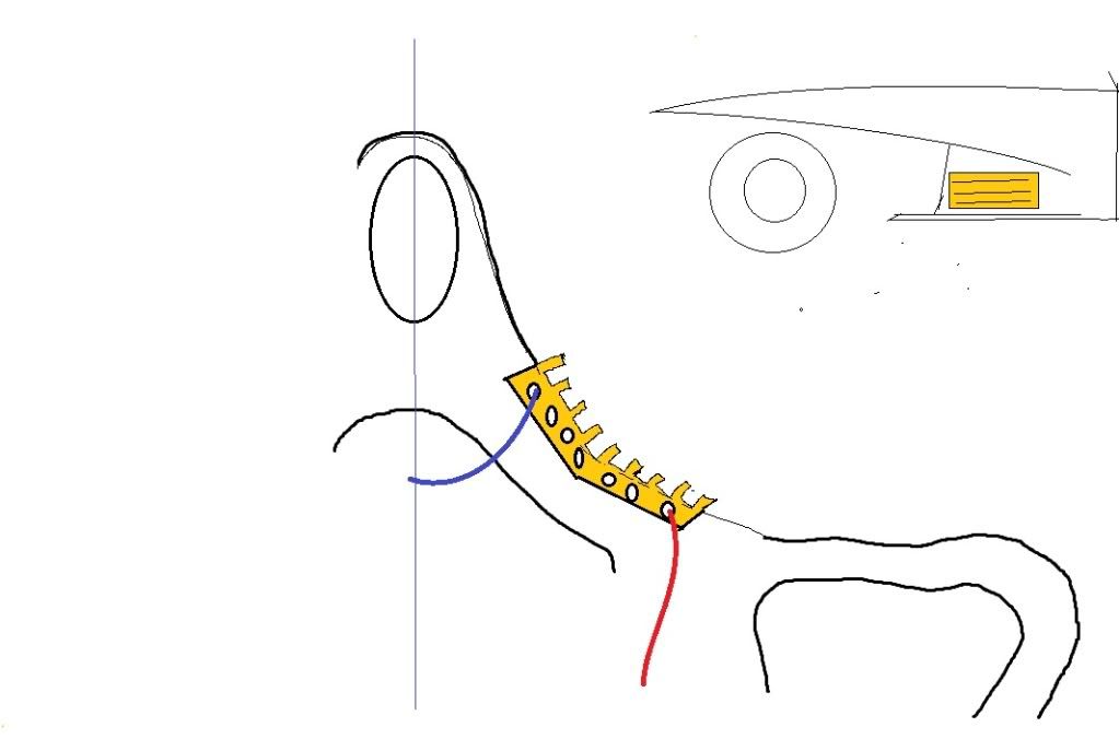
here are the other 2 alternatives. It's in a general balast area. Though one is a little higher. But it beats a radiator on top of the gearbox.
The advantage here is the mass flow and the steadiness and temperature.
Image

these are finned as well.
For Sure!!

wesley123
wesley123
204
Joined: 23 Feb 2008, 17:55

Re: Ringo F1 design

Post

apart from cooling and balast i think these might be pretty usefull here as turning vanes. Piping itself might be a huge downside though, but with the coG these are laid it isnt that much of an downside
"Bite my shiny metal ass" - Bender

marcush.
marcush.
159
Joined: 09 Mar 2004, 16:55

Re: Ringo F1 design

Post

Doubling up as flow conditioners also a nice idea ringo.

The plumning side is a matter of how early you implement the idea .You could well integrate one or two cf tubes into the tub or floor construction and use them as stiffening ribs ...No weight penalty.(apart from thecooling line connectors -wiggins style..did something like that a few years back in cf already.

I feel with the huge workforce available there is no excuse for not having the highest level of integration.

So:any part that has not at least two functionalities is not making it in the car ....something along these lines.