Page 2 of 8
Re: F1 pankl conrod
Posted: 15 Jan 2011, 06:07
by riff_raff
Production engine journal bearing shells have been designed with variable clearances for many years. For ease of production, the main and rod bores are made cylindrical. But the bearing shells are made with a variable wall thickness. I believe Clevite was one of the first companies to do this with their "Delta Wall" bearing design.
It is not so important to have a perfect circular bearing bore at assembly. What matters is the shape and alignment of the mating bearing and journal surfaces under load. The bearing fluid film only supports loads over a very small area, at very high pressures, on one side of the journal at any given instant. The majority of the remaining bearing circumference is unloaded.
Another important factor is the lambda ratio, which is the ratio between the oil film thickness and relative surface asperity heights. Oil film thickness can be adversely affected by edge load concentrations from misalignments or crank pin bending, inadequate oil viscosity, excessive loads, or excessively rough surfaces.
Finally, having excessively small journal bearing clearances is not a good practice. The oil flows through a journal bearing are based on cooling requirements. The effective flow exit orifice area is determined (in part) by the clearance between the bearing and journal. If the clearance is too small to allow adequate cooling oil flow, the bearing materials will overheat and rapidly fail in fatigue.
Nice set of pictures though. Thanks for posting them.
riff_raff
Re: F1 pankl conrod
Posted: 17 Jan 2011, 06:26
by Formula None
Brian, don't mean to bug you, but what's the wrist to crank pin dimension on this guy? Also, wrist pin diameter?
Re: F1 pankl conrod
Posted: 21 Jan 2011, 02:43
by Brian.G
Formula None wrote:Brian, don't mean to bug you, but what's the wrist to crank pin dimension on this guy? Also, wrist pin diameter?
Bug away, thats what it all about!
37.80mm Big end
17.68mm Wrist pin
73.38mm Distance between bore edges,
Wrist to crank pin centres =
73.38mm + (37.80mm/2)> 18.90mm +(17.68mm/2)> 8.84mm =
101.12mm
Measured with a Mitutoyo vernier and not a bore gauge so dont go building an engine with these figures, but you get the idea!
If you want more exact measurements let me know, but I dont know how worn or stressed this rod is.
Brian,
Re: F1 pankl conrod
Posted: 21 Jan 2011, 18:06
by Formula None
Thanks, Brian! I'm building a CAD model for kicks, hard to find general dimensions for these things. Does anyone know how this dimension compares to engines of other F1 eras?
Re: F1 pankl conrod
Posted: 22 Jan 2011, 20:05
by PlatinumZealot
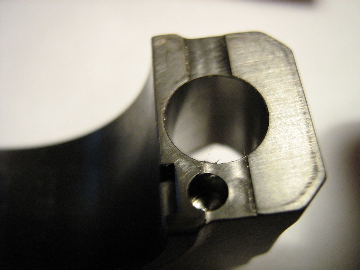
OK. on square channel cut across the bolt hole on the mating face of the big end cap and the slight step to the inside edge.
I was thinking of deformation purposes
in regards to the ovalness bore due to
stretching but:
1. The channel cut does not present a uniform reduction in material, because the dowel goes through it. You can see the dowel hole and everything.
I do not think that the engineer would want to contend with that. So It can be inferred that the deformation is so small ACROSS this area that it is trivial and so the engineer decided that adding the dowel in that spot will not affect the ovalness of the bore. Notice that tension on the caps will not appreciably increase the diameter of the bore acrros at this point because it is perpendicular the load. I Notice that Mr.G said the rod is 38mm across and 37.82 up and down. So I can only assume that the deformation is being controlled
not at where the mating surface is but
through the actual hoop of the cap.
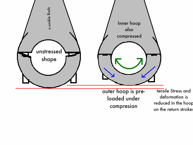
If you look closely you can see the outer edge of the mating surface is slightly higher than the inner edge (the side nearerst the bore).
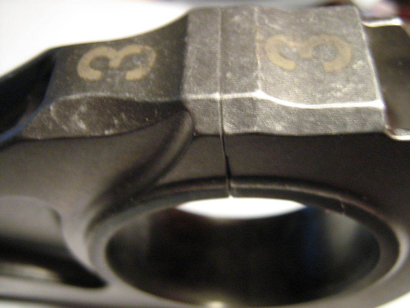
I think that when this is bolted down, the higher outer edge of the mating surface forces the outer fibres of the
hoop into compression. So they are essentially pre-loading the outer "fibres" of the hoop itself into compression. When the connecting rod is on the tensile stroke, this pre-load counteracts the tension. So the diameter in the vertical direction does not grow as much.
This is how I think it works..
THe actual channels now.. I wonder if they are for a measuring instrument such as a feeler gauge or something to check how crushed the big end is upon assembly?
Re: F1 pankl conrod
Posted: 25 Jan 2011, 06:50
by riff_raff
nsmikle,
The shape, stiffness and load distribution around the bolt hole of the assembled rod cap/beam joint is important for optimum bearing performance. If you looked carefully during assembly of the rod, with the bearing shells in place but prior to tightening the rod bolts, you would notice that the bearing shell ends protrude very slightly above the split line. Thus when the rod bolts are tightened, the bearing shells effectively end up installed with a radial preload. This helps prevent fretting between the bearing shell and rod, and is very important.
riff_raff
Re: F1 pankl conrod
Posted: 25 Jan 2011, 11:18
by mep
So riff-raff can you explain why there is this cross cut along the contact surface of rod and cap?
Re: F1 pankl conrod
Posted: 27 Jan 2011, 05:51
by riff_raff
mep,
Can't say for sure why that parting line groove is there.
One guess would be that it reduces the joint contact surface area, and thus increases the surface contact pressures. The higher contact pressures would make the joint somewhat less prone to fretting.
Another explanation might be that the little arches make the clamped structure a little bit more elastic, which is good for fatigue.
riff_raff
Re: F1 pankl conrod
Posted: 27 Jan 2011, 06:05
by ringo
Are these fracture split rods?
Could it be related to the separating notch for the split?
http://www.freepatentsonline.com/6357321.pdf
Paraphrasing:
The holes have a function of achieving a controlled fracture separation along the dividing plane and of avoiding double fractures and cracks.
Re: F1 pankl conrod
Posted: 27 Jan 2011, 06:16
by Formula None
Re: F1 pankl conrod
Posted: 27 Jan 2011, 06:35
by ringo
I saw the machining marks, but you never know. Each manufacturer has their different processes.
Re: F1 pankl conrod
Posted: 27 Jan 2011, 15:09
by Brian.G
No way is the F1 rod fracture split. Fracture split is normally used on sintered steel rods. These are forged Ti with Id imagine the grain/flow running across the cap, and from top to bottom within the rod to insure it stays stable.
Re: F1 pankl conrod
Posted: 27 Jan 2011, 17:42
by ringo
I figured these weren't, i just carelessly put the idea out for consideration. There are some alloys out there than can be fracture split though.
This is Ti, so that method can't be used as you say.
The channel isn't present on the new rod designs, that may be a clue.
Re: F1 pankl conrod
Posted: 04 Feb 2011, 10:22
by F1_eng
The groove in the cap to con-rod mating surface is used to alter the magnitude of the fluctuating load component in the bolt.
The ratio of the total fluctuating load taken by the bolt is dependant on the relative stiffnesses between the two components.
I am not going to say anymore as I feel that is enough information for people to do more research if they wish.
Re: F1 pankl conrod
Posted: 05 Feb 2011, 08:40
by riff_raff
F1_eng,
Regarding your explanation, I'm still a bit confused. The conrod bolt is preloaded in tension at assembly. During operation, the conrod bolt is subject to dynamic tension loads during the exhaust/intake stroke, but these inertia loads are offset by relief of the compressive preload in the clamped conrod parts. They don't affect the total tension load the bolt sees, nor should it affect the stress intensity ratio if the bolt is properly preloaded.
The only parts that would have a fluctuating load during operation are the sections of the rod cap and beam that are preloaded in compression at assembly when the bolt is torqued. These compressive preloads are relieved by the inertia forces described above.
riff_raff

