Page 1 of 8
F1 pankl conrod
Posted: 13 Jan 2011, 19:54
by Brian.G
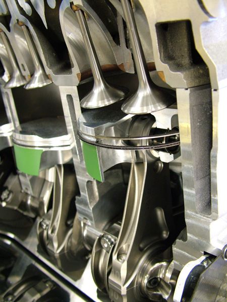
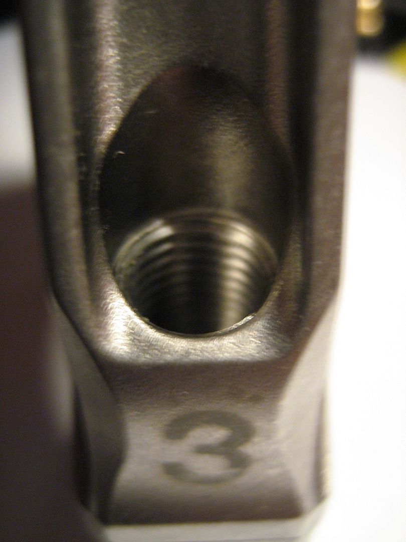
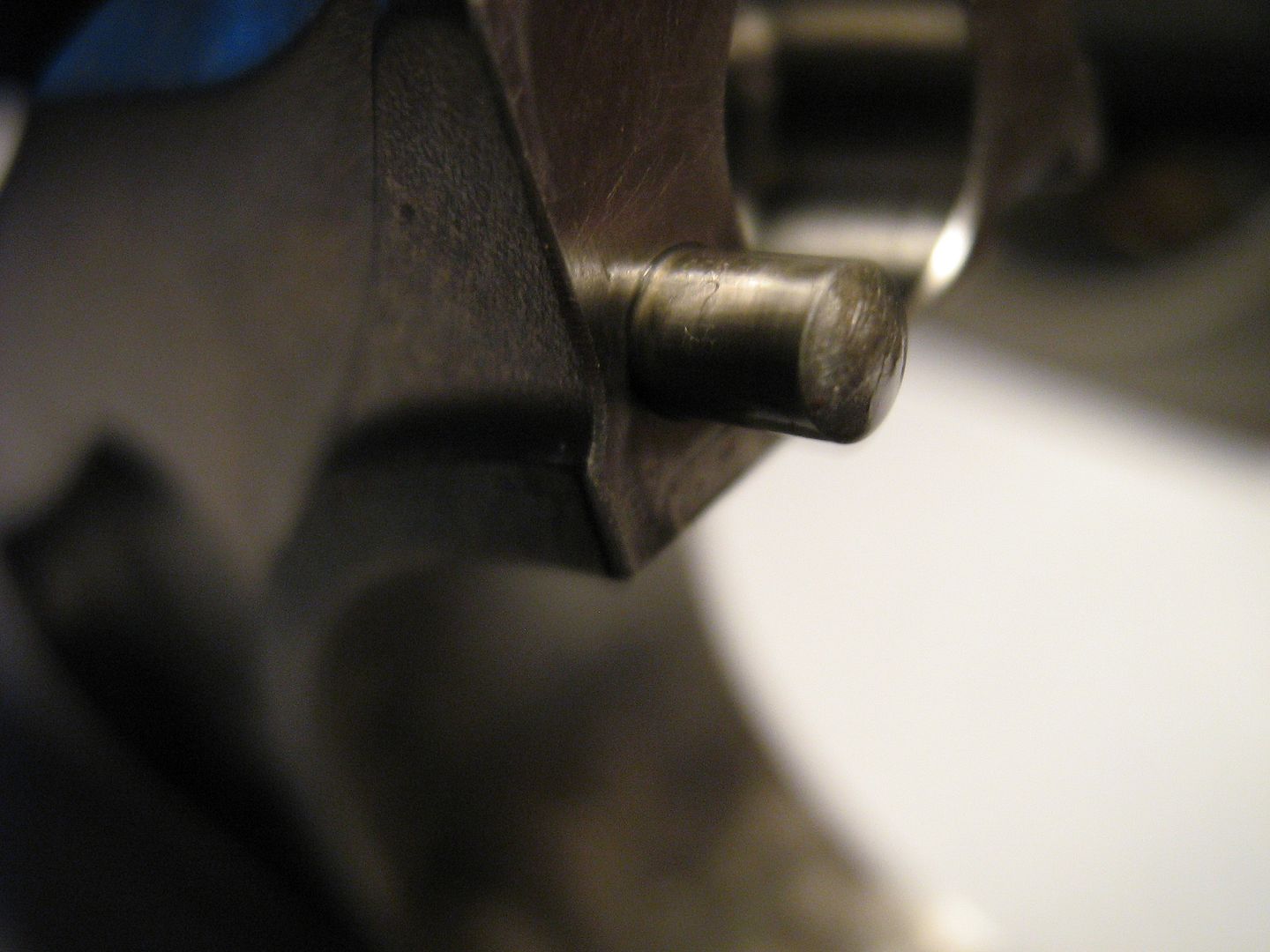
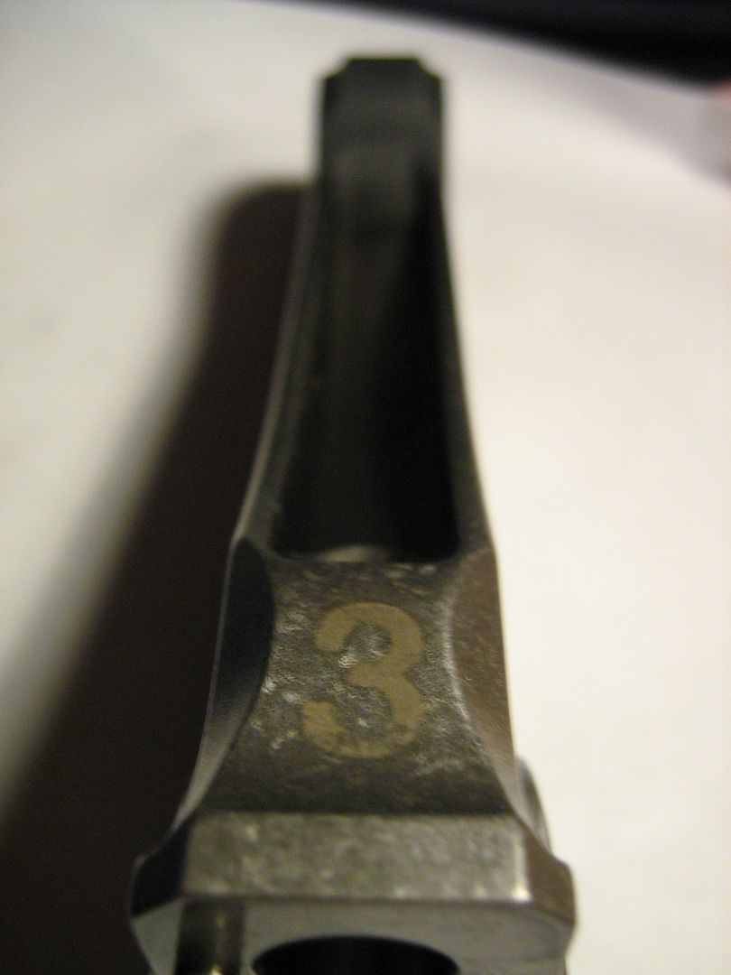
Specification TJ V10 engine produced around 915bhp
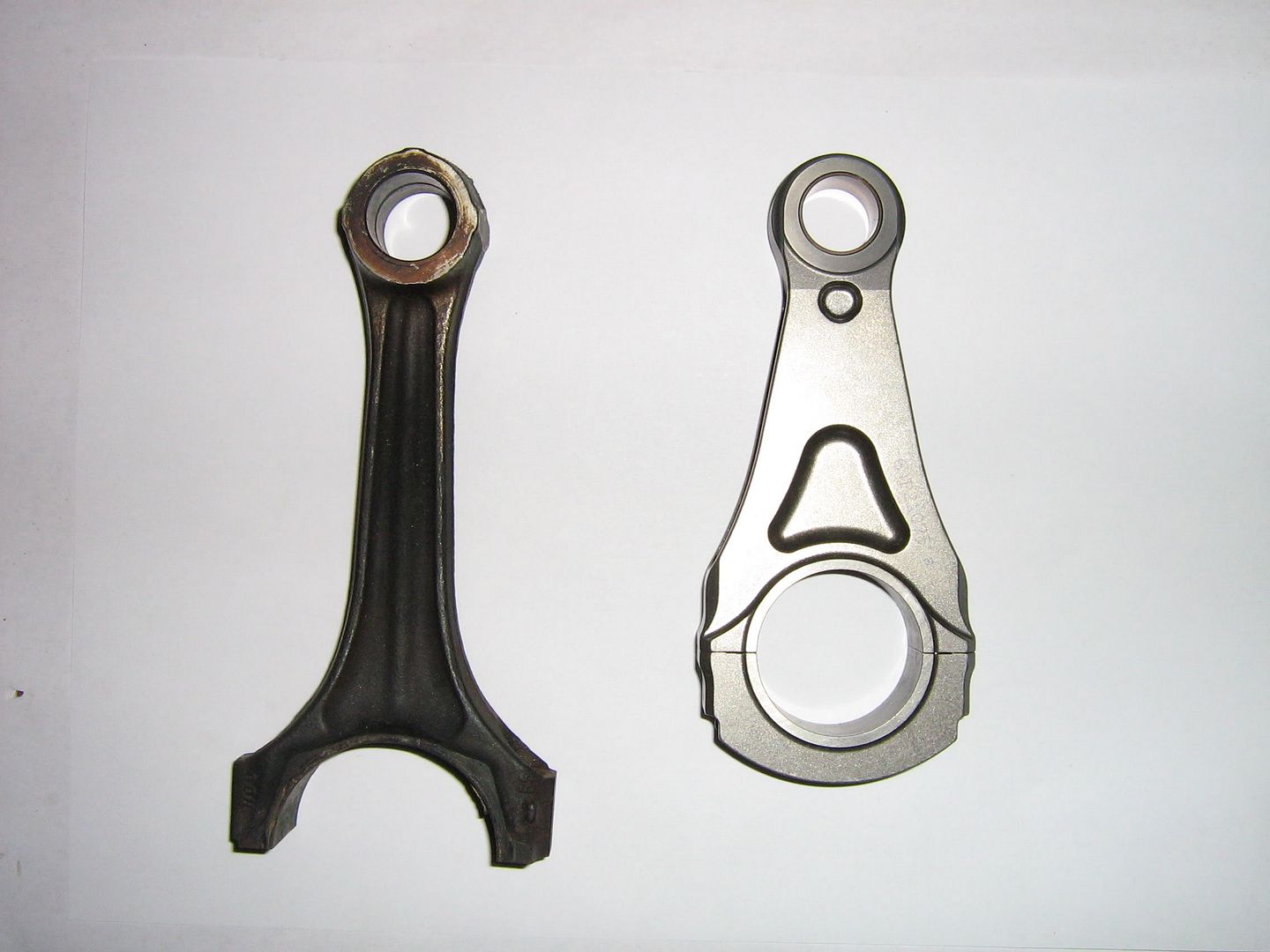
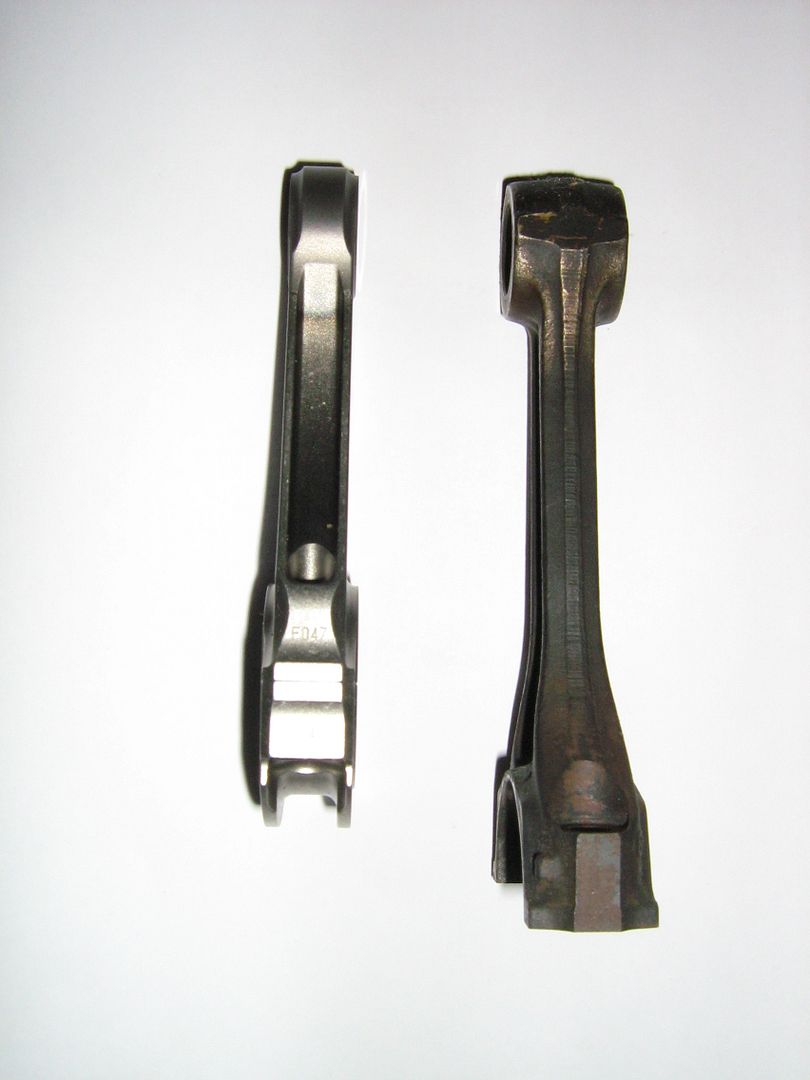
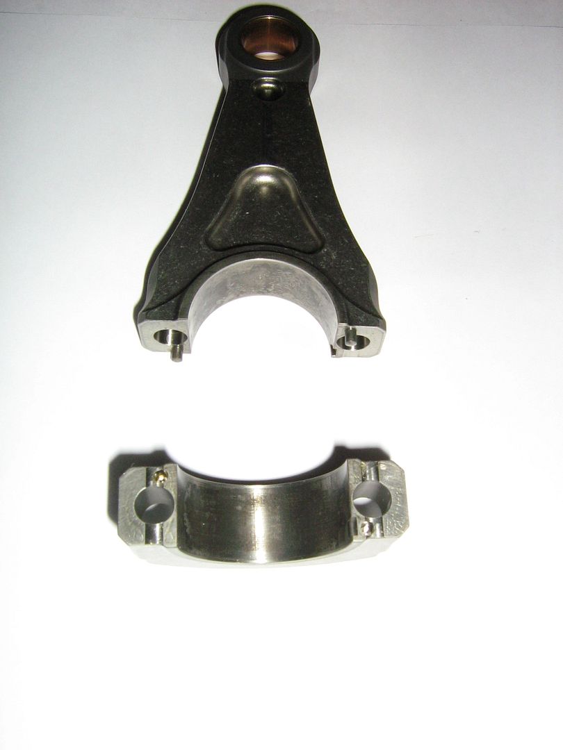
Rod manufacturer> Pankl
Engine it came from show below.
Standard Vw rod shown also for comparison.

Another challenge faced when chasing such high revs were the connecting rod and big end bearings, which displayed their weaknesses very publicly when Nico Rosberg's failed spectacularly in Malaysia. The rods are titanium and, unlike some other manufacturers, still have separate shell bearings. Initially, the rev limit was reduced to ensure the life of the engines while the problem was tackled at the factory. The problem is ensuring the big end adopts the correct shape under load to achieve an even surface pressure across the bearing face with an uninterrupted film of oil. Extensive work on the rod design, bearing specification and choice of engine oil allowed the full 20,000rpm to be built up to again as the season progressed and confidence grew. This is indeed an impressive feat, when you consider that the piston has an equivalent mass of about 2.5 tonnes at 20,000rpm. With peak gas loads greater than 65kN, and peak inertia loads verging on 60kN, there is little wonder the connecting rods can stretch as much as 0.6mm during a single cycle.
Brian Garvey.
Re: F1 pankl conrod
Posted: 13 Jan 2011, 20:24
by Formula None
Good stuff. To our more esteemed members: will the 2013 4 cylinder engine conrods use a similar crankpin to piston dimension?
Re: F1 pankl conrod
Posted: 13 Jan 2011, 20:49
by Brian.G
It hard to say, but Im sure it will be a touch longer for piston skirt to crank weight clearance issues. I suspect they will have to run longer throws when going back to 4 bores just to keep the torque in toe.
It will be interesting in what way they place the engine, that is at what angle to keep the COG low. This, as you know is one of the reasons of using short rods.
There are of course a million other reasons, but that is one.
The V layout was the ideal shape for air ducting under car, and up around engine. The 4 pot will take a lot of work to get the same effect.
Re: F1 pankl conrod
Posted: 13 Jan 2011, 21:19
by malbeare
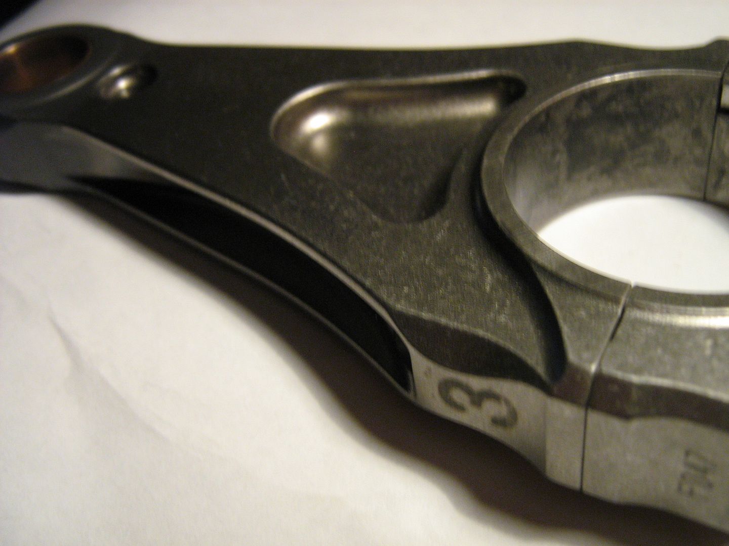
very excellent pics.
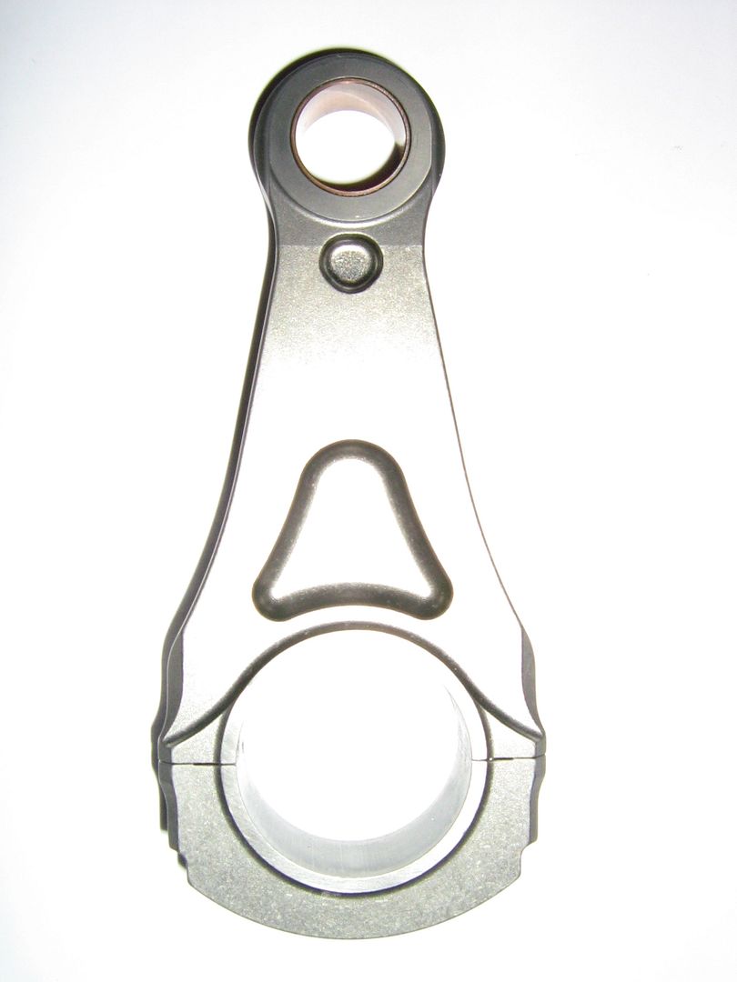
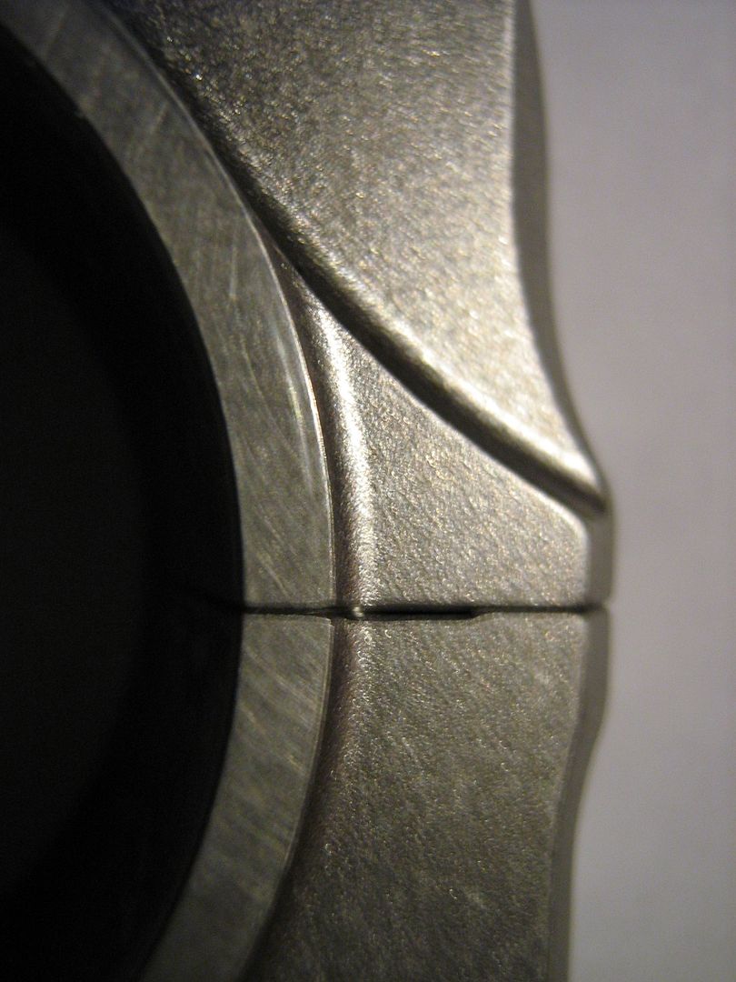
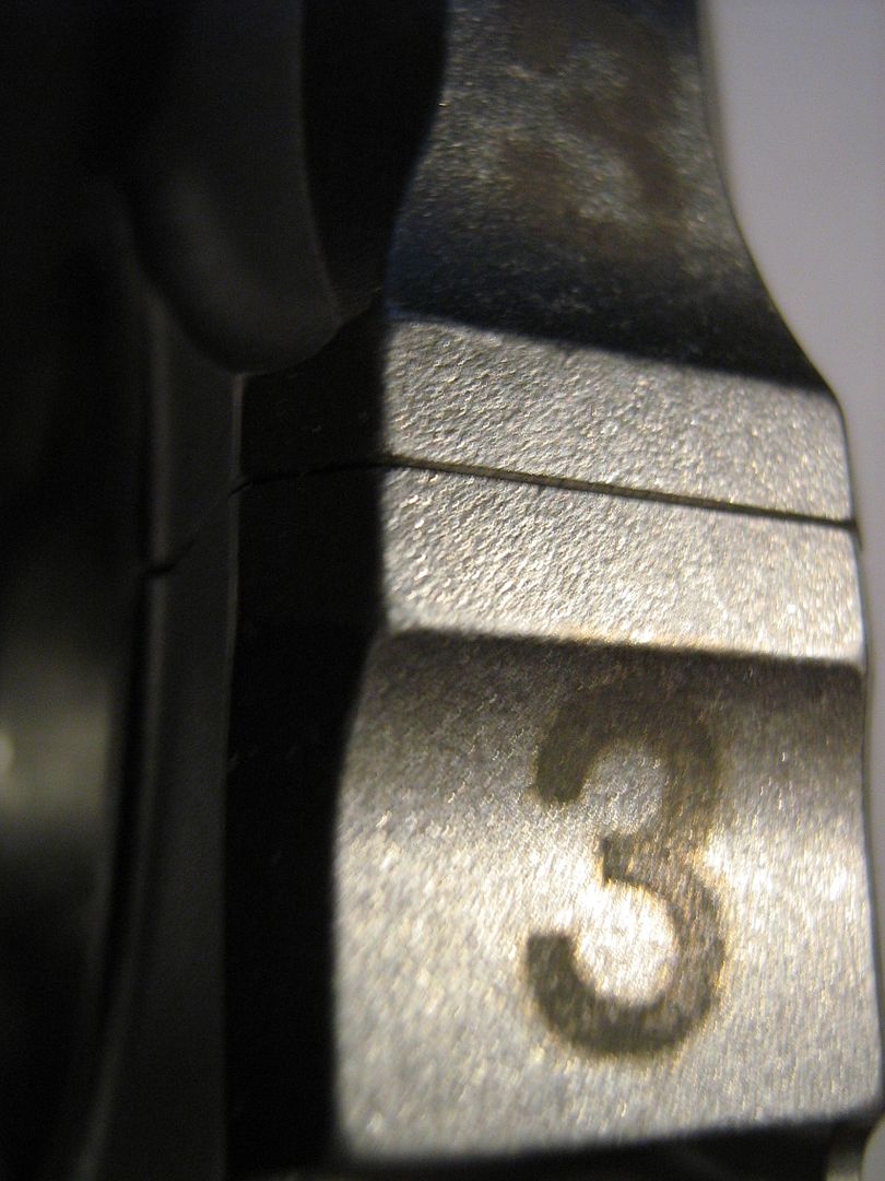
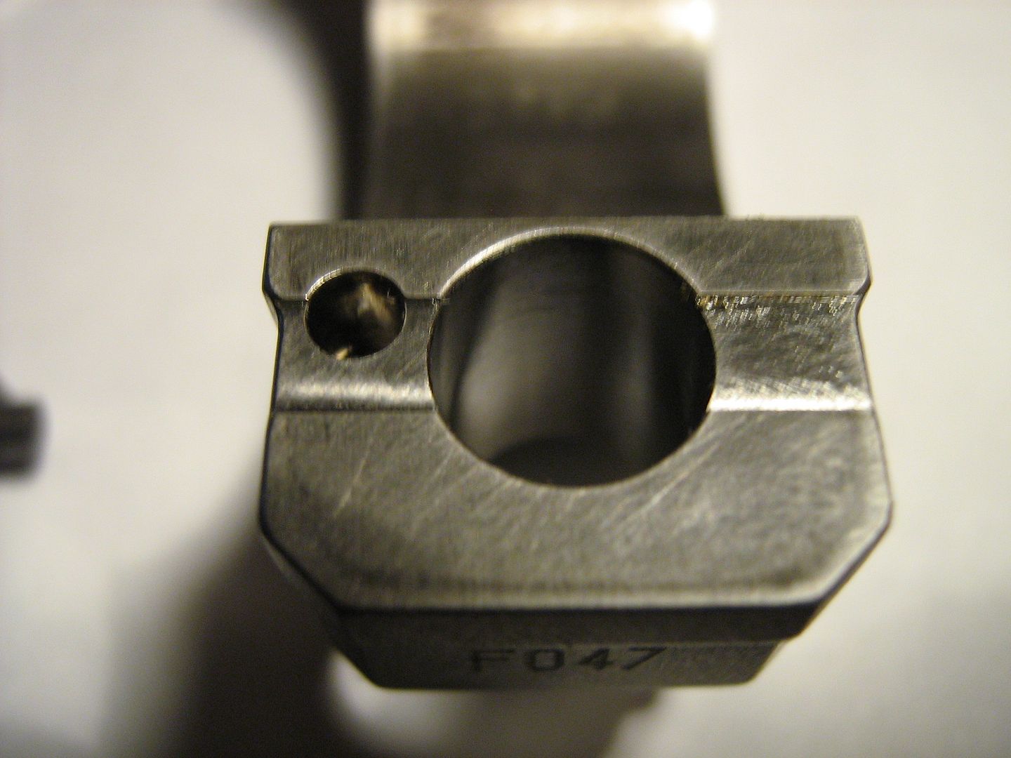
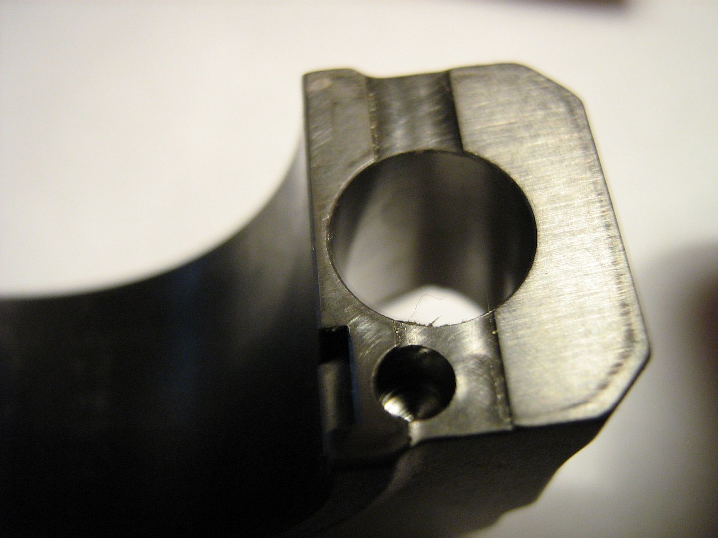
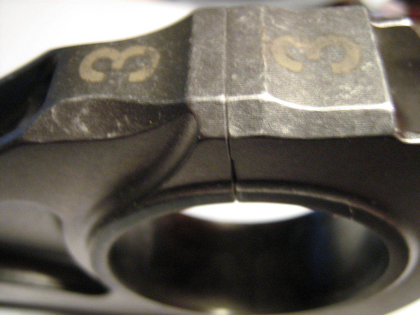
I wonder why the end cap has that groove cut in it acros the bolt hole?
malbeare
Re: F1 pankl conrod
Posted: 13 Jan 2011, 21:33
by Brian.G
malbeare wrote:very excellent pics.
I wonder why the end cap has that groove cut in it across the bolt hole?
malbeare
Im thinking to maximise contact force in those particular areas.
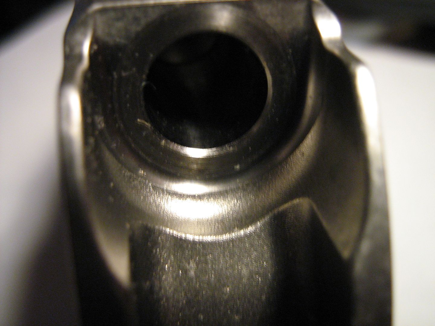
Also Its measuring 38mm across the bore, and 37.82mm from top to bottom.
This is leaving .18mm ovality.
A quick look at the machinery handbook confirms this ovality to be pretty bang on for a ti rod with 38mm as the major diameter to counteract distort under dynamic conditions.
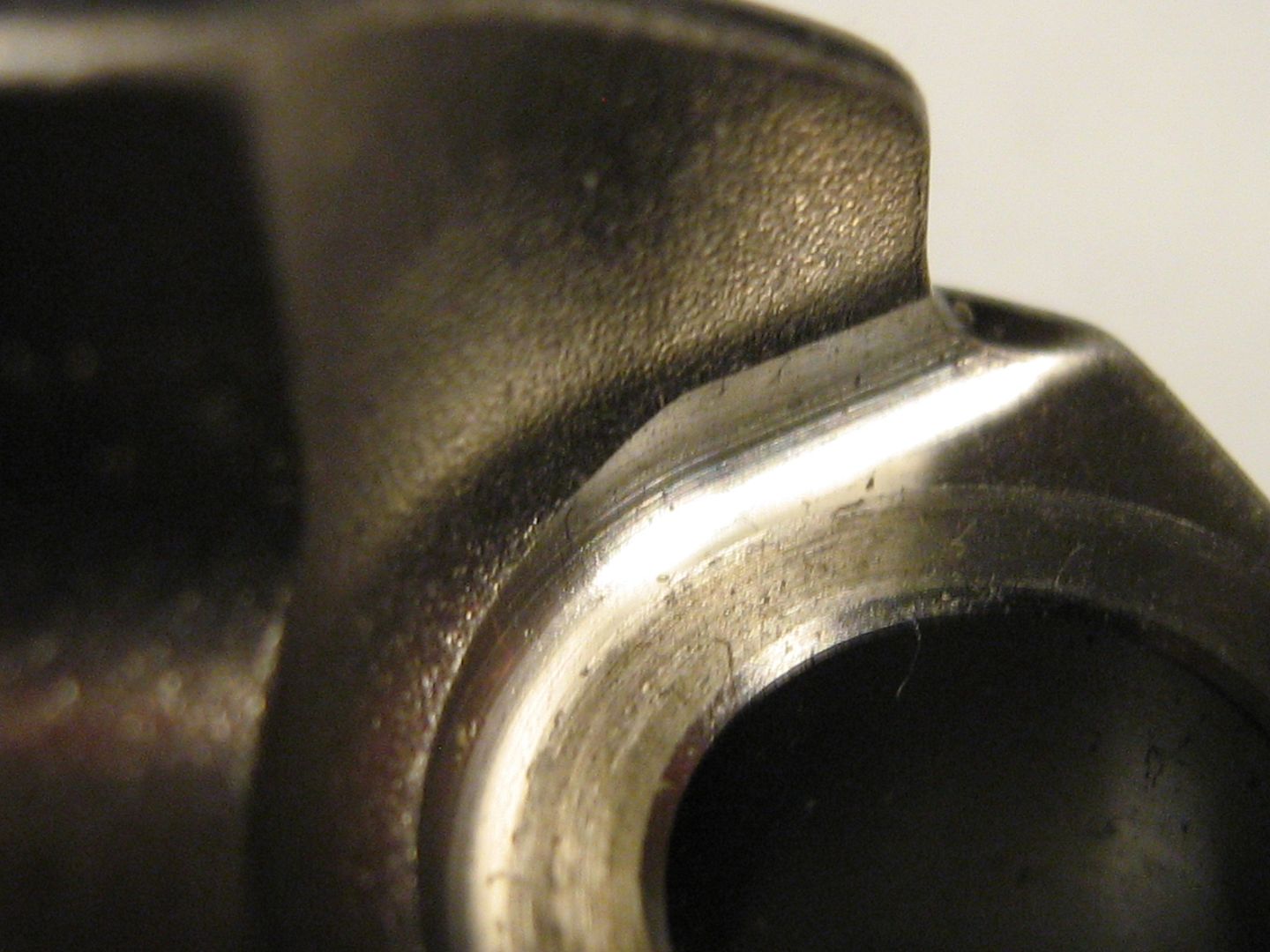
Titanium has a
low(edited miss print) modulus of elasticity in comparison to lets say 4340, a common rod material, so this eccentric, or ovality machining cannot be ignored on a Ti rod. Im sure this is what they have to have done in the case of this engine, but perhaps something the naked eye would not notice, or perhaps be even thought of by just looking at my pictures.
This is another key design feature Im certain, that is important in making an engine last at elevated rpm, and pushing the hp in question.
Brian Garvey
Re: F1 pankl conrod
Posted: 13 Jan 2011, 21:41
by Tim.Wright
Brian.G wrote:
Titanium has a very high modulus of elasticity in comparison to lets say 4340, a common rod material, so this eccentric, or ovality machining cannot be ignored on a Ti rod. Im sure this is what they have to have done in the case of this engine, but perhaps something the naked eye would not notice, or perhaps be even thought of by just looking at my pictures.
The elastic modulus of titanium is actually about half that of steels (like 4340). To my mind, a more compliant material like Ti would require greater ovality because it will deform more than a steel part.
Is that consistent with what you see in the Machinery Handbook?
Tim
Re: F1 pankl conrod
Posted: 13 Jan 2011, 21:47
by Brian.G
Tim.Wright wrote:Brian.G wrote:
Titanium has a very high modulus of elasticity in comparison to lets say 4340, a common rod material, so this eccentric, or ovality machining cannot be ignored on a Ti rod. Im sure this is what they have to have done in the case of this engine, but perhaps something the naked eye would not notice, or perhaps be even thought of by just looking at my pictures.
The elastic modulus of titanium is actually about half that of steels (like 4340). To my mind, a more compliant material like Ti would require greater ovality because it will deform more than a steel part.
Is that consistent with what you see in the Machinery Handbook?
Tim
Isnt that Just what I said Tim?


Re: F1 pankl conrod
Posted: 13 Jan 2011, 21:50
by Tim.Wright
No you said Ti has a higher modulus of elasticity than steel, whereas is actually about half that of steel.
Steel is the stiffer material, not Ti.
Tim
Re: F1 pankl conrod
Posted: 13 Jan 2011, 21:55
by Brian.G
Tim.Wright wrote:No you said Ti has a higher modulus of elasticity than steel, whereas is actually about half that of steel.
Steel is the stiffer material, not Ti.
Tim
God damn, mis print Tim, should read LOW. Im slipping in my old age, tut tut. Its not like me to get my metals mixed hehe!
BG
Re: F1 pankl conrod
Posted: 13 Jan 2011, 22:28
by mep
Brian.G wrote:malbeare wrote:very excellent pics.
I wonder why the end cap has that groove cut in it across the bolt hole?
malbeare
Im thinking to maximise contact force in those particular areas.
And what is it good for?
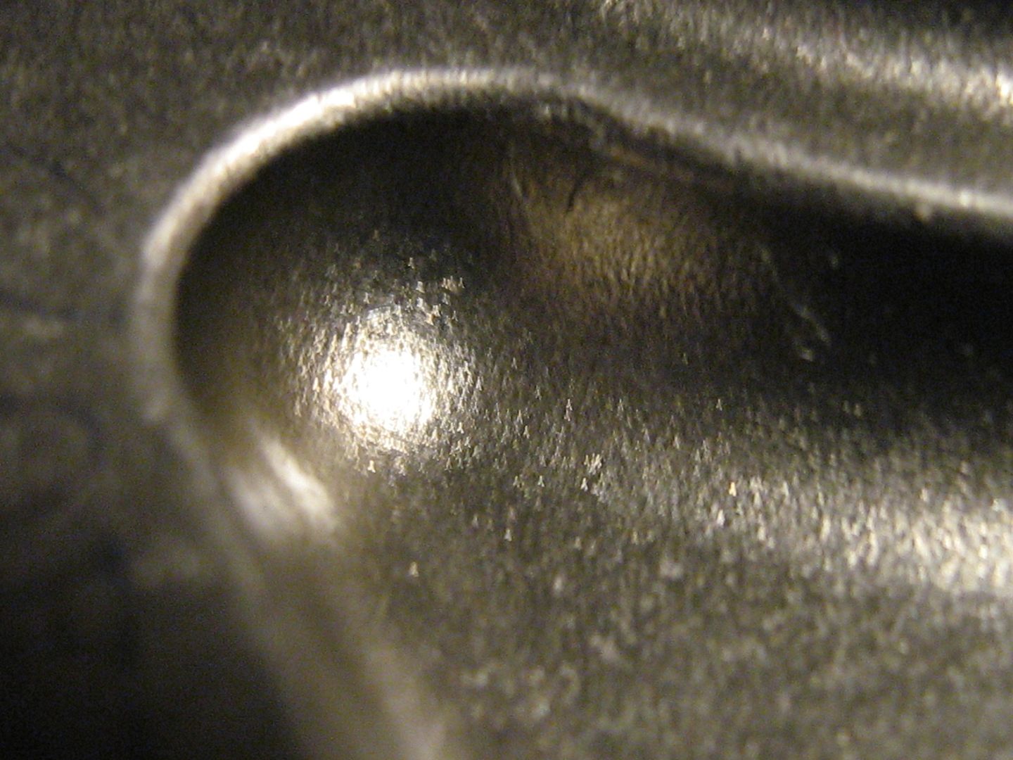
It's noticeable that there is a ring around the bore and that the cut
keeps the ring thickness constant on this place but then there should also be such a cut on the upper half.
It's one of the million little mysteries of engineering.
Re: F1 pankl conrod
Posted: 13 Jan 2011, 23:02
by Brian.G
Groove just on cap.
I would Imagine by making a groove, the clamping force is made greater on the inner and outer contact patches, cutting down on cap walk, and thus keeping it rounder.
BG
Re: F1 pankl conrod
Posted: 13 Jan 2011, 23:43
by mep
hmm ok I just keep on thinking little bit on this and write down what I get into my mind....
The cut is on the lower half. It increases the pressure in contact zone and should therefore increase deformation of the lower part when you put in the screws. There are two load cases for the connection rod.
1. The piston pushes down, con rod is in compression.
2. The piston gets pulled down, con rod is in tension
The second case is important for the lower semi shell because it gets stretched in the area where the cut is. Now this area with reduced cross-section is already compressed by the screw initial load. The two loads act against each other reducing the pressure in the smaller are and causing the hole to get into its perfect round shape during that load case.
That's my guess about it.
Re: F1 pankl conrod
Posted: 13 Jan 2011, 23:54
by Brian.G
mep wrote:hmm ok I just keep on thinking little bit on this and write down what I get into my mind....
The cut is on the lower half. It increases the pressure in contact zone and should therefore increase deformation of the lower part when you put in the screws. There are two load cases for the connection rod.
1. The piston pushes down, con rod is in compression.
2. The piston gets pulled down, con rod is in tension
The second case is important for the lower semi shell because it gets stretched in the area where the cut is. Now this area with reduced cross-section is already compressed by the screw initial load. The two loads act against each other reducing the pressure in the smaller are and causing the hole to get into its perfect round shape during that load case.
That's my guess about it.
Sounds right to me?
Re: F1 pankl conrod
Posted: 14 Jan 2011, 21:24
by malbeare
does the bearing shell have the same ovality of the conrod in the big end when installed? If so then would this mean that the bearing clearence is 0 at the top and bottom when the engine is not running? would it be neccessary to have a very high idle (say 5000) when running to keep the dynamic forces in play to keep the big end round when running ?
Re: F1 pankl conrod
Posted: 14 Jan 2011, 23:43
by Brian.G
malbeare wrote:does the bearing shell have the same ovality of the conrod in the big end when installed? If so then would this mean that the bearing clearence is 0 at the top and bottom when the engine is not running? would it be neccessary to have a very high idle (say 5000) when running to keep the dynamic forces in play to keep the big end round when running ?
I dont know the full details, but yes, the oil film thickness is reduced top and bottom when not running. Thats why the oil is preheated/etc.