Formula One engines
Although F1 racing engines have lost some of the attractiveness they used to have when the regulations allowed more freedom, every single design currently in use is still a highly advanced piece of engineering that has required lots of time and thought. An engine is the only power source of a Formula One car - apart from the KERS systems in 2009 which are indirectly charged by the power generated by the engine - and is a structural part of the chassis.
Facts and figures
 Because of the regulations and engineering optimisations, all current engines are of a similar type, and feature the following similarities:
- All F1 engines are naturally aspirated V8's of 2400cc
- Engines are limited to 18,000rpm
- The weight is exactly 95kg (each manufacturer easily reaches this regulated minimum weight)
- Engine blocks are constructed of forged aluminium alloy, because of the weight advantages it gives in comparison to steel. Other materials would maybe give some extra advantages, but to limit costs, the FIA has forbidden all non-ferro materials.
- Crankshaft and piston rods are Iron based for strength.
- At its maximum pace the current V8 engines consume around 60 litres of petrol for 100km of racing.
- It's not exactly known how much oil such a top engine contains, but this oil is for 70% in the engine, while the other 30% is in a dry-sump lubrication system that changes oil within the engine three to four times a minute.
- Before its first track time and after each race, each engine is tested on an engine dyno to validate its performance and identify problems. A video clip of Renault's RS24 on the dyno can be found here.
Evolution of engine design
All current engines run by the competing F1 teams are very similar due to the very stringent regulations that have increasingly come into play since 2006. Until that time, all car manufacturers involved in F1 were effectively out-racing each other in a spending race. It is not a lie to claim that in the years after 1995, the manufacturer who invested most and could hire most people could produce the best engine.
Back in 1997, Ford Cosworth started a furious battle for weight reduction as their CR1 at the time was at least 25kg lighter than any other. 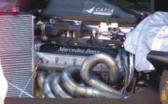 Although they suffered some reliability problems throughout the season, the engine was an example for the others, as it allowed the team to shift ballast in the car to benefit the car's handling.
As a reaction to this weight shedding, the the 1998 Mercedes-Benz engine was possibly one of the most revolutionary engines ever built, making performance gains and drastic weight cuts at the same time. It quickly proved good enough to be the basis of Mika Hakkinen's two consecutive world titles with McLaren Mercedes. When in 2000, the FIA decided to limit the use of Beryllium alloys - to a maximum of 5 mass percentage - due to being poisonous in high quantities, Mercedes struggled for years to recover from that setback - they could not match any more the power of the at that time mighty Ferrari and BMW engines.
By the end of 2005, most of the teams had converged their designs to 3 litre V10's with an internal angle of 90°. The teams' designers had come to the conclusion that 90° was the best compromise between performance and stiffness of the engine itself.
That same year, some 3l V10 engines were producing more than 980hp and running very close to the 1000hp mark, a figure that was never reached since the ban on turbo engines. It was a sign for F1's governing body to change the regulations as top speeds at Monza of 370km/h were deemed hazardous for the drivers as well as the spectators. The maximum capacity was thus reduced to 2.4l and the cylinder count to 8. Additionally, the FIA ruled that an engine freeze would come into effect a year later to put an end to the spending race.
Only 2 years later however, halfway through 2008, the FIA and several teams who strictly followed the rules - including the likes of Toyota and Renault - found that the regulations still allowed too much freedom. It appeared that over the last year, Mercedes and Ferrari had been able to add up to 40hp to their engines as so called "reliability updates", while others had followed the engine freeze more strictly. Several meetings with FIA officials and the teams' principals then resulted in an equalisation of the engines, in which the less powerful could put on several updates to be on par in the next years.
Even so, without fiercely looking for improvements, a current F1 engine is a highly interesting piece of engineering, in total consisting of 5000 separate parts, 1500 of which are moving. It is estimated that when in operation, a new F1 engine can produce around 720hp, but would be able to reach up to 780hp and above 20,000rpm if there would not be a limit on engine revolutions.
Difference with road engines
- Higher volumetric efficiency. VE is used to describe the amount of fuel/air in the cylinder in relation to regular atmospheric air. If the cylinder is filled with fuel/air at atmospheric pressure, then the engine is said to have 100% volumetric efficiency. Turbo chargers for instance can increase VE to above 100% while normally aspirated engines typically run anywhere between 80% and 100%. In this region however, a Formula One engine usually can achieve a higher VE than normal road engines because of their highly optimised intake manifolds.
- Unfortunately, from the total fuel energy that is put into the cylinders, averagely less than 1/3 ends up as usable horsepower. Ignition timing, thermal coatings, plug location and chamber design all affect the thermal efficiency (TE). Low compression street engines may have a TE of approximately 0.26, a racing engine may reach approximately 0.34. This seemingly small difference results in a difference of about 30% (0.34 - 0.26 / 0.26) more horsepower than before.
- From all that power generated, part of it is used by the engine to run itself. The left over power is what you would measure on a dynamometer. The difference between what you would measure on the dyno and the workable power in the cylinder is the mechanical efficiency (ME). Mechanical efficiency is affected by rocker friction, bearing friction, piston skirt area, and other moving parts, but it is also dependent on the engine's RPM. The greater the RPM, the more power it takes to turn the engine. This means limiting internal engine friction can generate a large surplus in power output, and where in F1 the stress is on power, on the road it is also on fuel consumption.
These main optimization necessities are what makes Formula One engine design difficult. At the end of the line, an F1 engine revs much higher than road units, hence limiting the lifetime of such a power source. It is especially the mechanical efficiency that causes Formula One engines to be made of different materials. These are necessary to decrease internal friction and the overall weight of the engine, but more importantly, limit the weight of internal parts, e.g. of the valves, which should be as light as possible to allow incredibly fast movement of more than 300 movements up and down a second (this at 18.000 rpm).
Another deciding point trying to reach a maximum of power out of an engine is the exhaust. The minor change of length or form of an exhaust can influence the horsepower drastically. Although variable outlet systems are not allowed, the exhaust system on a race car does not feature a muffler, lacks a katalysator and is specially made to withstand temperatures as high as 1200°C, a lot more than what is achieved with a regular road engine.
Engine design philosophies
Considering internal combustion engines (thus leaving out oscillating and Wankel rotary combustion engines), there are basically three different ways of building an engine. The difference here is how the cylinders are placed compared to each other.
- Inline engines, where all cylinders are placed next to (or after) each other are not used in Formula One since the 60's. While the engines are small, they are long and therefore require a heavy crankshaft.
- Boxer engines are actually one of the best ways to build an engine, if all external factors allow it. Two cylinder rows are placed opposed to each other. You could consider a boxer engine as being a 180° V-angle engine design. These engines became popular in F1 because of the low centre of gravity and the average production costs, but later on disappeared out of the picture as this type of engine is not sufficiently stiff enough to withstand the car's G-forces in cornering conditions. Ferrari for instance have run 12 cylinder boxer engines from 1970 to 1980 before moving to a 120° V-angle engine.
- V-type engines, as currently used in all F1 cars. The V is in fact the geometrical angle that separated the two cylinder banks from each other where the crankshaft can be considered the origin of the angle. Obviously for this type of engine the size of the V is a major factor and must be decided in the first phases of the engine design. Previously, engines have been designed with angles such as 60° V12 or 72° V10. Although it has historically been an interesting evolution to see the differences between the teams' engines, the FIA have fixed the engine type to 90° V8 models.
Since the introduction of the Ford Cosworth DFV, an engine in a F1 car is a stressed member of the chassis, meaning that it is an integral part of the car. Before that idea, a chassis was built as a tube frame with the engine placed in it afterwards, while now a chassis would fall apart if no engine was fitted. A current engine is bolted in between the rear end of the monocoque and the frontal side of the gearbox. As of that time, V-type engines have gradually pushed out any other engine type because they are compact and can be constructed very rigidly without requiring further strengthening to the chassis to ensure stiffness.
Contrary to boxer or flat engines, V-angled combustion engines pose an extra design problem, as it is crucial for an engine's performance that the V-angle is chosen wisely. This angle important to ensure a correct firing sequence and hence also influences its primary balance.
Calculating possible V angles for a specific number of cylinders is fortunately not a daunting task. If you consider that every combustion cycle takes 2 turns - intake and combustion phase - of the crankshaft, and a full circle is 360°, the engine's included V-angle x the number of cylinders must be a function of 720 in order to achieve evenly spaced cylinder firing and primary balance.
That is also why a boxer engine is an ideal layout. The cylinders are opposed at 180° so having 2 or 4 or 6 or 8 or 10 or 12 isn't that big. Perfect primary balance is easy to achieve, as long as the reciprocating and rotating parts are in balance and, the firing order is always evenly spaced. A few examples make it clear why several specific angles have been very popular in F1 engine design:
- As mentioned earlier, Ferrari have used a 60° V12 or 120° V12 engine. As for the first option, divide 720° by 12 cylinders and you get 60. You get 120° when you imagine a V12 as two aligned V6 engines.
- Renault's extremely successful 72° V10 engines share the same thoughts. It is the perfect bank angle for any V10 engine if a boxer is not an option. One cylinder is fired every time the crankshaft has completed 72° so that after 2 turns every single piston has gone through one complete cycle.
- Currently every team runs 90° V8 engines but not only because the regulations prescribe so. Also this is a perfect angle and meets the size requirements set by the aerodynamicists.
 Contrary to these optimal choices, there have also been unusual uses. For instance the 2005 90° V10 engines that everyone but Renault were using. While they may have been more interesting for other reasons, it's performance could theoretically not beat Renault's RS25 that was a 72° V10. The 90° V10 engines hence had either offset crank pins or a funny firing order.
- Before their RS24 Renault was trying a revolutionary design as they designed a 112° V10. Although the engine evolved from RS21 to RS23 and was beneficial in terms of the centre of gravity it was finally abandoned. The engine could not reach competitively high rpms since the uneven firing order introduced unwanted vibrations in the engine.
 Contrary to these optimal choices, there have also been unusual uses. For instance the 2005 90° V10 engines that everyone but Renault were using. While they may have been more interesting for other reasons, it's performance could theoretically not beat Renault's RS25 that was a 72° V10. The 90° V10 engines hence had either offset crank pins or a funny firing order.
Crankshaft design
Although the V8 with the now compulsory cylinder angle of 90 degrees may look like a sawn-off V10, technically it is an entirely separate concept with its own specific requirements. The V8 has a distinct firing sequence and demands a fundamentally different crankshaft design. Whereas a 72-degree offset crankshaft was used in most V10 Formula One engines, V8 powerplants can feature crankshafts with either four throws spaced at 90 degrees or four throws spaced at 180 degrees. Standard production engines are fitted with 90-degree crankshaft variants due to their better dynamic attributes, but a 180-degree crankshaft is favoured in racing car engine design. The improved performance this allows offsets the disadvantages in terms of dynamics.
Cooling
With such a low thermal efficiency, cooling of any internal combustion engine is vital for its correct operation. Basically, an F1 cooling system is the same as in any regular road car, as engine coolant and oil is pumped through a radiator to cool down before completing another cycle through the engine.
However, due to the space restrictions and aerodynamic requirements of a race car, the positioning of these components is completely different. The following shows the internals of a championship winning Renault R25 of 2005, included with its Renault RS25 engine (2). The flat panels located nearly vertically in the front of the side pods are the radiators (4). While in this picture the radiator is covered with a protective hose, it is not during running as air passes through the aluminium fins of the radiator. Their position however varies considerably in different cars as they are influenced by the aerodynamic and weight distribution requirements of a car.
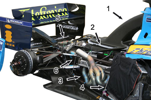
Contrary to popular belief, the air inlet above the driver's head is not part of the cooling system but instead provided the engine's cylinders with air to be mixed with fuel for combustion. It is commonly thought that the purpose of this is to 'ram' air into the engine like a supercharger, but the airbox does the opposite. The carbon fibre duct (1) gradually widens out as it approaches the engine, effectively creating a venturi and a suction effect on the small air inlet. The shape of this ducts and inlet however must be carefully designed to both fill all cylinders equally and not harm the exterior aerodynamics of the engine cover, all to optimize the volumetric efficiency.
Marked with (3) is the engine exhaust system while (5) and (6) identify the rear suspension that is fitted onto the gearbox.
Transmission
The transmission of any car is considered to be all intermediate gears and systems to get the engine rotational power to the wheels. In reality this comes down to the gearbox and differential, which are both assembled into the gearbox casing. Just as with the engine, this casing - often made of titanium or carbon fibre - is also a structural part of the chassis and is firmly bolted onto the rear end of the engine. More can be found in the specific article about F1 transmissions.
Regulations
The current regulations on Formula One engines can be summarised as follows. These specifications have become more strict during recent years in an attempt to limit costs and decrease performance. You can find an evolution of the most important regulations per era in the safety section. As this is only an excerpt of the most important regulations on engines, you would need to see the official FIA technical regulations before you start to design a Formula One engine yourself.
Only 4-stroke engines with reciprocating pistons are permitted.
Engine capacity must not exceed 2400 cc.
Crankshaft rotational speed must not exceed 18,000rpm.
Supercharging is forbidden.
All engines must have 8 cylinders arranged in a 90 degree V configuration and the normal section of each cylinder must be circular.
Engines must have two inlet and two exhaust valves per cylinder.
Only reciprocating poppet valves are permitted.
The sealing interface between the moving valve component and the stationary engine component must be circular.
Cylinder bore diameter may not exceed 98mm.
Cylinder spacing must be fixed at 106.5mm (+/- 0.2mm).
The crankshaft centreline must not be less than 58mm above the reference plane.
The overall weight of the engine must be a minimum of 95kg.
The centre of gravity of the engine may not lie less than 165mm above the reference plane.
The longitudinal and lateral position of the centre of gravity of the engine must fall within a region that is the geometric centre of the engine, +/- 50mm. The geometric centre of the engine in a lateral sense will be considered to lie on the centre of the crankshaft and at the mid point between the centres of the forward and rear most cylinder bores longitudinally.
Variable geometry systems are not permitted
Magnesium based alloys, Metal Matrix Composites (MMCs) and inter-metallic materials may not be used anywhere in an engine
Coatings are free provided the total coating thickness does not exceed 25% of the section thickness of the underlying base material in all axes. In all cases the relevant coating must not exceed 0.8mm.
Pistons must be manufactured from an aluminium alloy which is either Al-Si ; Al-Cu ; Al-Mg or Al-Zn based.
Piston pins, crankshafts and camshafts must be manufactured from an iron based alloy and must be machined from a single piece of material.
A supplementary device temporarily connected to the car may be used to start the engine both on the grid and in the pits.