And if there are significant advantages what should determine a limit to the length of a set of control arms?
thanks


exactlyJersey Tom wrote:Absolute control arm length actually does not do much for your camber curves. You can have 0 deg / inch bump camber with 4" long control arms. Camber curves are all about relative length and non-parallelism.
Control arm length does however really help scrub. Lateral motion of the tire through bump travel will give rise to changes in slip angle.. the significance of which you'll have to determine.

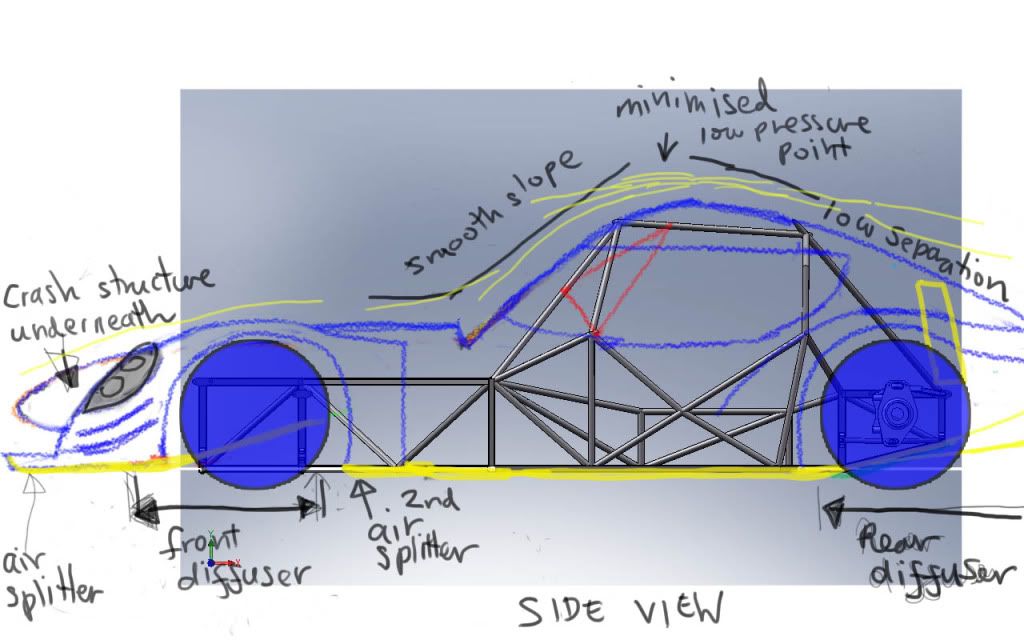
I had an option to integrate a plate structure behind it to hold the wing and rear bumper that will double as a reinforcement. But after looking at it I will move it to the left onto the top long. beam.That damper mount will probably either twist the tube or shear right off.
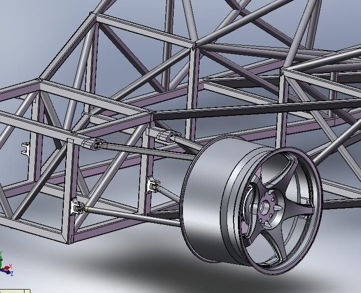
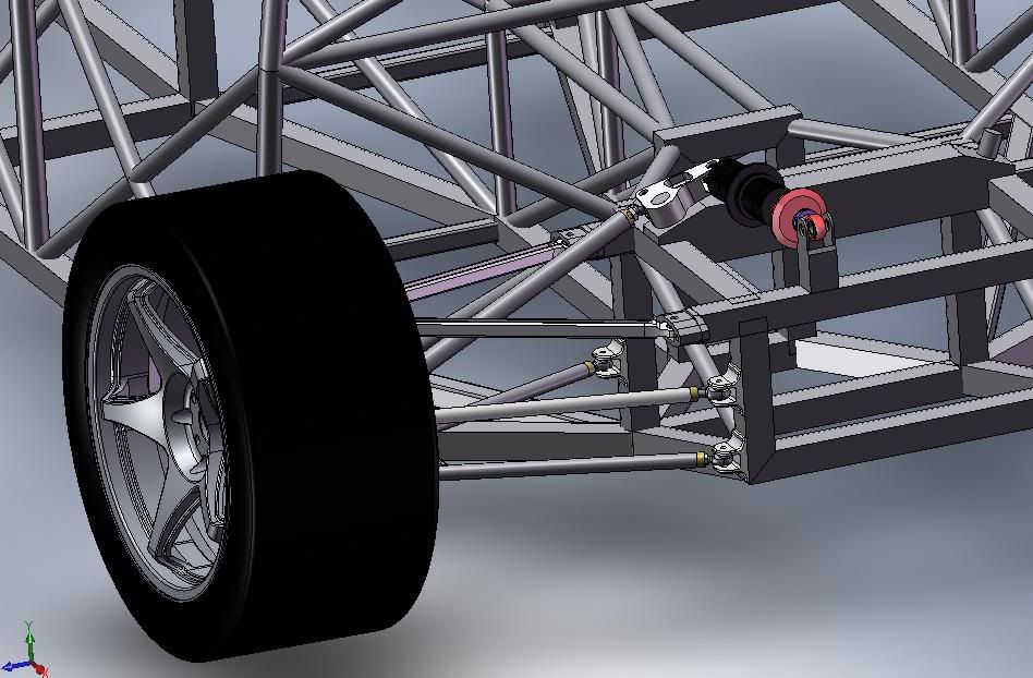
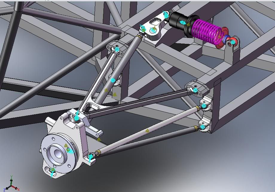
The top aluminum A arms, were mostly done for the hell of it. But I have seen them used on some Race cars before. It's about 2/3 lighter even with the bearings. If it were to be actually built though i would use the steel though.Why the weird billet a-arms?
This is just for the simulation, the model would not calculate properly when i used the radius bends. The steel angles were strong enough though.Or the chassis tubes / roll hoops with sharp angles instead of nice bent radii?
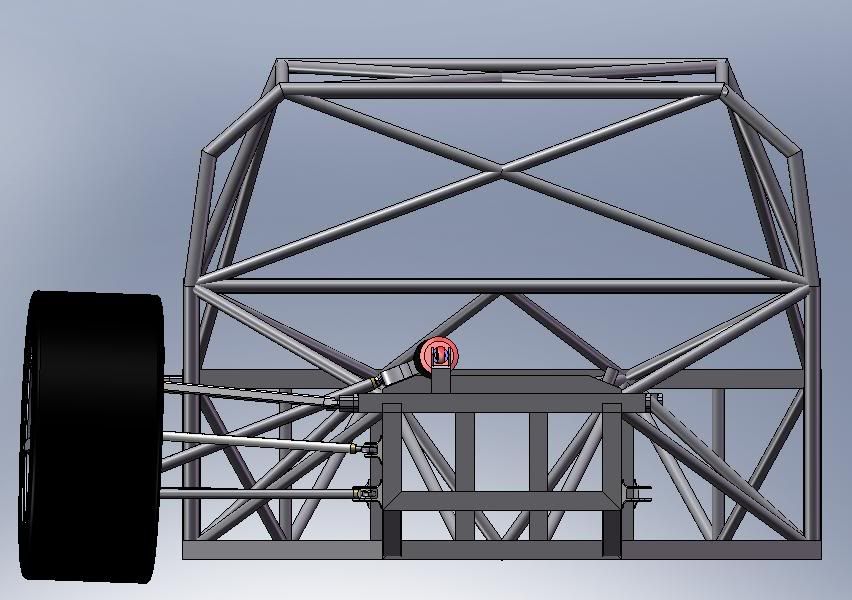
I thought about that. The whole bell crank, push-rod and shocks are in a single plane, so when the suspension moves all the loads are in that plane just as if it were arranged in a vertical position. The effort was also made to put the line of action of the push-rod and shock close to a tangent around the bell crank. I have to post a picture of how I did it. Additionally i will get a picture of the reaction force vectors from the motion simulation to show you. (just the directions, not the magnitude because the proper forces were not put in yet)why do you put them this way ? your bellcrank bearings fill face a lot of thrust load in extreme bump-droop positions and of course you will not direct all forces into the damper spring this way