They certainly seem to be wanting less air going through there.horse wrote:Perhaps they use the sensors mounted at the top of the car for static pressure?SZ wrote:Actually, on second thoughts is that rake pitot-static? I can only see one pressure tube out of the rake per position, unless the static channel is mounted on a common manifold.
EDIT: God, Jenson still looks really high in the car! And whatever that extra channel does, McLaren don't seem to want it doing it any more...
Thanks to Scarbs for some real infromation!meves wrote:I've zoomed in a little, but it hasn't helped me!
Also they've changed the cooling at the rearThey've closed off the oil cooler inlet in the roll hoop
McLaren: they are also playing with the cooling outlets, note the openings on the engine cover
There is something very odd about the way it retains its volume, especially when you see Merc with their incy wincy tiny airbox, with a fin to make up the required height dimensions. So why do McL have the bulk in theirs? Maybe it is just a bit of slipstream styling, but you'd think they want it with least bodywork volume to maximise air volume hitting the the wing?CMSMJ1 wrote:Related to this....unless someone shows some pictures of the ducting, flappery or mumbo jumbo involved then it is wild speculation.
...
You guys are clever enough
Looks the same as Valencia test to me. Only thing I can spot is they have lost the small vents below the head protection, not engine covermeves wrote: Thanks to Scarbs for some real infromation!
Before you get too loved up with Scarbs...Think he may also have some duff information
McLaren: they are also playing with the cooling outlets, note the openings on the engine cover
First idea more feasible.Spencifer_Murphy wrote:SZ, is there anyway that any flow coming from a possbile duct in the sharkfin could (even allowing for the pipe losses) be used to activly try and break up the boundary layer, kinda like the dimples in a golf ball?
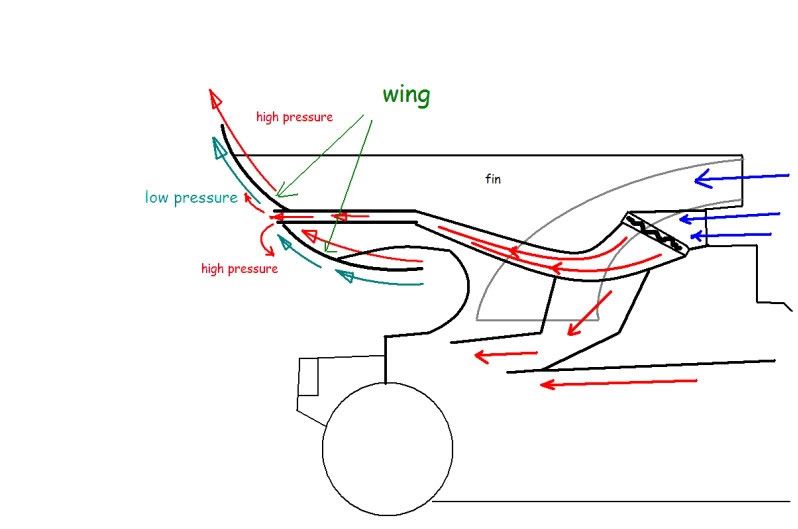
Also, is it possible that, the duct itself could in fact be a converging duct, raising the static pressure and the mass flow rate of the air in order to counteract the pipe losses when it eventually vents out of the fin to the underside of the wing?
Just a thought, it could be total tosh lol.
yeah i've been playing spot the difference and i see nonemeves wrote: Thanks to Scarbs for some real infromation!
Also they've changed the cooling at the rearThey've closed off the oil cooler inlet in the roll hoop
McLaren: they are also playing with the cooling outlets, note the openings on the engine cover
So I suspect that it isn't the oil cooler that McLaren are experimenting with today, but rather the flow to the wing.Pup wrote:If the whole "blown flap" theory is true, then I suspect that the topmost section is ducting through the fin into the wing, where it's then released via what looks like a small slit that runs across the back, near the leading edge.
Some of us were talking about this via PM's - my thinking now is that the flow of air would be continuous, without any sort of control other than the speed of the car. At lower speeds, the airflow acts just like a blown flap would on a plane, allowing a steeper angle for the wing without the boundary layer separating and stalling. But then at high speeds, the effect of the blown flap is overcome and the wing then stalls. The point at which that happens could be adjusted then for each circuit as needed by limiting the maximum flow of air to the wing slots.
Of course, I don't know if physics really works that way, but it sounds good to me.
Checkered sent me these links, which are pretty interesting...
http://en.wikipedia.org/wiki/Blown_flap
http://www.tu-braunschweig.de/Medien-DB ... ngsten.pdf
...and this one, which made me laugh since I'd never have put the two together...
http://www.dyson.com/fans/
This comes from Wiki:Circulation Control Wing which seems to quite the reverse of what is suggested above.richard_leeds wrote:The potential of the duct feeding into the rear wings was disussed a couple of weeks ago, around page 40
viewtopic.php?f=12&t=7495&hilit=duct&start=585
We'd also spotted a thin slit in the rear face of the wing that could be used to bleed air out of the duct. You can clearly see this in the flow vis pic, note how the two element wing appears to have 3 elements when teh flow vis gets to work ...
Then on page 41, Ringo came up with this summary...
ringo wrote:The fin putting air on the wing wont be of much help. The air wont be a better quality of the free stream air. Stalling is also not desirable at any rate, the wing would behave like a bluff body only creating drag.
The air through the heat exchangers is not steady either and it loses most of the KE hitting into the grating of the exchangers.
What could work however, is if air was injected behind the wing, between the wing elments though a duct in the fin. This air would have to be at a higher pressure than that on the low pressure side of the wing. Introducing high pressure behind the wing would reduce the pressure difference between the sides of the wing, reducing drag and reducing lift. This only works if the enthalpy gained by the air going through the heat exchangers can restore most of the pressure and energy lost.
For it to work the injected pressure has to be higher than that behind the wing. the closer it is to free stream pressure the better. With equal pressure on both sides, ideally the wing would behave as if it was not there, no drag and no down-force.
Something like this:
The curved lines are the wing, red lines hot air, blue low pressure and free stream.
The drawing is a not dimensionally accurate, but you all should get the idea.
This reduction in drag and down-force thing is only desirable on the straights, when a DF reduction wont hurt.
Full entry *here*A circulation control wing (CCW) is a form of High-lift device for use on the main wing of an aircraft to increase the lift coefficient. CCW technology has been in the research and development phase for over sixty years, and the early models were called Blown flaps.[1]
The CCW works by increasing the velocity of the airflow over the leading edge and trailing edge of a specially designed aircraft wing using a series of blowing slots that eject high pressure jet air. The wing has a rounded trailing edge to tangentially eject the air through the Coanda effect thus causing lift.[2] The increase in velocity of the airflow over the wing also adds to the lift force through conventional airfoil lift production.[3]
.....
The main purpose of the circulation control wing is to increase the lifting force of an aircraft at times when large lifting forces at slow speeds are required, such as takeoff and landing. Wing flaps and slats are currently used during landing on almost all aircraft and on takeoff by larger jets. While flaps and slats are effective in increasing lift, they do so at a high cost of drag.[3] The benefit of the circulation control wing is that no extra drag is created and the lift coefficient is greatly increased. It is being claimed that such a system could increase the landing coefficient of lift of a Boeing 737 by 150% to 250%, thus reducing approach speeds by 35% to 45% and landing distances by 55% to 75% and that such advances in wing design could allow for dramatic wing size reduction in large, wide body jets.[
It took me a while but I've circled it for you.astracrazy wrote:
yeah i've been playing spot the difference and i see none
I spotted that like i said. Its not a engine cover change though.meves wrote:It took me a while but I've circled it for you.astracrazy wrote:
yeah i've been playing spot the difference and i see none