To learn and share about dampers / shock absorbers

Here are our CFD links and discussions about aerodynamics, suspension, driver safety and tyres. Please stick to F1 on this forum.
marcush.
marcush.
159
Joined: 09 Mar 2004, 16:55

Re: To learn and share about dampers / shock absorbers

Post

with all those bearings and sphericals in a pull/pushrod installation plus installation stiffness and vectoring of forces with angled rods ...i think you can do a lot wrong there and even the very best dampers cannot compensate simply because you are at the end of the chain of inputs

xpensive
xpensive
214
Joined: 22 Nov 2008, 18:06
Location: Somewhere in Scandinavia

Re: To learn and share about dampers / shock absorbers

Post

marcush. wrote:with all those bearings and sphericals in a pull/pushrod installation plus installation stiffness and vectoring of forces with angled rods ...i think you can do a lot wrong there and even the very best dampers cannot compensate simply because you are at the end of the chain of inputs
I've been thinking the same thing marcush, the geometry and force-vectors of today's suspension systems don't come across as immediately obvious to me, the movements of the RBR pull-rod I even have a difficult time to visualize.
"I spent most of my money on wine and women...I wasted the rest"

Belatti
Belatti
33
Joined: 10 Jul 2007, 21:48
Location: Argentina

Re: To learn and share about dampers / shock absorbers

Post

Well, the problem there is for amateurs (like me :D ). I guess that any post rig client can estimate that chain and I wonder if "big" teams do simulate the chain during design process.
"You need great passion, because everything you do with great pleasure, you do well." -Juan Manuel Fangio

"I have no idols. I admire work, dedication and competence." -Ayrton Senna

marcush.
marcush.
159
Joined: 09 Mar 2004, 16:55

Re: To learn and share about dampers / shock absorbers

Post

I´m quite sure a lot if not most of the racecars give away enourmous potential because of severely compromised,amateurish design and use of less than perfect hardware...if you got 2mm of slack in the suspension and this eats up half of your available suspension travel ..I´m sure you understand that working on the damper curves is a useless effort.

User avatar
747heavy
24
Joined: 06 Jul 2010, 21:45

Re: To learn and share about dampers / shock absorbers

Post

I´m pretty sure, most F1 teams would be happy to run a solid beam front axle, if it where permited by the rules.

DaveW´s example shows, that chassis stiffness matters a lot in F1, which says something about the relative suspension stiffness used.

Unless F1 moves to a significantly stiffer tyre with less compliance, we are not going to see much in terms of suspension/damper design which is useful in any other series, let alone road car development.

@Bellati
I´m sure most professional race teams, will make an attempt to calculate/simulate these effects during there design process, and many are surprised with the results when they actually test the finished design/car for compliance.

I have seen it more then onces, that you go back to the drawing board (or now CAD station) after your first K&C and/or 4/7 post rig test, or the fist couple of races.
It happens to the best, don´t get dishearted by it, if it happens to you at one time.
"Make the suspension adjustable and they will adjust it wrong ......
look what they can do to a carburetor in just a few moments of stupidity with a screwdriver."
- Colin Chapman

“Simplicity is the ultimate sophistication.” - Leonardo da Vinci

marcush.
marcush.
159
Joined: 09 Mar 2004, 16:55

Re: To learn and share about dampers / shock absorbers

Post

:mrgreen: :mrgreen: :mrgreen:

so true...

Belatti
Belatti
33
Joined: 10 Jul 2007, 21:48
Location: Argentina

Re: To learn and share about dampers / shock absorbers

Post

Some tests I´ve been doing with the machine and a "standard" 2 vias damper that shows the useful things you can do with it.

First there is a temperature comparison, in blue the damper being cycled and measured as it was at ambient temperature (20c) and in red the same after being cycled a while enough to reach 40c (measured at the cylinder)

Image
Image

Difference is in the order of 3%


Then, here it is a graph of force vs speed to see the hysteresis. Things that may help to improve our humble amateur mathematical model :D

Image

Any observations are welcome.
"You need great passion, because everything you do with great pleasure, you do well." -Juan Manuel Fangio

"I have no idols. I admire work, dedication and competence." -Ayrton Senna

User avatar
747heavy
24
Joined: 06 Jul 2010, 21:45

Re: To learn and share about dampers / shock absorbers

Post

your damping in the upper half circle (bump?) seems to be displacement dependent.
This is maybe intented - maybe not (I would not like it for my damper, unless there is a good reason for it), but it is what leads to your hysteresis.

Could be caused by a varity of things.
Maybe worth a test with increased or reduced gas pressure, and see if it makes a difference.
Could be a typical graph for a damper with a very large shaft diameter, which displaces a lot of fluid against the gas spring.
Something like a Porsche Cup damper (996- 2way Sachs) with 25 mm shaft and too high gas pressure for example, you see the gas spring effect (spring = force is displacement/stroke dependent) on top of you damping force which is (should be) velocity dependent.
For an "ideal" damper you would have the force peak at max. velocity aka the middle of your force vs. displacement graph.
"Make the suspension adjustable and they will adjust it wrong ......
look what they can do to a carburetor in just a few moments of stupidity with a screwdriver."
- Colin Chapman

“Simplicity is the ultimate sophistication.” - Leonardo da Vinci

DaveW
DaveW
239
Joined: 14 Apr 2009, 12:27

Re: To learn and share about dampers / shock absorbers

Post

Belatti: Beautiful plots (apart from the meaningless middle one). Good to see you have used positive force = compression. The loss in damping at the higher temperature in rebound and at low speeds in compression is probably caused by laminar flow through the (needle adjusted) ports.

I'm a little puzzled by the compression characteristic at higher velocities (as was 747, I think). Hence a question, if I may. Is the damper reservoir connected to the damper body by a flexible hose? If so, the increased hysteresis at the higher temperature & higher pressures in compression might be caused by hose wall compliance. I can't think that 747's interpretation is correct (with apologies), because damper displacement was nominally identical for all runs.
Last edited by DaveW on 28 Sep 2010, 16:44, edited 1 time in total.

User avatar
747heavy
24
Joined: 06 Jul 2010, 21:45

Re: To learn and share about dampers / shock absorbers

Post

DaveW wrote: I can't think that 747's interpretation is correct (with apologies), because damper displacement was nominally identical for all runs.
No apologies needed Dave, may I expressed myself wrong or maybe I´m completly wrong on this one - it´s quite possible.
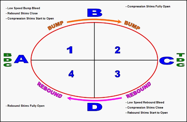
What I meaned to say, if I understand the force vs. displacement graph correctly is that to me the graph starts on the left at the BDC (let´s say -25 mm for the sake of the example) then at the middle it passes the 0 point at which you usally have the highest velocity (and therefore in a "normal/perfect" damper the highest force value)
then it continues to the TDC on the far right side (+25 mm).
Therefore we have an (assumed) total displacement of 50 mm going from -25 mm on the far left to +25mm on the far right side of the graph(circle).
As we see higher forces for bump damping with an increase in compression (area from 0mm to +25mm we have a displacement component which seems to give highest value at ~ +8mm of compression.

Your thought of an flexing connection hose/line, or flexing damper body is (as usual) very creditable.
Another possible explainantion is a too low gaspessure, meaning that due to the nonlinearity of an gasspring we see displacement of the seperation piston unless we have a sufficient force to resist the damping forces.

Image

Image
Last edited by 747heavy on 28 Sep 2010, 16:57, edited 1 time in total.
"Make the suspension adjustable and they will adjust it wrong ......
look what they can do to a carburetor in just a few moments of stupidity with a screwdriver."
- Colin Chapman

“Simplicity is the ultimate sophistication.” - Leonardo da Vinci

User avatar
747heavy
24
Joined: 06 Jul 2010, 21:45

Re: To learn and share about dampers / shock absorbers

Post

this graph shows a damper with an similar caracteristic, and it´s rotated to show BDC and TDC in a more "natural" position.(allowed it´s upside-down, and shows the effect more pronouced on the rebound side)

max. velocity (and therefore normaly max. damping force) is at the 0mm line.

Another possibility for such an "offset" could be flexure in the damper dyno itself, possibly by using a Z or S type loadcell instead of an "pancake" type one.

Image
"Make the suspension adjustable and they will adjust it wrong ......
look what they can do to a carburetor in just a few moments of stupidity with a screwdriver."
- Colin Chapman

“Simplicity is the ultimate sophistication.” - Leonardo da Vinci

Belatti
Belatti
33
Joined: 10 Jul 2007, 21:48
Location: Argentina

Re: To learn and share about dampers / shock absorbers

Post

Thanks both 747 and Dave!

For an obvious reason (although I doubt somebody from my working environment can read this) I didnt plot graphs from the shocks in our race cars.

When I wrote "standard" I meant the shock as it came from the manufacturer, without our "touch" :wink: . I just made the test to plot it here and discuss the subject. It was setuped at the middle range of the availiable "clicks", it does have remote reservoir with flexible hose, gas pressure was arround 200psi, has a 5/8" shaft, with 4.2" travel (the test was made at 1" displ.).
DaveW wrote:Belatti: Beautiful plots (apart from the meaningless middle one).
I think its meaningless, too. Its just a curve built using only 4 points of graph 1 at max speed. Hence its not even a "peak" force graph but a force at "peak" velocity one. That graph dont show us what happens between the rest of damper travel and also is unable to tell us about characteristics like this "asymetrical" potato graph 1. However it is true (as was mentioned) that is a graph that "the industry" uses to have a fast look of the damper.
"You need great passion, because everything you do with great pleasure, you do well." -Juan Manuel Fangio

"I have no idols. I admire work, dedication and competence." -Ayrton Senna

DaveW
DaveW
239
Joined: 14 Apr 2009, 12:27

Re: To learn and share about dampers / shock absorbers

Post

Damper pressure/velocity characteristics can be very complex when looking down in the fine detail. I like to simplify matters by thinking of a real damper as comprising an "ideal" one with a spring in series with it. For the type of damper Belatti tested, the spring stiffness will be different in compression & rebound, because the internal pressure required to generate a given force is different (higher in compression). Hysteresis is caused mainly by energy stored & released by the series spring (stored in your quadrants 1 & 3, & released in your quadrants 2 & 4).

The model is complicated, for Belatti's damper, by fact that the delta pressures are not always greater than charge pressure, which admits the possibility of cavitation if the charge pressure is not high enough. Hence your thought about charge pressure is a good one. I rejected it because I would have expected the mean pressure to increase with increasing temperature, which would (I thought) reduce the possibility of cavitation. In my experience cavitation is normally observed by a "bite" removed from the "ideal" ellipse in your quadrant 3.

DaveW
DaveW
239
Joined: 14 Apr 2009, 12:27

Re: To learn and share about dampers / shock absorbers

Post

747heavy wrote:Another possibility for such an "offset" could be flexure in the damper dyno itself, possibly by using a Z or S type loadcell instead of an "pancake" type one.
Good observation. Damper (rather than dyno) position must be measured in that case.

Belatti
Belatti
33
Joined: 10 Jul 2007, 21:48
Location: Argentina

Re: To learn and share about dampers / shock absorbers

Post

DaveW wrote: In my experience cavitation is normally observed by a "bite" removed from the "ideal" ellipse in your quadrant 3.

You mean this?

Image
"You need great passion, because everything you do with great pleasure, you do well." -Juan Manuel Fangio

"I have no idols. I admire work, dedication and competence." -Ayrton Senna