Diffuser functions

Here are our CFD links and discussions about aerodynamics, suspension, driver safety and tyres. Please stick to F1 on this forum.
shelly
136
Joined: 05 May 2009, 12:18

Re: Diffuser functions

Post

marekk wrote: Maybe it's just semantics, but i don't think you can describe diffuser like an airfoil in ground effect.
I wrote that floor+diffuser works like a airfol extradox in ground effect, with a strange shape due to rules limits.
You have two suction peaks corresponding to two changes in direction, and pressure recovery along the diffuser.

You do not need the other part of the airfoil to have something which is producing downforce
twitter: @armchair_aero

marekk
2
Joined: 12 Feb 2011, 00:29

Re: Diffuser functions

Post

shelly wrote: You have two suction peaks corresponding to two changes in direction, and pressure recovery along the diffuser.

You do not need the other part of the airfoil to have something which is producing downforce
You do not need change of flow direction to have downforce either.

Image
http://www.grc.nasa.gov/WWW/wind/valid/ ... ice02.html

shelly
136
Joined: 05 May 2009, 12:18

Re: Diffuser functions

Post

@marekk: the link is interesting but it is a dtudy aboiut separation and reattachement. I think we can not see nor deviation nor downforce here.
twitter: @armchair_aero

marekk
2
Joined: 12 Feb 2011, 00:29

Re: Diffuser functions

Post

shelly wrote:@marekk: the link is interesting but it is a dtudy aboiut separation and reattachement. I think we can not see nor deviation nor downforce here.
But we can see big flow speed-up at diffusers intake - this means lower static pressure and downforce if you replace this horizontal wall with tarmac and turn picture upside down.

My point is the direction of flow doesn't really change the angle - axis of flow's speed is shifted to the center of diff, but still parallel to the ground, even for asymmetric diffuser.

I know this study is far from perfect for our discussion (the biggest difference being our diff is exit driven, and this one is intake driven), but it's the best i could find from trustworthy source.

shelly
136
Joined: 05 May 2009, 12:18

Re: Diffuser functions

Post

marekk wrote:
shelly wrote:@marekk: the link is interesting but it is a dtudy aboiut separation and reattachement. I think we can not see nor deviation nor downforce here.
But we can see big flow speed-up at diffusers intake - this means lower static pressure and downforce if you replace this horizontal wall with tarmac and turn picture upside down.

My point is the direction of flow doesn't really change the angle - axis of flow's speed is shifted to the center of diff, but still parallel to the ground, even for asymmetric diffuser.

I know this study is far from perfect for our discussion (the biggest difference being our diff is exit driven, and this one is intake driven), but it's the best i could find from trustworthy source.
we have no informtion about pressure in this cse, so I do not know if high speed gives low pressure in it. I have understood that you think there is no deviation but only shifting, but around the bend if the flow is attached streamline have to turn because the first stramline has to be parallel to the difuser wall (if for the moment we do not take into accoun boudry layer growth)
twitter: @armchair_aero

marekk
2
Joined: 12 Feb 2011, 00:29

Re: Diffuser functions

Post

shelly wrote: we have no informtion about pressure in this cse, so I do not know if high speed gives low pressure in it. I have understood that you think there is no deviation but only shifting, but around the bend if the flow is attached streamline have to turn because the first stramline has to be parallel to the difuser wall (if for the moment we do not take into accoun boudry layer growth)
As gas flow enters diffuser, it starts to expand.
This expansion is independent from flow's momentum and direction.

I have hard time explaining this in my poor english, but i can try:

An ideal diffuser and ideal gas.

Let's imagine we divide the volume of gas at intake into small cubes. Every cube has well defined vector of speed and mass - momentum.
Inside this cube we have bilions of air molecules, going in random direction with a mean speed equal to speed of sound, bounching from each other milions of times per second.
As those cubes enter diffuser they expand in vertical direction and compress in horizontal direction, filling the empty space to diff top wall - but they still have the same volume, density and mass. No change of direction, just getting taller and thiner all the time to diffuser exit.

I know there is lot of pictures on the net with bended flow lines in diffuser (one of them i've placed in my post few day ago, which is a shame)- but they are simply not true IMO.

This lack of flow bending is the main advantage of diffuser versus wing - you don't loose energy to accelerate air molecules in vertical direction.

User avatar
PlatinumZealot
550
Joined: 12 Jun 2008, 03:45

Re: Diffuser functions

Post

Look at these diffusers on the compressor wheel.

Image
🖐️✌️☝️👀👌✍️🐎🏆🙏

shelly
136
Joined: 05 May 2009, 12:18

Re: Diffuser functions

Post

@marekk: I agree on your explainations of cubes expanding, but that expansions implies vertical moving of thir cog thus streamline deflection with an angle.

Here is what I was loking for, pressure distribution along a working diffuser (tough inviscid):

http://www.grc.nasa.gov/WWW/winddocs/user/tutorial.html


We have the suction peak on the kink (plus small compression zone downstream to put the flow back to straight)
twitter: @armchair_aero

marekk
2
Joined: 12 Feb 2011, 00:29

Re: Diffuser functions

Post

shelly wrote:@marekk: I agree on your explainations of cubes expanding, but that expansions implies vertical moving of thir cog thus streamline deflection with an angle.

Here is what I was loking for, pressure distribution along a working diffuser (tough inviscid):

http://www.grc.nasa.gov/WWW/winddocs/user/tutorial.html


We have the suction peak on the kink (plus small compression zone downstream to put the flow back to straight)
Thanks for link.
Seems like i was a little wrong - expansion in vertical direction is not uniform in asymmetric diffuser, and this shifting of flow lines does contribute to flow acceleration just at the kink.
One interesting implication - expansion speed of hot gases is bigger then cold ones - one more reason to blow the exhaust under the floor.

Can we agree there is suction peak at diff kink, but no significant flow angle
change through diffuser ?

Or even flow slightly turned down in moving car's diffuser, because there is much lower pressure increase on the lower boundary due to tarmac moving with the speed of external flow (in reference frame of the car).

marcush.
159
Joined: 09 Mar 2004, 16:55

Re: Diffuser functions

Post

I always thought it would be a bad idea to have a kink but go for a generous say (80mm) radius at the entrance of the difusser...

shelly
136
Joined: 05 May 2009, 12:18

Re: Diffuser functions

Post

[quote="marekk"] Can we agree there is suction peak at diff kink, but no significant flow angle change through diffuser ?
[quote]

I think thet if we assume attached flow, if the diffuser ends with an angle and not horizontal, we have to consider some flow angle change. For 2011 regs it can not be too big anyway.

I have read some of SLC post on a thread similar to this and they are very interesting, being that he clearly knows what he's talking about. Nice to see that in that thread raptor22 did not flame about kink line not existing.

I think that after having established that in floor+ diffusr we have two suction peaks we can go on by having a closer look at
-how vortices enhance downforce by being squeezed nder the floor
-why it is rear ride height at the kink the dominant parameter affecting mass flow rate under the floor

Think that slc posts are something we can elaborate on
twitter: @armchair_aero

marekk
2
Joined: 12 Feb 2011, 00:29

Re: Diffuser functions

Post

shelly wrote: I think that after having established that in floor+ diffusr we have two suction peaks we can go on by having a closer look at
-how vortices enhance downforce by being squeezed nder the floor
-why it is rear ride height at the kink the dominant parameter affecting mass flow rate under the floor

Think that slc posts are something we can elaborate on
Every goose (except for the foremost one) flying in V formation knows something about lift gains from using vortices to support their wings, so we should be able to find something about it to :)

regarding rear ride hight:

As you change kink ride height, intake area changes much quicker (by percentage) then exit area and so will expansion ratio of the diffuser. For example 5cm at kink and 17,25 cm at exit = expansion ratio of 3,45, 3 cm at kink and 14,25cm at exit = expansion ratio 5,75.

Due to mass conservation law mass flow at intake and exit are equal, so flow at kink has to be much quicker then external.

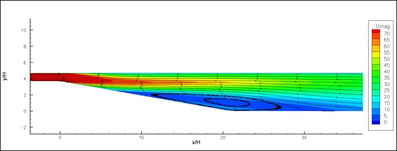
With increase in speed of flow at intake, boundary layer thickness at diffuser walls and reynolds number increases to, eventually causing BL flow transition to turbulent and following separation from the diffuser surface and back flow of air into diffuser.
In this stalled condition only part of diffuser exit area is used to release incoming flow, so expansion ratio drops suddenly, flow speed and downforce at kink decrease abruptly.

Sensitiveness's of this behavior depends (for a given geometry of diffuser) obviously on the initial ride height. Going from 5 to 3cm will result in more expansion ratio change then going form 10 to 7cm.

Inertia of the car and suspension stiffness tend to dump this positive feedback to some extent, but due to low response rate (compared to how quick downforce changes) one can hardly control. it

Up to the introduction of exhaust blown floor/diffuser it was easy to say more diffuser mass flow = more downforce, but not anymore.

You can decrease mass flow by replacing air under the floor with less dense, heated gases of equal static pressure, and if the speed of this heated flow is the same, you still have the same amount of downforce.

In fact, less dense gases have less inertia, so they will accelerate quicker through pressure gradients, so flow speed and downforce at kink increase.

Not to mention higher temp means thinner boundary layer, later transition to turbulent flow and later separation.

shelly
136
Joined: 05 May 2009, 12:18

Re: Diffuser functions

Post

@marekk. let us start from geese. There are two effects related to vortices: upwash/downwash and low pressure in the core of the vortex. Geese use upwash whe they fly in V (low apsect ratio birds!); I think we should focus on the effect of low pressure core when we look t teatray and bargeboard vortices being suked under the floor, where as both downash and low pressure effects are strong when we look at diffuser fences.

Rear height: agree that the lower the height, the higher the expansion ratio.
Shape of diffuser and fences make it work more 3d wise thn 2dwise: what changes when we take this into account?

I do not agree with you on the part about adding exhausts; I think hotter gas will produce less downfoce at the same speed becuse of lower density.
twitter: @armchair_aero

Just_a_fan
591
Joined: 31 Jan 2010, 20:37

Re: Diffuser functions

Post

marcush. wrote:I always thought it would be a bad idea to have a kink but go for a generous say (80mm) radius at the entrance of the difusser...
The rules prohibit it though...
If you are more fortunate than others, build a larger table not a taller fence.

marekk
2
Joined: 12 Feb 2011, 00:29

Re: Diffuser functions

Post

shelly wrote: I do not agree with you on the part about adding exhausts; I think hotter gas will produce less downfoce at the same speed becuse of lower density.
As per ideal gas law:

pV = nRT

pV is constant (the same pressure and volume), so (less density x more heat) = (more density x less heat) = the same static pressure (like in hot air balloons - always at ambient pressure and more or less constant volume, no matter how dense/hot the air inside).

Floor/diffuser downforce is just pressure difference from Bernoulli effect, no significant flow circulation.

It's true that less density = less lift for an airfoil, but this is because both working surfaces of the wing "see" less dense air, and dynamic pressure (responsible for air acceleration around top surface and high pressure buildup on the lower surface) changes linearly with density.


It could be very interesting to get some good simulation of temp maps under the floor of R31.


Regarding vortices:

If you have downforce/lift generating airfoil (front wing, tea tray, bargeboard) you have vortices. You can't have one without the other. Generating vortices consumes energy and it will be nice to reuse this energy on the other parts of the car.

Goose is smart enough to fly in upwash part of vortice leaving upfront goose's wing , so F1 aero guys try to get the low pressure vortice under the floor, to achieve nett gain in downforce. It's all about positioning IMO. If positioned right at the outside edge of the floor, those vortices would act like a virtual skirt for some extent.

Post Reply