Open Source Racecar

Post here information about your own engineering projects, including but not limited to building your own car or designing a virtual car through CAD.
ace37
1
Joined: 30 Dec 2013, 04:45

Re: Open Source Racecar

Post

Looks like a fun project Tim! One of these days I'm hoping to start a project like this of my own. I also like CATIA quite well and have spent some time in the CAD chair with that program.

This may not matter much to you at this point, but if you're still looking into the steels for your cage, we use a common reference in aerospace that you can grab for free and take a look at when you're bored. It's the old US military MIL-HDBK-5 (we use a newer, paid version, MMPDS). The military basically collected a large number of validated material coupon tests, statistically qualified the data, and put it in a big book that was made public so people selling the military equipment could use it as a standard reference. The last military version (Rev. J) is about 70MB, and one direct link is: http://www.everyspec.com/MIL-HDBK/MIL-H ... wnload.php? Steels are section 2. It was built for aerospace, so many materials won't be cost-effective for your project. Also, units are ksi for strength, sorry if you need to convert it.

One interesting page to turn to is Tables 2.3.1.0(d) and (e) on page 2-21, which is PDF page 75. I don't think they did anything with mild steels in that reference (and variation would be high anyway), but a quick google search showed about 300 MPa yield strength and 37% elongation to failure, so you'll probably find the two perform in the same ballpark on impact/crash. 4130 gets you about 2-4 times the strength (depending) with about a proportionate reduction in strain to failure relative to that mild steel result, so impact performance won't be a lot different - how well you do the design and welding (or which is easier for the guy to weld correctly) and other such parameters will likely govern which design performs better in a crash, so 4130 may not be worth extra money.

Looking forward to seeing your progress over coming months/years.

User avatar
Tim.Wright
330
Joined: 13 Feb 2009, 06:29

Re: Open Source Racecar

Post

So I have been quite absent here. Reason being I moved house, job and country again. I like to do this once a year.

I have not been completely idle though. On the design side I have been repackaging the driver position to comply with the regs set out in the English IVA manual for forward vision. This required a more upright seating position to ensure the driver's field of vision is not obstructed by the tyres. So I will have to take the hit of a higher CG with that one.

On the research side I have been playing around with ideas for some interconnected suspensions. I have been discussing the general ideas with some people (including a large advocate of soft twist mode suspensions) on fsae.com. So I have done an analysis and comparison of 3 types of suspensions using an excel sheet I developed myself. Here is the post copied and pasted from the fsae forums:

I have been playing about with the longitudinal Z bars today to try and see in more detail what effects they have on the wheel loads under different conditions. Z bars link front/rear pairs of wheels down one side of the car. They are like an anti roll bar but they resist parallel motion of the wheel pair rather than opposing motion as in the case or an ARB. The advantage being you get your required roll stiffness without an increase in warp stiffness.

While I still believe (at the moment) that for production cars a 2x ride springs and ARB is an acceptable compromise between packaging and ride quality - for a prototype or race car you could repackage or accept some complexity/weight penalty if there really is some performance to gain by running another system.

Enter the Z bar...

I have modelled a system with one ride spring per corner and 1 longitudinal Z bar per side linking the front and rear wheels. The Z bar has different lever arm lengths on the front and rear suspension connections to reach the desired roll stiffness distribution.

I have put this into an analysis spreadsheet which I developed in my spare time. It takes a stiffness martix of the suspension as an input and calculates modal stiffness and responses of the body due to lat/long load transfer, warp inputs at the contact patch and single/dual wheel bump events. I started this spreadsheet over a year ago for the purpose of investigating interlinked suspensions.

It models the chassis/suspension system basically like a 7 post rig. I.e. displacement inputs are given at the contact patches and the body is free to respond vertically and in roll and pitch. Additionally roll and pitch moments can be applied to represent lateral and longitudinal accelerations.

I have modelled the Z bar suspension in this spreadsheet and compared them to:
  1. A traditional suspension system with springs/ARBs
  2. A mechanical interlinked system (all four wheel linked)
All suspensions are matched for roll rate, roll distribution and where possible vertical stiffness and pitch stiffness.

So in terms of responses to vertical loads at the CG here is the comparison:

Image

I have seen that with the Z bars I cannot acheive my desired vertical stiffness and spring centre (point where vertical forces give no pitch angle) simultaneously. This is because I set the bar stiffness to match the roll rate and roll stiffness as a first priority. The body mode shape plot on the bottom shows the vertical displacements of the front and rear axles with the CG shown as a circular marker and the spring centre marked with an X marker. The traditional system and the interlinked system have identical responses, and the Z bars have a very different response.

After some algebra on the system equations, it seems that the vertical and roll responses are not independant like is the case in a traditional suspension. Worse still, the resulting vertical mode that I have got is almost twice as stiff as the traditional suspension and biased too far in front of the CG (23% of the wheelbase). This means it will pitch a lot due to vertical accelerations which is bad for ride (on a road car) and bad for aerodynamics (on a race car).

Another disadvantage, particularly for a race car, is changing either the Z bar stiffness OR the springs results in changes to the ride AND roll AND pitch rates together. Nothing is independant so tuning at the track is going to require a calculator. Any desired roll distribution changes will require disassembly of the main ride springs which on a GT car is a significantly annoying thing to do.

Its not all bad for the Z bars though. There advantages lie in the low warp stiffness:
Image

You can see that I have tuned all 3 suspensions to have the same roll stiffness distribution and same total roll stiffness (top half of the page).

On the bottom half we can see the response to a warp input at the contact patch. Here all three suspensions conform to the warp input identically in terms of the suspension travel, but the Z bar system and the interlinked system show significantly lower load transfers on the front and rear axles. Most of the load transfer on the Z bar suspension is due to the ride springs. This is an obvious advantage as the tyres will see less contact patch load variation due to road irregularities.

After a discussion here a few weeks ago, I have also added an analysis on the sensitivity of the elastic load transfer distribution to a warp input. This confirms Erik's calc which show that very small warp inputs have a very large effect on the elastic load transfer distribution:

Image

Here we can see that the elastic load transfer distribution (ELLTD) changes by 4.6% PER MM of warp input at the contact patch. The Z bar suspension reduces this down to 1.0%. The interlinked suspension can basically eliminate it but this is at the cost of more parts and complexity.

A few other points I found which are not shown above:
  1. I calculated energy dissipated by the body due to single wheel vertical inputs and saw no significant advantages of the interlinked system compared to the traditional system. In fact the interlinked suspension has the disadvantage that a vertical input at one wheel affects the loads on all of the wheels whereas on the traditional suspension only the other wheel on the same axle has a load imposed. When you then calculate the energy from the force and displacement required for the body to find its response equilibrium its the same for the traditional and interlinked system.
  2. The Z bar suspension is about half a stiff in pitch as the trditional system. This coupled with the large distance between the CG and the spring centre will likely result in pitch oscillations which will need to be managed. Then there is the problem of managing pitch angles under braking (critical in terms of aerodynamics) and squat under acceleration.
So, after all that, I have to say my opinion remains unchanged regarding interlinked systems on road cars and race cars i.e. I think they are too complicated for serial production road cars and especially the Z bar solution which is reasonably simple but for me has too many critical disadvantages. For racecars, I think there are advantages to managing the warp mode better and in classes with open rules, I think you could have an advantage with an interlinked suspension, but I feel that Z bars are not the way to go.

However, I may have overlooked something so I'm up for a discussion.

Just a short disclamer: The design work on my own car (which includes this analysis) has been done outside of my work, so my findings and designs done there are more or less "open source" and I'm happy to discuss them. However any aspects which cross over with what I'm doing at work obviously I can't be so open about. So far I've done very little at work on ride, so most of this stuff is fair game for the moment but don't take offense if hold back on answering some things.

Enjoy.
Not the engineer at Force India

DaveW
239
Joined: 14 Apr 2009, 12:27

Re: Open Source Racecar

Post

Forgive me, but I think that the idea of maintaining zero warp loads for an off-roader slithering around on mud might be a good idea, but not for a race car negotiating a circuit.

Ideally, I suppose, an F1 driver would like his car to understeer under braking, oversteer on turn in (to establish the turn quickly), moving to neutral at the apex and then to understeer again under acceleration (to get power down). Without going into details of how this might be achieved, I think that religiously maintaining zero warp loads though a corner would not be a brilliant idea.

If that is accepted, then "ELLTD" would be one of the tools available to achieve that characteristic.

User avatar
Tim.Wright
330
Joined: 13 Feb 2009, 06:29

Re: Open Source Racecar

Post

It's been quite a while since the last update for a variety of reasons (one being I've shifted country again) but the project is slowly going on. I'm also slowly setting up a very small "workshop" here.

I've actually done a fair bit of design work but have not posted it so there is a lot to report. So I will break the info up into multiple posts dealing with specific subjects:
Engine/Layout
Aerodynamics
Body/Styling
Suspension
Last edited by Tim.Wright on 06 Apr 2015, 15:11, edited 1 time in total.
Not the engineer at Force India

User avatar
Tim.Wright
330
Joined: 13 Feb 2009, 06:29

Re: Open Source Racecar

Post

ENGINE/LAYOUT

One major milestone has been the aquisition of the engine. As luck would have it the company that I started working for this year happened to have the 3.0L Alfa Romeo motor + gearbox (from a Lancia fittment) sitting unused in a warehouse and was about to throw it out. Big score that one.
Image

So I set about doing a more detailed layout plan which was largely driven by the mass targets. Recall from ealier that I had decided on a mass distribution similar to Porsche and Lotus which is in the range of 39%. The first thing that hit me was how the transverse engine mounting puts pretty much all of the engine mass directly on top of the rear axle. If you then pack all of the other "moveable" components of the car near to the target CG in order to reduce the yaw inertia you end up with a CG location too far back. In my case I ended up with 35%F which is 4% lower than my target.

To recover this 4% I had two options which I thought about for a long time:
  1. Change to a longitudinal motor installation
  2. Rework the layout of all the major components to put more mass on the front axle
After a lot of consideration I decided that a longitudinal engine installation is going to require a significant amount of design/construction work/costs in areas that I'm not particularly knowledgable in (I'm a suspension/VD guy). Not to mention the need to find a transaxle gearbox. So going this direction would be too expensive in terms of design time, build time and build costs. However, it did graphically demonstrate why a longitudinal installation is the common choice in sports and racecars.

In choosing option 2 I needed to move as many parts to the front axle as I could. This means - all electrical systems, battery, spare tyre and radiators. I also forecast a mass reduction of the engine of 20kg to further help my cause. All of this brought me to the target distribution of 39%F - albeit with a significant (but unquantified) penalty in a larger yaw inertia.

So that left me with another consideration - do I persist with my target mass distribution of 39% and accept a yaw inertia penalty? Or do I try to minimise the yaw inertia as much as possible and accept a different mass distribution?

In the end I have decided to go for the target mass distribution and take the yaw inertia hit. There were a few reasons for this:
  1. A more rearwards biased CG will make the car more OS/unstable in the linear range - and indeed anectdotal evidence seems to back this up for cars such as early lotuses, porsches and other self made rear transverse engined cars.
  2. Even though its theoretically possible to rebalance the car using the tyre sizes - I have seen that 38%F is the minimum mass distribution used by any of the main sports car manufacturers. This suggests that there maybe some practical limitations in the tyres in terms of balancing the car with such an extreme mass distribution.
Basically, without an encyclopedia of tyre F&M data, I wasn't prepared to step out into no-mans-land of tyre sizes and mass distribution.

As it is now, I am very rearward with the CG compared to most manufacturers - so I am still slightly worried about linear range instability. Worried enough to take some further action (see the section on aerodynamics).

Here is my weights table s of today. It's only accurate in the X direction. I have not estimated lateral and vertical CG heights for all of the parts yet. Also the inertias are not yet correct.
Image

I have already included a load of predicted weight savings in the engine. Mainly replacing steel pulleys with aluminium ones, reworking the intake in composite instead of cast aluminium and replacing a load of cast iron brackets with lighter designs in steel or aluminium. For now I'n not touching the internals cause that stuff is expensive.
Image

The suspension is going to be heavier than normal due to an interconnected design that I want to try:
Image

And the rest of the stuff:
Image

The next job to do was to make an engine model. For the moment I'm not using any fancy measurement gear. Just rules, set squares and a camera. I have recently seen a video demonstration of using an Xbox kinetic (I think??) system to create a 3D scan of an object... I will keep that in mind because it might be a worthwhile investment.

Using my agricultural measuring methods I have got something in CAD now which is much more accurate (and bigger!?) than my previous estimation. It was sufficiently different that I have had to completely scrap the rear chassis design and start again from zero.
Image
Not the engineer at Force India

User avatar
Tim.Wright
330
Joined: 13 Feb 2009, 06:29

Re: Open Source Racecar

Post

AERODYNAMICS

Given my slight worry of a rearward mass distribution, I have decided to help rebalance the car using some rear downforce. A very often forgotten effect is the way that vertical load (i.e. from downforce) increases a tyres cornering stiffness. So with some rear downforce, I would increase the rear axle cornering stiffness and therefore rebalance the car towards US/stability.

Its a difficult thing to put a number on at this stage - but I intend to run some calculations to see the sensitivity of the stabilty index or static margin to the rear lift coeffcient.

In the absence of hard numbers (for the time being) I can only present my instincts. Given that I am trying to artificially increase the rear axle cornering stiffness I would like to have the aero balance pretty much 100% on the rear axle - at least at low speed. This means I would need some downforce creating elements at or behind the rear axle and then something at the front to cancel the lift.

In terms of the packaging of a diffuser, the transversal engine installation makes this really difficult. A rear diffuser will have to start behind the engine and extend behind the car. Ideally I'd like to avoid a rear wing because they are a pretty inefficient way to produce downforce and I am not bound by restrictive regulations regarding the diffuser so I'd rather chase the downforce there.
Image

At the front I would like to put a small diffuser, but space is at a premium there due to all the stuff I had to move to the front in order to recover the mass distribution.

The front aero is a little complicated. I have an intake for the radiators too and this, as well as the diffuser need to exhaust somewhere. I have been toying with the idea of sending both the radiator and diffuser air down two channels on either side of the car which would double as side impact absorbtion. It seems visually similar to Nissans LMP1 solution but this is an idea which I've been looking at for quite a few months now. However, the cross sectional area seems too small to use it as a radiator exhaust.
Image

The main packaging problem I have is that channel between the wheel envelope and the body is very narrow so there is not much width available for the front diffuser. For the moment I have put in a diffuser with the following geometry:
Longitudinal length: 620mm
Entry: 300mm wide
Exit: 127mm wide x 166mm high
Angle: 15deg

The radiator and oil cooler are horizontally mounted and will be fed by the big opening in the front which also takes air for the brakes.
Not the engineer at Force India

User avatar
Tim.Wright
330
Joined: 13 Feb 2009, 06:29

Re: Open Source Racecar

Post

BODY/STYLING

This is an interesting area in that its a mix of 2 very different and oten conflicting displines: engineering and styling. Its interesting watching the interaction between these 2 disiplines inside a car company. The interaction is usually done through the "concept" or "layout" department who take inputs from the engineers and the stylists and then make the ultimate decision on who gets to use how much packaging space. Usually a lot of swearing occurs during this process.

After a couple of years observing this interaction I come to a few conclusions:
  1. Us engineers can complain about the constraints imposed by styling as much as we want but at the end of the day it's commercially more important (on a road car) to have good styling than to have an extra 1% of torsional rigidity or cornering grip or whatever else.
  2. Also, at the end of the day, its usually possible to engineer our way around these constraints without too many compromises anyway. Because trust me, I'm an engineer.
  3. Notwithstanding points 1 and 2, I do resent the fact that the engineers have to break their balls to pull weight out of the car because styling/marketing insist on massive wheels and brakes. Then having our balls broken again because our weight saving measures are too expensive.
Obviously the body needs to be functional but after years of design and building I don't want to end up driving something resembling a cock. My aim is to have something clean, with as few intakes/holes in the bodywork as possible in order to reduce the "boy-racer" look.

I had originally toyed with some concepts based on an LMP1 style bodwywork. I.e. a central glasshouse/cockpit with a taperaing nose to the front and largely isolated "pods" covering the wheels. However, given that my car is about the size of a lotus elise, I could not get the proportions to work correctly without it looking like a cartoon or a Caparo T1. Add to that, my 3D surfacing skills are not so well honed, so I tried another angle.

Some playing around with some hand sketches over the cad renderings yielded some better results. I've changed the direction now to be more roadcar and less racecar looking and it seems to help it look a bit less ridiculous. A few styling cues shamelessly robbed from the local supercar manufacturer down the road...
Image
Image
Last edited by Tim.Wright on 07 Apr 2015, 11:29, edited 1 time in total.
Not the engineer at Force India

User avatar
Tim.Wright
330
Joined: 13 Feb 2009, 06:29

Re: Open Source Racecar

Post

SUSPENSION

I've decided to put an interconnected suspension on the car. Its one of the few major complications that I'm adding to the car because I think I can (and have already) learn a lot from its development. And also because racecar.

The main point of any interconnected suspension is to have a better control of the model stiffnesses. The typical targets (or the reasons for adding the complication of an interconnected suspension) are one or more of the following:
  1. Reducing the warp stiffness while maintaining roll and pitch stiffness
  2. Increasing vertical stiffness for downforce while maintaining roll, pitch and warp stiffnesses'
The effects of warp stiffness is something that I am currently researching. Generally warp inputs to the suspension come from the road in the form of road geometry (banking, twist or camber) or road irregularities. In this case, any warp stiffness changes the tyre loads due to these inputs. I have also seen that these warp inputs have a big effect on the load transfer distribution and therefore the balance of the car. I personally consider this a bad thing because these road inputs are largely random - or at least inconsistent corner to corner. If you are able to reduce your warp stiffness, you will have a much better "disturbance rejection" characteristic of your suspension. I.e. it will not change the load transfer distribution due to random road inputs.

At which point I'd like to address Dave's concerns:
DaveW wrote:Forgive me, but I think that the idea of maintaining zero warp loads for an off-roader slithering around on mud might be a good idea, but not for a race car negotiating a circuit...

...I think that religiously maintaining zero warp loads though a corner would not be a brilliant idea.
While I do agree that different vehicle states call for different vehicle balance, I don't believe a passive warp stiffness is the right way to do it. As I have mentioned above (and as I show below in my linear model) any warp stiffness puts your balance at the mercy of random road inputs. An ACTIVE warp control on the other hand - that would be very useful as you have already seen.

Another type of warp input comes from steering geometry. If you have a non-zero kingpin angles and trails (in front and side view), your wheels will want to move up and down with respect to the body when you steer them. However, given that they are effectively fixed to the ground by the weight of the car, instead you see a steering induced load transfer on the front axle which is opposed by an equal and opposite load transfer (assuming equal track widths) on the rear. This is effectively a warp load generated by the warp stiffness of the suspension. And given that its something connected to the steering it could also be something that the driver will feel. In this case the warp load variation is DESIGNED into the suspension as a function of the steering angle. In this case it COULD be desirable and at the least its CONTROLLED (as oppsed to the random road inputs) - Regarding the driver feedback, I have read reports of soft-warp suspensions having bad driver feedback which could possibly be due to this missing ride-steer effect.

To understand the role of the interconnected suspension I have built linear vertical model which simulates practically any type of 4 wheel independent passive suspension by representing it as a 4x4 stiffness matrix. The stiffness matrix is "attached" between the chassis (having pitch, roll and vertical degrees of freedom) and 4 wheel bodies each having 1 vertical degree of freedom. The wheel bodies attach to a mathematical "4 poster rig" via a vertical tyre stiffness. Other effects included are lateral/longitudinal jacking forces, sprung and unsprung weight forces and downforce. In total its a 7 degree of freedom steady state model. Basically a virtual 7 poster rig like this:
Image

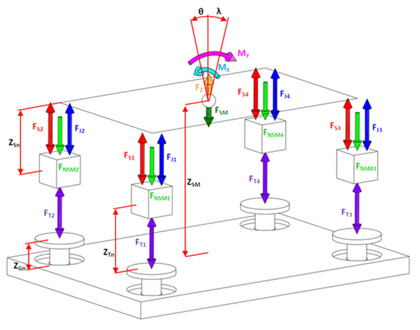
Through building this model I was able to setup a standard set of loadcases and see how the body movements and contact patch loads react. Of particular interest to me was how to reduce the warp stiffness while maintaing the same pitch and roll stiffnesses.

To facilitate this I have developed a couple of interconnected suspension concepts. One which allows independent definition of 3 of the principle suspension modes (vertical, pitch and roll - VPR) and one which allows independent definition of 2 of the principle suspension modes (pitch and roll - PR). Both of these solutions have a nominal zero warp stiffness BUT they have completely controllable roll stiffness distribution.

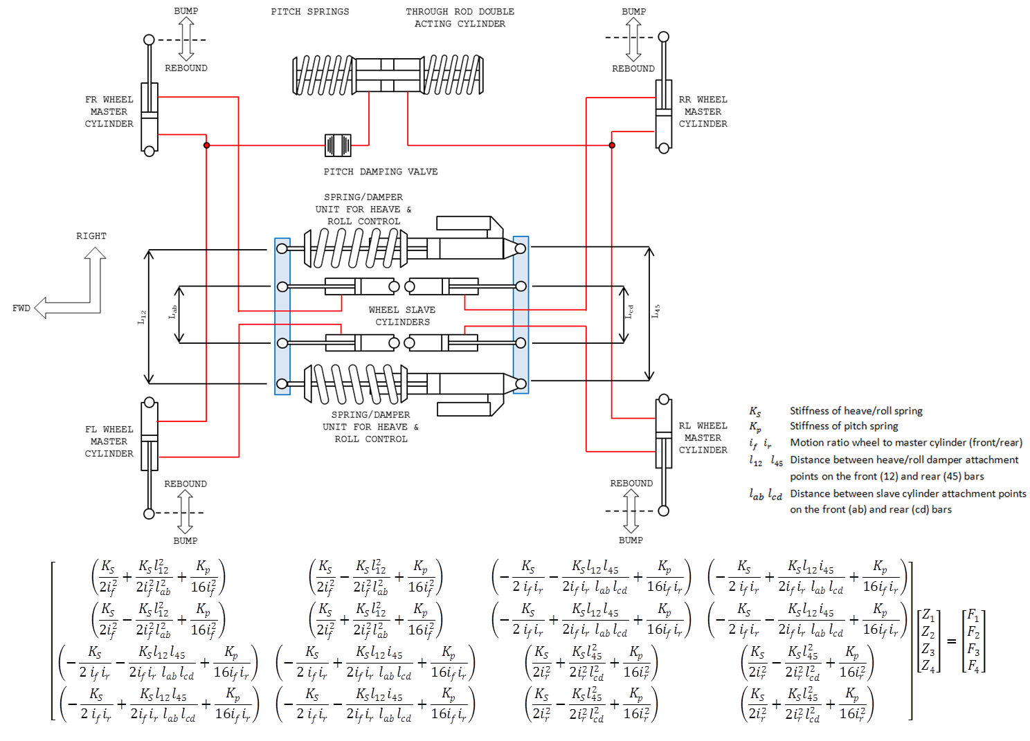
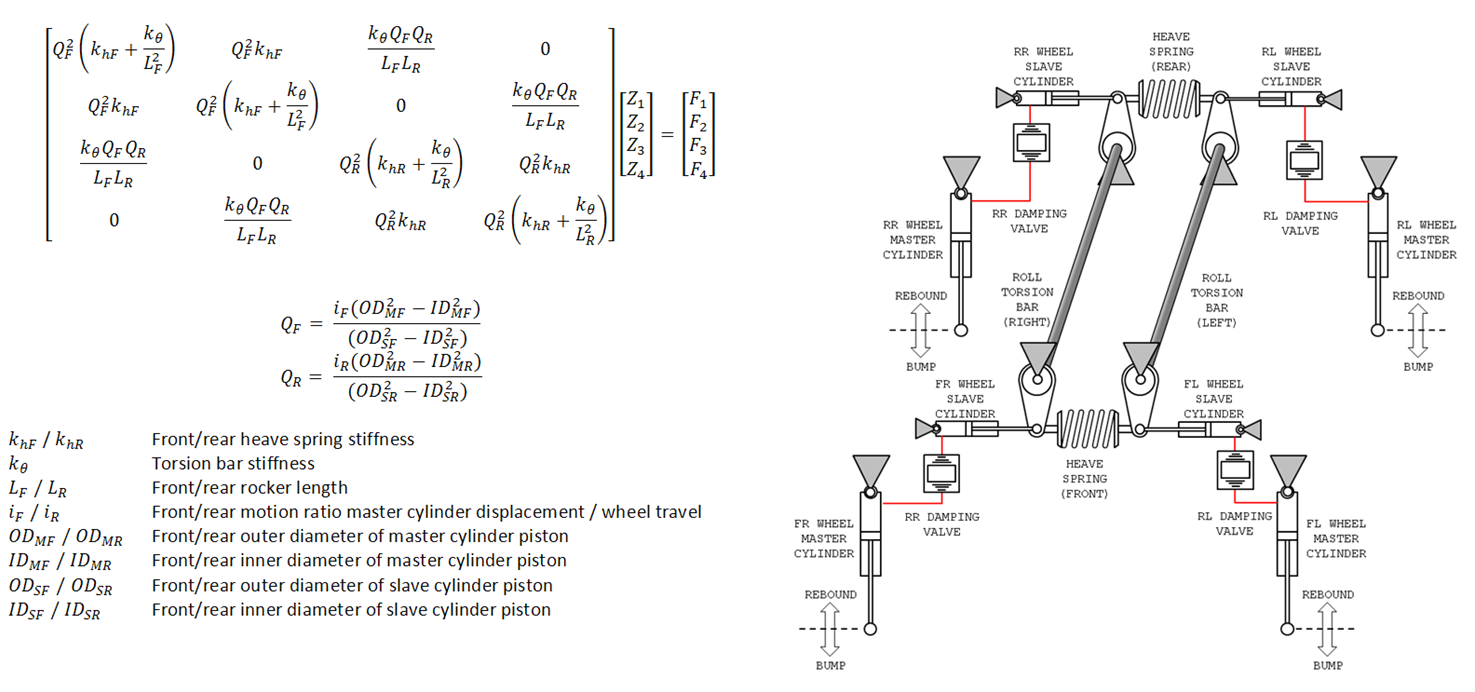
The VPR system translates the vertical wheel movement to a centre module via 4 master-slave cylinder pairs. The centre module is basically 2 cross beams (in blue) which are able to slide (left and right in the diagram) and rotate in the plane of the page in order to follow the 4 wheel movements. Here is the schematic along with the stiffness matrix (note that there are no zero elements - everything is fully connected).
Image
Hi-res

In 4 wheel heave, all 4 slave cylinders contract and pull the two beams together. Therefore the vertical stiffness is set by the stiffness of the 2 heave/roll spring-damper units which work in parallel. In roll the 2 beams rotate in opposing directions, deflecting the heave/roll springs. In this way you can set the roll stiffness and distribution by altering the spacing between the damper attachment points on the front and rear beams. The pitch stiffness is added via another spring which runs from a seperate hydraulic circuit linking the 2 front and 2 rear wheels to act on the pitch spring. In warp the 2 beams rotate like a parallelogram and the pitch spring doesnt work at all, so this is the reason there is no warp stiffness.

All in all, its quite a complicated system. The beams require complicated sliding prismic joints with a rotational pivot to allow roll movements.

The PR interconnected system is a bit more elegant and probably will be the one I decide to use. Like the previous system the wheel movements are transferred to a centre module using 4 master-slave cylinder pairs. Each slave cylinder connectes to a bell crank in the centre module. In the hydraulic circuit I have put in 4 damping valves into the hydraulic circuit to fix the lack of warp damping which is typical of soft warp suspensions. Without warp damping you will not be able to control the wheel mode resonances (in the range of 20Hz) which occur over rough roads. To make these I plan take the piston + valves from a normal damper and put them in a housing which is plugged into the hydraulic circuit. Here is the schematic and the stiffness matrix. Note here the zero elements for diagonally opposite wheels meaning they have no effect on each other.
Image
Hi-Res

The centre module consists of 2 torsion bars and 2 conventional springs connected to the bellcranks. The functionality should be quite obvious from the schematic. In pitch, the front and rear heave springs work like a 3rd spring on an F1 car and the torsion bars do not work at all. In roll it is the contrary - the torsion bars on the left and right twist and the heave springs don't work at all. Pitch stiffness is set by the front and rear heave spring stiffness', the roll stiffness is set by the torion bar stiffness' and the roll distribution is set by adjusting the bellcrank length.

Still reasonably complicated, but with less parts and joints compared to the VPR system.

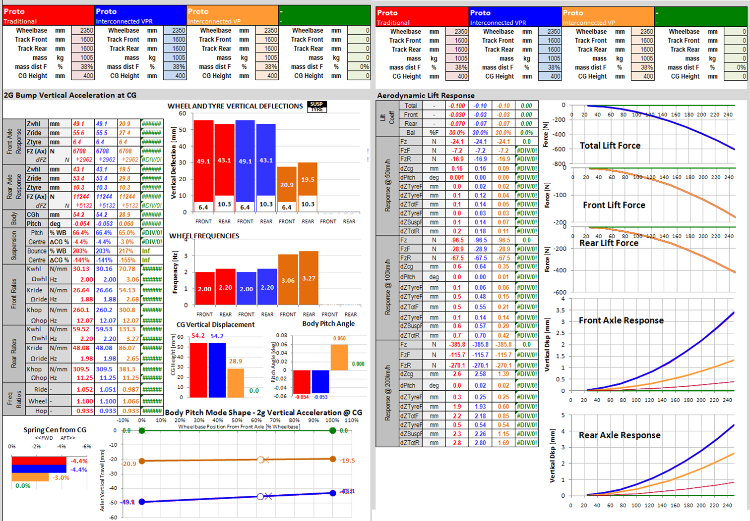
To investigate the two interconnected suspensions I have setup the following 3-way comparison in my model:
Vehicle 1: Traditional suspension (4 springs + ARB's)
Vehicle 2: Interconnected vertical, pitch and roll - VPR
Vehicle 3: Interconnected pitch and roll - PR

All suspensions were setup to give:
Roll gradient of 1.64deg/G
LLTD 43%
Pitch gradient braking: 0.6deg/G
Pitch gradient acceleration: 0.8deg/G

The traditional and VPR interconnected suspensions were also unified in their vertical stiffness'
Front frequency: 2.00Hz
Rear frequency: 2.20Hz

The VP interconnected suspension is not able to independently specify the vertical stiffness. It is instead related to the pitch and the roll stiffness. Actually a traditional suspension has the same constraint. Once you set the vertical wheel rates, your pitch rate cannot be specified independantly. The only suspension here which allows completely independent specification of all of the modes (except warp which is zero) is the VPR interconnected system.

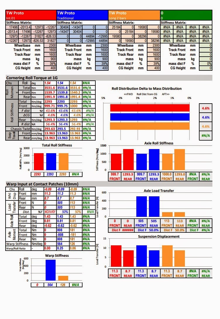
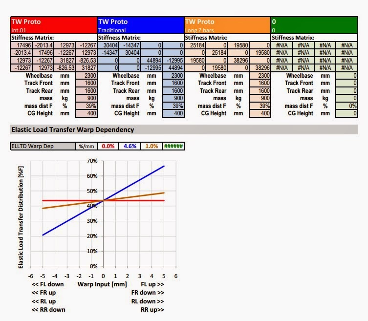
In cornering, all of the suspensions have the same roll gradient and load transfer distribution - but the main difference is the warp load rejection of the interconnected suspesnions. In the bottom diagram you can see the the interconnected suspensions maintain a constant load transfer distribution as the road is distorted in warp by +/-5mm. Instead, the traditional suspension changes its LLTD by +/-17% which is massive. To put that into context, when you make a spring or anti roll bar adjustment on a conventional car, its effect on the LLTD is normally in the range of 0.5% - and a driver will feel this effect. Here, we can see that every mm of road imperfection changes the LLTD by 3.4% for the traditional suspension. So its orders of magnitude larger than what the driver is sensitive to.
Image
Hi-res

Also visible above is the force variation of the wheels in response to a 5mm impact (fixed chassis) and release (free chassis) of the front left wheel. The main point to note is that the load variation of the 2 interconnected suspensions goes to zero as the body responds, whereas the traditional suspension sees a parmanent load change of about 50N on each wheel which is another illustration of the disturbance rejection advantage of the interconnected suspensions. Also apparent is one possible disadvantage of the PR suspensions stiffer vertical mode - during the impact event (before the body responds) there is a much larger total load variation at the tyres.

In pitch there is not much of a difference in performance. I did notice that once you add in an interconnected suspension the classical formulas for determining anti-squat/lift/dive/raise are no longer valid...
Image
Hi-res

The vertical response shows only that the PR interconnected suspension is unable to match the same vertical stiffness of the tradional and the VPR interconnected suspension. The main reason for this is that the 2 springing systems (heave spring and torsion bars) work together in parallel in 4 wheel heave. Whereas in roll and pitch only 1 springing system is working. So in 4 wheel heave, you have the simultaneous sum of the roll and the pitch stiffness' which therefore gives you a vertical stiffness about 2 times that of the traditional suspension.

If this is good or bad is not clear. In terms of load variation a stiffer suspension is a bad thing. However a suspension which is stiff vertically while mantaining a lower roll and pitch stiffness allows you to have enough vertical compliance to minimise load variations but still be stiff enough to resist the high aerodynamic loads (diagrams on the right). In my opinion, the banned FRIC systems would have been doing something like this - which is consistent with the remarks from some of the F1 engineers that they had to increase the ride heights after the FRIC ban.
Image
Hi-res

At the moment I am strongly leaning towards the PR interconnected system because its simpler to make and has less joints to introduce free-play and noise into the system. I may try to deal with the stiffer vertical mode by using non-linear pitch springs which are soft initially (for impact absorption) and then become harder to control pitch and vertical movements. One nice aspect of doing this with the front/rear heave springs is that it does not introduce non linearities into the roll distribution.
Not the engineer at Force India

AlainProst
-13
Joined: 13 Feb 2015, 18:41

Re: Open Source Racecar

Post

Hi Tim !

If you want, I can give you a sketchof a small as the your I did not long time ago and I can adapt this draw for your frame and your dimensions. What do you think ? If you want, I can do many sketchboards for your car because i like drawing and it's not a problem for me so it's a proposal :)

MadMatt
125
Joined: 08 Jan 2011, 16:04
Contact:

Re: Open Source Racecar

Post

Wow just came across this thread now, fantastic job! Haven't read the suspension section yet, but it all makes sens (I have to salute another Catia user :P ). Regarding aero, wings are not inefficient as you say, if designed well, they are very effective and can be placed in regions where their lever effect will help much more to balance your car than a diffuser, but having a diffuser cannot hurt, that is for sure.

I would also consider carefully the slant angle at the rear of your car if you don't want to get lift. I know the length of your car doesn't allow you many possibilities, but that's something to keep in mind.

Going with your weight distribution target is indeed a good choice imo. Inertia isn't bad on its own, it can even be very helpful depending on the track or the conditions. Unless it has the same PMI of a Porsche, I wouldn't worry.

Keep up the good work!

User avatar
Tim.Wright
330
Joined: 13 Feb 2009, 06:29

Re: Open Source Racecar

Post

Hey Matt, thanks for the comments. I've just run a few numbers to give some ballpark numbers for Cl to see if my targets are realistic or not. To get an extra 10% of vertical force on the rear axle (over the staic weight force) at 100km/h I'd need a Cz of -0.635 which is quite high I think. Not sure how achievable this will be since that is already GT2 territory. Not to mention the fact that there will likely need to be some elimination of pos lift before the aero elements create actual downforce.

I think even a 5% increase in vertical force could be useful and for now I'd say that would be the minimum capability I'd specify. That implies a Cz of -0.318, with 100% rear distribution.

Would be interested to hear your thoughts..

Mr Prost, tomorrow I will upload some black and white line renders of the car to use as a template. I'd be interested to see what you come up with.

T
Not the engineer at Force India

AlainProst
-13
Joined: 13 Feb 2015, 18:41

Re: Open Source Racecar

Post

Thanks for your answer !

What are your requirements of the bodywork of your car ? Le Mans Prototypes ? road car as Lotus Elise ? what are the needs of the car in terms of air intake and cooling, what are YOUR personals requirements about the style. All of this in order to have a clearer idea of this yo want :wink:

PS: Scuse me if I don't speak very well English but I'm french and my level in English isn't excellent ! :)

User avatar
Tim.Wright
330
Joined: 13 Feb 2009, 06:29

Re: Open Source Racecar

Post

Here are some black and white line drawings which I use for bodywork ideas:

Image
Hi-res

Image
Hi-res

Image
Hi-res

Image
Hi-res

Image
Hi-res

The style I'm looking for is as clean as uncomplicated as possible. I you look above, my hand sketches are a good explanation of the direction I want to go.

Like I said before, I tried an LMP style but it didn't work because the car is too small, especially in terms of wheelbase. I would like to avoid little aero elements as much as possible. They will be put on only if required. Basically what I'm trying to achieve is a form follows function style. In other words I don't want to put any geometry that doesn't have a function - like fake air intakes/exhausts, massive head/taillights etc...
Not the engineer at Force India

AlainProst
-13
Joined: 13 Feb 2015, 18:41

Re: Open Source Racecar

Post

You said "form follows function" but I have to know what are the needs of your car concerning bodywork, for example, air intakes, exhaust , cooling exits...

In the rendering pictures I saw precedently, I saw a very enormous diffuser. Do you think it's really proportionate for your car ? It will create a big downforce on the rear, while the front of the car hasn't got anything...Personally, I think you don't need an as big diffuser for an as small car but I'm not an expert and I think you know more than me, so I let you do how you think and I hope it will be a success.

I hope to show you a first sketch before one week. I'm not sure but I'll try
Do you prefer a "civilized car" or a race car bodywork ?

Thanks !

rossnzwpi
0
Joined: 24 Dec 2016, 02:33

Re: Open Source Racecar

Post

Hi Tim, I've joined the forum to follow your open source project. Have you continued to develop it?
cheers
Ross (in NZ)

Post Reply