variante wrote:Cannot be done. Rule 3.10.8: Any horizontal section between 600mm and 750mm above the reference plane, taken through bodywork located rearward of a point lying 50mm forward of the rear wheel centre line and less than 75mm from the car centre line, may contain no more than two closed symmetrical sections with a maximum total area of 5000mm2. The thickness of each section may not exceed 25mm when measured perpendicular to the car centre line. Once fully defined, the section at 745mm above the reference plane may be extruded upwards to join the sections defined in Article 3.10.1. A fillet radius no greater than 10mm may be used where these sections joinAnd central RW sections like this I think. Just without the slit.
http://www.formula1.com/wi/full/ta_arti ... le_778.jpg
Basically you would be able to place there only two small lowered sections of the main wing. They may be helpful...but not so much if compared to Renault's solution showed in the image you posted.
This is the only solution:
http://imageshack.com/a/img542/9940/y5qf.png
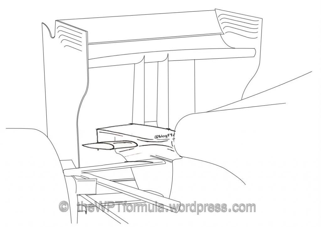
The rule describes the wing supports, not the wing itself.
There can be no dips in the wing section, like those shown, unless most of the wing section doesn't go to the minimum height