Hydristor push-to-pass

All that has to do with the power train, gearbox, clutch, fuels and lubricants, etc. Generally the mechanical side of Formula One.
User avatar
Ciro Pabón
106
Joined: 11 May 2005, 00:31

Hydristor push-to-pass

Post

I was reading in Bussiness Week about the hydristor and, after seeing it can be used as an energy storage device (outclassing the electric motor-battery of modern hybrids) I wonder:

Have any of you ever heard (or thought) of using it with this purpose (energy storage) in mind?

Image

How heavy could it be? After all you could put the thing on the axles directly and use a low-weight bladder for the fluid (2.500 psi). Why is it a bad idea? It's new and it's good so it has to have something wrong we havent't thought about yet... :roll: However, it is one of the cleverest things I've seen in my life.

Probably I shouldn't rant again about how limiting the fuel on board could move F1 carmakers toward really interesting research instead of adding a tenth of a one percent to the aerodynamic shape efficiency... :wink:

You could check the "vision" of the inventor here: for CATIA's fans there is a couple of comments on that software, as a bonus.
Ciro

User avatar
Ted68
6
Joined: 20 Mar 2006, 05:19
Location: Osceola, PA, USA

Post

Very interesting, Ciro, and a bit over my head. But I emailed a link to your post to a friend who owns a hydrostatic motor repair shop and has cobbled together a couple of hydrostatic go-karts for his sons. I'm sure Jim will post a response.

User avatar
Ciro Pabón
106
Joined: 11 May 2005, 00:31

Post

Thanks, Ted68. You're very kind. However ¿what on earth is an hydrostatic kart?

Anyway, the more I understand the concept, the clearer it is to me that this thing really works. Almost all continuosly variable transmissions work based on some sort of belt that goes over two conical shafts.

This thing has a steel belt outside a vane pump. The steel belt rotates with the pump, eliminating practically all friction. It is SUPER ingenious.

For automatics cars it HAS to work better than conventional planetary automatic gearboxes. This thing can influence somehow the efficiency of the "stick-shift impaired" american car fleet.

Besides, the inventor is the kind of crazy dreamer I really like. I'll post later what he thinks about how cars should be built.
Ciro

User avatar
Ted68
6
Joined: 20 Mar 2006, 05:19
Location: Osceola, PA, USA

Post

What's a hydrostatic kart? Bloody Dangerous!!!

Well in this case, it is a small home made tube frame kart powered by a Briggs 8hp motor. The Briggs motor drives a gerotor pump which is fed by a reservoir which in turn feeds a single Vickers type hydrostatic "motor" (as in your Wiki link) at each rear wheel. I have no idea what the horsepower would be of those hydrstatic drives, but it's alot more than the 8hp that the Briggs puts out. The instant torque is amazing.

Guessing that the drives put out 10 hp each, and that the kart weighs 70 pounds.

The drives and pump were scavenged from various pieces of construction equipment that use hydrostatics for raising/extending booms of manlifts and forklifts and such. They're pretty common items. And they make for a wild kart.

DaveKillens
DaveKillens
34
Joined: 20 Jan 2005, 04:02

Post

It's a wonderful bit of equipment, and appears to be the real, practical infinitely variable transmission. The engineering appears to be sound, and the testing is already well past the laboratory and into real vehicles. If efficiencies and reliaibility are as good as expected, this may really be a magic application.

ss_collins
ss_collins
0
Joined: 31 Oct 2006, 15:59

Post

The Hydrostatic racecar concept was explored in Racecar Engineering last year (V15N12 December) a formula SAE car was fully designed but never carried through to manufacture as the money was not available.

Seemed overly cmplex but no reason why it wouldn't work, suspect it could be very heavy though.

User avatar
checkered
0
Joined: 02 Mar 2007, 14:32

Post

Hi Ciro and everyone,

I've been reading through this hydristor material and I have to say I have a feeling there's plenty I haven't quite grasped about the device just yet. The basic realisation in the invention seems to be that in hydrostatics, where the load/force transferring medium (liquid) doesn't compress, the minimum and maximum volumes allowed by the mechanical parts of the device have to be variable in order to regulate the resistance/power ratio. This, in itself is not a novel idea as variable displacement pumps are in widespread use in skid steer loaders and such.

http://www.howstuffworks.com/backhoe-loader8.htm
http://auto.howstuffworks.com/cvt4.htm

So, the innovation must be more subtle and the advantages within the dynamics and engineering of the device. It seems to do away with piston action (save for the volume control) but I have to say the schematics I've found have proven slightly less than clarifying for my contentment, at least.

http://en.wikipedia.org/wiki/Image:Hydristor2.jpg

In this schematic, for example, I just have to assume that the liquid is contained within the steel band and that within every quadrant of the casing there is an inlet/outlet or a valve (apparently not shown, the "kidney"?) that controls the flow. The rotor is turning around, either way, while the pistons (maybe variable compressors would be a better term, as talking about pistons is confusing in hydrostatics when the parts are not in direct contact with the medium) control the relative volumes. But I can't be sure.

http://en.wikipedia.org/wiki/Image:Hydristor1.jpg

In this drawing above (especially the one on the right) there are more aspects that I just can't quite grasp. I am mystified by the "kidney plate", in which the apertures seem to open both in- and outside the steel belt; hardly helpful if one wants to contain the liquid, whichever side of the belt it's on? (if it's on both sides, then I'm truly mystified) The vanes that apparently have a limited radial freedom of motion within the rotor, to separate the compartments of liquid from each other, are not fixed to the malleable steel belt (moving at a slightly different speed as stated, or "walk behind") but the ends of the vanes stay firmly pressed onto it. Is there a spring load on the vanes or how is this achieved?

Where does the hydraulic force that controls the pistons come from? I believe it can't be the equivalent of what the hydristor itself puts out or the controlling function could just be cancelled out. Does the piston action controlling force feature in the overall efficiency figures? And why a four piston array; I can, barely, imagine the hydristor converting mechanical energy (rotation) into hydrostatic pressure, but not the other way around as wouldn't there be points of equilibrium that can't convert any potential energy or change in pressure back into rotation?

That's why, as of yet, I'm also hard pressed to imagine the two adjoining hydristors setup somehow yielding an infinite CVT action. In effect, isn't the single hydristor's variable volume range coupled with any hydraulic "fixed variable volume" engine (as if the hydristor is a "variable variable volume" kind), like the gerotor on line from the hydristor attached to a wheel, a CVT in itself?

http://en.wikipedia.org/wiki/Gerotor

I can, kinda superficially, see the motivation in naming the device a "hydristor" i.e. hydrostatic transistor - as far as I understand anything about the operation of the device in an even remotely correct fashion. Pressure - control pressure, current - control current, yes, there's an analogy there but perhaps not wholly descriptive since as far as I can understand the control pressure need not have anything to do with hydrostatics as such. Couldn't it be mechanically or magnetically induced as well? I'm not going to go into efficiency, yield strengths and such here since grappling with those issues is clearly dependent on accepting and understanding the principle first.

I tend to be overly complicated and thus often end up doing things the hard way, but was just wondering whether anyone had a clearer picture about these sorta things, or perhaps the same questions? Perhaps I'm just being plain stupid with this.

One thing is clear, however. I'm all for devices that radically improve efficiency and are widely applicable. So I couldn't be happier if the hydristor turns out to be all it's pitched for - my intention is not to be sceptical, just openly and positively inquisitive.

User avatar
Ciro Pabón
106
Joined: 11 May 2005, 00:31

Post

Checkered:

The "mode of operation" seems relatively clear to me. I'm not sure if its in "A Connecticut Yankee in King Arthur's Court" that Mark Twain makes his protagonist say "I've never seen a machine whose purpose wasn't clear to me at first sight". I wish I could consult the guy... ;)

We have Manchild in this forum that seems to have this same ability. My son, 8 years old, behaves the same way. I checked with him :) and he understood "the thing" at once with a little coaching from dad. He even did not know what a hydraulic pump was but he got it quite fast: just as smart and handsome as dad! :lol:

I wait for MC to criticize my explanation and I will write to Mr. Tom Kasmer (for the first time in my life) to see if all of the following is "bull manure" or not.

You mention variable displacement pumps. I'm quite familiar with them because I used back hoes "once upon a time" at work. You mentioned also gear pumps (well, you gave the link for "regular" backhoes, where they are mentioned). The concept is similar in a gear pump, like the gerotor, but the implementation is different from variable vane-pumps, the "father" of hydristor. Here you have an animation of one:

http://www.mekanizmalar.com/vanepump.html.

In these vane pumps you could have a spring to "load" or push the vanes against the walls of the container when they are rotating at low speeds, but I think there is no need for them: on one hand, I imagine it must be a "mighty" spring to provide an hydraulic seal, on the other, I also imagine that the starting of the pump would become difficult and would scratch the container walls at low rpm and with low lubrication. Mr. Kasmer would not be able to achive 94% efficiency if he used springs THIS WAY and the belt would not last if the vanes rotated against it.

The seal between the vanes and the container, in a vane-pump is achieved mainly by "centrifugal force" (yes, I know centrifugal force doesn't exist and that I shall speak only of centripetal force, but I know some people won't get it). Anyway, centripetal or centrifugal, this force is enough to provide the sealing if I understand correctly a vane pump.

Now, the genius of the hydristor is to enclose the vanes inside a flexible steel belt: this way the volume of the liquid "inside" the belt is more or less constant (unless it adopts extreme shapes, which it doesn't) but you have, in essence, a vane pump with a variable shape container. Trough the use of "pistons" you can change the shape of the steel belt. Another characteristic (this is another of my wild guesses, again, just by "looking at it") is that the hydristor NEEDS springs to push the vanes against the steel belt: this way you "anchor" the belt at the start of the rotation of the gizmo, and it causes the steel belt to rotate with the vanes! The vanes move "in and out" of the rotor as the belt changes shape. I usually provide enlightening explanations, but in this case I cannot think of a simile. No pump I know behaves like that. This way you achieve a unique pump where you have taken away the frictional losses associated with fixed band designs, like "primitive" conical "gears" and bands.

You don't want to "contain the liquid" inside the steel belt: you need to push it out of the vane pump container, that is, the steel belt. That's the reason why there is a communication between the "inner chamber", were the vanes are, and the "outer chamber", where the fluid under pressure is.

Take a look at the vane pump animation in the link I provided: if you "moved" the chamber to the right (the container is displaced to the left of the vertical simmetry axis, that's why it works), you would reverse the action of the vane pump: it would not pump the liquid upwards but downwards. Do you follow me? I'm assuming the rotor is turning clockwise on both images and that blue is low pressure and red is high.

Image

Now, what the hydristor does is altering the shape of the case or container through the action of pistons. In the following figure you can easily imagine that moving from the "configuration" on the left image to the one on the right side of the image will change the vane pump action from expelling the fluid from the top/down chambers formed by the belt to the left/right chambers, as you state.

Image

Notice that in the other figure you provided (sorry for posting all the figures, I know many people would not follow the links if I did not show them on the post) the "pistons" on the left/right sides are "under" valves (that’s what they seem to me) called "control ports".

Image

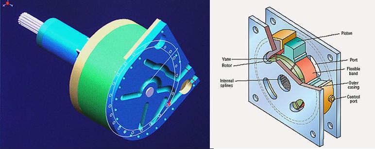
This means that using these ports you alter the shape of the thing. Now, I imagine that the up/down pistons move freely : if you "push inside" the pressure chamber the left/right pistons, the belt changes shape and COULD push those up/down pistons.

As you correctly points out, Mr. Kasmer doesn’t show how the control of these left/right pistons is achieved. Here, my guessing becomes hazier: you could try to find the schema of an hydraulic pump for construction machinery. In these hydraulic circuits you have a “cross valve” that equilibrates the pressure and allows you to vary the amount of fluid that is “returned” to the main tank to keep the “primary” engine under the same workload, no matter how much pressure the operator needs to put through to the pistons that move the machine, no matter if you have the thing at rest or if you are pushing the largest load it can handle. I would use a similar “double” circuit. This is what I imagine could be an alternative to freely floating up/down pistons. Check here:

http://www.automorrow.com/ddbase/automo ... dex_id=415

On that link you’ll find the phrase “Inside the Hydristor you will find two independent circuits which are dual pressure balanced to minimize the torque shaft load”. Mr. Kasmer COULD balance charges, the same way a cross valve (I don’t know the English name) works in a normal hydraulic engine.

Finally, you could also direct the "relative" pressure of the exit ports to different wheels (that's how a tractor turns) or equilibrate the torque on the wheels the way a differential does. The article on the Mag One and the photo it has, without a differential, made me wonder about that. I also thought that, if you pushed the control ports "midway", you could make the belt to become circular, putting the machine in "neutral".

Thanks, Checkered. If you hadn't asked I wouldn't have provided forum members with so many opportunities to: a) criticize my assumptions or b) confirm I'm "losing it". :)
Ciro

User avatar
checkered
0
Joined: 02 Mar 2007, 14:32

Post

Hi,

very good, let’s see if Tom Kasmer can provide something akin’ to “Hydristors for Dummies” for yours truly and any other inquisitively impaired minds at hand. I can easily believe an 8 year old displaying great systems intellect, children often have cognitive abilities far beyond their elders as well they should as much of their potential still remains free of preconception, the inevitable shadow companion of our minds that bask in the daylight of knowledge.

We seem to agree that the innovation in the hydristor consists at least in part of a new mechanical way of varying displacement. I don’t know if I referred to trad. rotary hydraulic pump vanes as being spring loaded (being denser than the liquid they indeed won’t have to be), but wondered if that was the case with the hydristor since the deforming but not yielding steel belt is also under quite hefty centripetal forces, the amounts of which place some strain on the imagination as not so often encountered hydrodynamic and other forces are involved. I have since found (quite enlightening) additional material, here

http://www.designnews.com/article/CA138152.html

that seems to confirm that the hydristor vanes have to be spring loaded. Since they’re under centripetal forces all the same, the potential energy curve of the springs must be peculiar in order to exert the needed additional amount of radial vector aligned pressures – if that additional force is needed under all conditions. That need not be the case.

The flexibility of the stainless steel belt and the inevitable dynamic fluid capacity changes due to controlled deformation was never in doubt or in any way incomprehensible to me. The area of friction is reduced within the area of the control piston heads with the free movement of the belt, and that remaining friction is (at least theoretically) solved by some sort of advanced lubrication, accounting for the better efficiency. By referring to the containment of the liquid my intention was simply to imply that it should be contained within the cycle (containing it just within a hydristor would of course be redundant); I still think that if the kidney plate apertures open both in- and outside of the steel belt (as in the right hand fig. http://en.wikipedia.org/wiki/Image:Hydristor1.jpg ), the liquid will escape to the outer casing which would make little operational sense. It didn’t help my confusion that the liquid cycle apertures, or “kidneys”, are not shown in this image ( http://en.wikipedia.org/wiki/Image:Hydristor2.jpg ). Still, I was under no illusion that the liquid had indeed to “come” and “go” from somewhere.

My greatest misunderstanding of the device was propably due to the same schematic ( http://en.wikipedia.org/wiki/Image:Hydristor2.jpg ) which I took as a representation of two different states of a single hydristor. Perhaps. That, in effect might have been only “half” the story, quite literally. However, in the article you referred to ( http://www.automorrow.com/ddbase/automo ... dex_id=415 ), it is stated that a hydristor contains two steel belts, which makes it plausible that the schematic displays different simultaneous states of those two steel belts/components of the fluidically common but hydraulically separate hydrostatic circuits within a single hydristor. Nowhere was this “detail” specified within the image.

This would make some sense to me. Not foolproof sense, but without going into the actual detailed physical theory of it, some immediate logical sense still. Two adjacent belts providing different variable displacements inducing applicable hyrdostatic forces. I’m not a person who absorbs engineering concepts and designs by written/spoken descriptions in the most efficient fashion possible, rather I tend to conceptualise things in 3D (and I’m quite thankful for the advances in CAD for that). The pictures, as my current understanding of those is, by themselves do not provide sufficient information to describe the concept unambiguously.

Edit: The two belt concept would also allow for the diametrically opposed control pistons to be operated symmetrically. When I imagined just a single belt, I found it doubtful that asymmetrical pressures would bode well for the durability of the steel belt in high RPM.

User avatar
Ciro Pabón
106
Joined: 11 May 2005, 00:31

Post

First, thank you: I don't know if it was "hydristor for dummies" or "hydristor BY dummies"... :D

At first, I did not get your idea. Then I realized that I've been assuming all the time that what you call "kidney plates are not open, as you seem to me you're thinking.

All the explanation I gave was under the assumption that what you called "kidney plates", with the holes or ports through them, have an endplate bolted on them that converts the "holes" into channels. Check the CATIA drawing and imagine you bolt a flat plate on the end of the hydristor: they are not opened to the environment, if you follow my drift.

Look, forget about the plates. Imagine for a moment an hydristor like this one I'm drawing in a hurry:

Image

The blue "tubing" labeled "Input" with a blue arrow is a tube (well, a channel in the plates) that draw hydraulic fluid from a low pressure tank. The vanes compress it (the zone that goes from blue to red, or sort of) squeezing the fluid into a zone that "becomes" smaller because of the form of the steel belt (I'm assuming the vanes are rotating clockwise).

Then there is another "tube", in purple, with a purple arrow (another channel in the plates) labeled "Connection" that communicates the inner area (inside the steel belt) with the external reservoir (in red). From that high pressure area in red, I drawed another "tube" in red, with a red arrow, labeled "Output" that allows the fluid to exit.

The "Connection" is the hole that you think it's a mistake (or that somehow implies you need two belts): it moves the fluid from the inner chamber, surrounded by the steel belt, where the vanes are rotating, toward the outer chamber, outside the belt, where there are no vanes.

When you modify the shape of the belt, the entire contraption reverses its flow, even if it's rotating in the same direction, using a different set of channels. You could also have high pressure fluid in the outer chamber, from a high pressure tank that enters the inner chamber, surrounded by the steel belt, and turn the vanes. Hence Alonso kicks its MacLaren and overtakes Kimi. ;)

My son, after explaining that to him this morning, looked at me very seriously and said the following jewel of a phrase: "You know, dad, sometimes your brain, bright as it may be, is your main enemy. If you want to understand how that thing works, you need to build one". I was awe-struck. The kiddo is right and is half my size (of course, I was not thinking about the hydristor, but my entire life flashed in front of my eyes). :lol:

I think we better wait for the inventor to say something if he wishes. I sent an e-mail to him this morning. Maybe he could think we are "sponge-worthy". :wink: I hope so. This forum connects you with some people in the F1 world and my son Tomas could be right: perhaps Ferrari is more open minded towards innovation: they build their own cars, not like GM that buy the parts, I imagine. Look at how DaveKillens took the idea.

Anyway, thanks for the article you posted: it seems to follow my line of thinking.

If you did not get my previous explanation, don't read this, it could confuse you more (if it's not me who is confused!):

As for the friction between the cylinders and the steel belt I imagine it's relatively low: the pistons only have to extert enough force to change the shape of the belt. The belt is not pressing on them too much, because it has a constant perimeter: it cannot stretch, it's not made of rubber, thus it's not "free" to follow the centrifugal force influence, the way the vanes do. If you take the pump by itself and make it turn, the vanes would be thrown away. On the contrary, if you make the belt to turn by itself, it will not be "thrown away", it simply will adopt a circular shape.

Finally, all the talk about the "cross valve" is how you could connect the different tubes to make the machine "control itself" by redirecting the pressure from one chamber to the control ports, moving the cylinders without resorting to external energy sources.
Ciro

User avatar
checkered
0
Joined: 02 Mar 2007, 14:32

Post

Well, at least one thing was "QED'd" :roll: , I do have a certain amount of self-knowledge:
I tend to be overly complicated and thus often end up doing things the hard way ...
Talking about one's brain being an enemy ... :lol: . I'm certainly wondering about the wiring that has gone into my cortex and the things I've done to it since.

It seems I was imagining, once again, a function that was about ten times more complicated than what is actually the case. Had the compressions (a problematic term since the volume of the liquid doesn't change) been just inside the belt(s?), the corresponding hydrodynamical deformations and required valves would've been ... for the lack of a better word, quite a challenge to an indefinite end. The descriptions of lubrication in reducing friction could've thrown me off as I presupposed an "oiled" machine part operating in air. I'm guessing the hydrostatic liquid has to be repulsive to the lubricant then, which in turn has to adhere to either the outside of the belt or the pistons somewhat.

Simplicity is beautiful and now, at least, I'm content with the theory of it from head to toe. The holes ("kidneys") are in their rightful places as free conduits of the liquid medium towards either direction. Still, I'm bold enough to assume that had there been a complete 3D representation to begin with, I could've avoided all this tedious thinking aloud stuff. :wink: For the lack of a complete schematic (by my own criteria) I can't fault anyone on this forum, however, nor Mr. Kasmer. And I'm interested as to what Mr. Kasmer might be willing to contribute ... I'm also interested in the thermodynamical uses of the device.

If the hydristor is indeed able of significant RPM, the potential for transferring energy is very great - even with a relatively small unit. Thank you for your patience, Ciro.

User avatar
Ciro Pabón
106
Joined: 11 May 2005, 00:31

Post

Yes, I'm also wondering about the lubrication. I guess it must have oil channels (not depicted) that MUST put the oil on the steel belt to lubricate the friction against the pistons.

What I still don't get is why is called an hydristor. I guess I'm missing something and that you are right about the hydrodinamic charges. I've seen it up until now just as a machine to compress the fluid, but your comments made me wonder where is the "transistor gain" if my interpretation is near the mark. I've been pondering a lot about the shape of the entrances and exits of the kidney plate. You can "see" the entrance and exit on the Catia drawing, but then the four chambers are interconnected. Besides, you are right about the article mentioning two belts. If it has "eight chambers", I'm missing something and big.

You're also right about the tediousness of this. I doubt very much anybodyis going to read your wonderful posts or my "word mill" ones. Tomas is right... I should stop thinking and start reading a little more. Finally, I've just taken a long "siesta" and my brain doesn't want to work any more!

As usual, I ask for help to Reca and Manchild, but they seem to have been scared away by our "short prose"... or maybe they're busy as much as I am. :wink: C'mon, guys, help us out.
Ciro

User avatar
checkered
0
Joined: 02 Mar 2007, 14:32

Post

I just hope that

my confusion hasn't confused you. :oops: Also note that quite a few items that I referred to in my earlier posts were (evidently) misconceptions to begin with, so perhaps your earlier notions about the device are still just as valid as they were before I started to ask misplaced questions. I think we can relax about this one, F1 is still two-three years away from adopting a hydraulic powertrain :P . So there's time to wait if Mr. Kasmer is willing to contribute something here.

User avatar
Ciro Pabón
106
Joined: 11 May 2005, 00:31

Post

Well, checkered, my man, you were right on the mark on several things. Mr. Kasmer answered "our" e-mail.

First, you were right about the need (and how critic) is the lubrication and he achieves it the way you made me think, if I got it right. He has achieved an efficiency only dreamt of in hydraulic machinery considering carefully how to lubricate the thing the same way a piston engine does.

Second, he uses two of the gizmos in series to achieve the "gain" and even the modulation of power, sort of automatically, if I get it. This thing is much more than an hydraulic engine: its a clutch, transmission, differential and energy recovery system in one. You can achieve a zero-radius turn with this thing and apparently you can drive power to the wheels without worrying that much about differential slippage.

Third, he doesn't use the double circuit the way I thought: he uses it to balance the loads on the axle, the way a Vickers pump does.

Finally, he is the kindest guy I've encountered in a long time. Considering he is developing the hydristor, he has no reason to explain all that unless he has a heart of gold.

I only hope f1.redbaron or Reca understand how it works and convince their factories to give it a try: I bet people at Ferrari, that build their own cars, are able to appreciate what Mr. Kasmer has achieved, even if they are not american... :wink:

This is the mail:
Tom Kasmer wrote:Hi Ciro, I think you have done a really great job with your writings about the Hydristor. I would be pleased to work with you and explain the magic of the Hydristor. The Hydristor is a machine which converts shaft rotation into variable hydraulic delivery of fluid volume. Think of a hydraulic cylinder pushing a load when hydraulic pressure is applied to the push piston in the cylinder.

Now, imagine a second cylinder plumbed to the first cylinder via a pipe. The second cylinder has a hand lever to push on it's piston. Lets add a sliding tube over the hand lever so that the effective length of the hand lever can be varied, say 10:1 in length. Assume both cylinders have the same diameter of piston.

Case 1: slide the hand lever to max length and push down on the end to cause the second cylinder piston to push in and expel fluid to the second cylinder. The force exerted on the end of the fully extended lever is magnified by 10 times and that 10X force appears at the first cylinder's push output. The hand lever motion is 10X the motion seen at the load.

Case 2: slide the hand lever tube to the 1X minimun extreme. The force applied to the hand lever is directly applied to the piston of cylinder #2 and thence to the output load.

To recap, case 1 sounds like a mechanical lever with a 10:1 advantage and case 2 sounds like directly doing the work. One difference is that I can remotely locate the result of doing the work because I am using hydraulic pipes to transmit the work from point 'A' to point 'B'.

There is another subtle difference here. Using a mechanical lever, I can actually create an infinite ratio. That is done by placing the fulcrum exactly at the point of the load. No matter how much you stroke the lever, no force is required and no load motion ensues.

If you were to move the fulcrum 1/8 inch off the load position, and the lever was 12 inches long, the actual ratio would be 8x12=96:1. A 1 pound force applied to the lever end would create a load force of 96 pounds and a 1 foot stroke (ignore the geometry discussion) would produce a 1/8 inch load motion. If the fulcrum location were 1/16 inch,
the 1 foot and 1 pound of force would equal 192 pounds of load force but the output motion is cut in half to 1/16 of an inch. The point of this discussion is that the hydraulic system described is an imperfect lever and fulcrum as described.

Now, let's consider a mechanical, ratcheting bumper jack and let's add a telescoping handle to this. Each time I stroke the handle to raise the bumper load, the detent clicks in. I can then re-stroke the lever another click to get another bit of bumper height. If I stroke away with a repetitive rhythm, the bumper seems to magically rise above the road. If I were to extend the length of the lever to maximum, the stroking force would be less, but my level of work expended would be the same. It is definitely easier to stroke the longer lever since the force required places a workload on my hand which has it's own force limits. The Hydristor solves this entire dilemma.

In the animation I saw on the website, there is a hydro-mechanical force developed in the direction of the low pressure in both cases. The amount of force is equal to the pressure times the equivalent area of the rotor and vanes viewed along the vertical axis. The original vane pumps were 2 chamber pumps and developed huge side forces on the rotor and vanes and then to the rotor support bearings. The housings had to support these unbalanced forces as well. That design could be easily varied by designs similar in principle to your animation. A 5 Hp variable vane pump in that early design might weigh 300 pounds due to all the metal required to hold it together. Bearing life was short. In 1925, Harry F Vickers invented the dual, pressure balanced' pump which had a modified elliptical chamber (cam ring) to guide the vanes in and out twice per revolution for a total of 4 radial vane motions per revolution. There needs to be a 'kidney port' between the high and low vane motion extremes. The rotational space between any 2 kidney ports must be slightly greater than the rotational space between any two adjacent vanes on the rotor. This prevents oil from bypassing and guarantees that the displacement of oil is directly related to the rotation of the rotor. This design solved the awesome bearing load problem by creating a diametrically opposite and equal force to that of any chamber; hence the name 'dual pressure balanced'. This also created two separate fluidic common but hydraulically separate pumps within the same housing. The rotating vanes have a small but non-trivial mass and the centripetal force of the vanes is speed squared dependent. This is a significant part of the historical inefficiency of the Vickers pump and that number is around 80%. The lifetime according to a Vickers (the corporation) chart is typically 10,000 hours with a 5 micron filter when operating within speed and pressure limits. The pressure is around 2,000-2,500 at speeds up to 5,000 Rpm.

The two thumbnail sketches below your animation show the Hydristor basics of rotor, vanes, and pistons in the two extreemes of piston motion. In the Hydristor, the historical vane tip friction contacting the underside of the belt causes the belt to rotate at near the rotor speed. There is a 'walking mechanism' of contact of each vane acting against the belt where the angularity of force changes 8 times per revolution and each change causes the vane tip friction to 'slip' very slightly. The result is that the belt position relative to the rotor slips slightly behind the rotor speed and the belt life is extended due to the vane friction contact point always moving and no wear spot is generated. The belt also confines the centripetal forces collectively of all vanes. The Hydristor operating speed is very much higher in theory and I imagine designing the flow paths like porting and polishing a racecar intake manifold.

Lets go back to the rotating belt. The belt is always immersed in oil. The contact shape of each piston is not a simple curve. The shape is designed to create a 'rotating wedge' of oil continually trapped between the piston curvature and the belt curvature. This rotating wedge is continually squeezed down to a minute thickness forming a self replenishing
hydrodynamic bearing during rotation. The minimizing effect also creates a self replenishing oil seal which prevents oil under pressure from bypassing the rotation mechanics. The hydrodynamic bearing prevents
direct contact of mechanical friction and this is like a connecting rod bearing in an engine. The first Hydristor was tested at Tecumseh test lab in Ann Arbor, Michigan and achieved 95% overall efficiency. That is
higher that an axial piston pump.

Now, let’s consider how the Hydristor varies oil delivery. If each of the 4 pistons is located equidistant from the rotation center AND is slightly in contact with the rotating belt, there is no net output or input of oil from any of the 4 kidney ports during any range of rotating speed. If the trapped wedge of oil between the rotor diameter, the two adjacent vane surfaces, the belt underside and the 2 contacting flat ends of the housing (the 4 'sealing areas' located between the 4 kidney ports at either end) is, say 1 cubic inch for the sake of discussion, and there are 4 such wedges simultaneously moving through the 4 piston sealing areas, then there is no net exchange of oil through any of the 4 kidney ports.

Now, let’s move the 4 piston positions simultaneously. The 12:00 and 6:00 o'clock pistons move out by .001 inch AND the 3:00 and 9:00 O'clock pistons move in equally by .001 inch. Assume the rotor length is 1 inch for the discussion. Also, assume the pistons/belt contact interface diameter is 2 inches. Looking at the net input of the oil wedge rotating under 12:00, the vanes are extended out .001 compared to -.001 at the 3:00 position for a net of .002 inches. This occurs at a radius of gyration of 1 inch and the axial length is also 1 inch. The area patch created in the direction of rotation is .002 times 1 inch axial length or .002 square inch. For one complete revolution, the 'extrusion of this area patch produces a volume of: (2 pi)(r)(.002) or (6.2832)(.002) = 0.0125664 cubic inch for 1 revolution and for one port from 12:00 to 3:00. The exact same volume of oil is simultaneously extruded from port 3 between 6:00 and 9:00.

Think of a window shade 1 inch wide, .002 thick and unrolling a length of 6.2832, and two of them at the same time. Normally, chambers 1 and 3 will be connected to one output and chambers 2 and 4 will be separately connected to the second output simulating a single pump even though the Hydristor is really a double pump. Obviously, doubling the piston motions will double the volume of the extrusions so that is linear. If you had manipulated the pistons oppositely; that is: moved 12 and 6 IN while moving 3 and 9 OUT, all oil flows would have reversed for the same (assumed clockwise) shaft direction and the linear relationship of outputs versus piston position would have held. If a chamber is outputting oil in a certain amount, the rotationally previous chamber has to supply it.

Theoretically, the output of chamber 1 is equal to the input of chamber 2, to the molecule! Same for chambers 3 and 4. So you have two fluidic separate circuits. Let’s connect the chamber 1 output to the input of a fixed displacement hydraulic right side wheel motor whose return is connected to Hydristor chamber 2. Also, connect chamber 3 Hydristor output to the input of an identical fixed left side wheel motor with it's return connected to Hydristor chamber 4. You now have a hydrostatic transaxle perfect for straight line forward/reverse motion. But how do I go around corners??? Simple with the Hydristor! Let’s go back to the equidistant piston case (called neutral). If I move 12 and 6 out while moving 3 and 9 in, I go forward. If I move the pistons opposite, I back up; all hydrostatically! (Let’s go) back to the circle case. Let’ hold 12 and 6 at the neutral position, and then move 3 to the left and simultaneously move 9 also to the left. Wow, the oil in the right circuit causes the right side axle to go forward. However, the left side circuit oil direction is REVERSED!

This causes the left axle to BACK UP! If you connect the right side
fixed motor to an additional front motor in hydraulic series and separately do the same for the left side, you have the basics for a skid steer machine or an off road 4WD that is really 'trick'. This behavior can be seen in the IFPE video of the John Deere tractor video on the Hydristor website. Now, suppose you simultaneously 'left shift' 3 and 9 and simultaneously 'ellipticise' all 4 pistons to go forward. The tendency to back up the left side is subtracted from the forward motion of diametrically moving the 4 control pistons. The tendency of the right side is added to the forward motion. What happens is that the left side turns specifically slower and the right side turns specifically faster depending on the mechanical placement of the 4 control pistons. It is as if you put a large tire on the right and a smaller tire on the left with a solid axle. With the Hydristor dual differential hydrostatic drive, all differential possibilities are possible.

This is the World's first (and only) differential drive and it gives the same drawbar pull going around turns as a solid axle going straight ahead. In regard to 4WD, if the front tire is smaller than the rear tire, you use a commensurately smaller fixed front motor to turn faster so that the tire tread motion is equal front and rear.

That’s good for a start. Let me know what you think and ask any questions. (Best) regards.

Tom
Ciro

User avatar
checkered
0
Joined: 02 Mar 2007, 14:32

Post

That is absolutely wonderful, Ciro.

I'm sure you'll extend the appreciation of this board, me included, for Mr. Kasmer for taking the time and making the effort. I'm very busy towards the end of the week from here on, so I'll delay devoting an appropriate amount of time and thought to the hydristor to such a moment as when I truly can devote myself to the degree that Mr. Kasmer's thoroughness merits. I only hope my efforts will suffice.