Wind tunnels
Wind tunnels in general are used for testing purposes and aerodynamic optimization. They are specially designed to simulate airflow like in open air and flow velocity as close as possible to reality.
It is of great importance to avoid anomalies, because a slight difference in airflow may change the behaviour of the tested object, and furthermore provide false information to the aerodynamicist, who consequently make the wrong decisions.
Two main types
There are in fact two main types of windtunnels. One type is called open circuit tunnels with an air entry open to the atmosphere. The best way to construct such a tunnel is a blower configuration, where a fan is located at the entry of the tunnel, and blows the air into it. Although the entry swirl is a possible problem, blower tunnels are in general much less sensitive to entry conditions than suckdown tunnels. The exit flow from a centrifugal blower is nonuniform and turbulent, but without the low-frequency unsteadiness of flow entering directly from a room. This type of windtunnel will not be further highlighted, because they are not considered to be the first choice for F1 development.
The most interesting type of tunnels are the closed circuit windtunnels. Also called "racecourse" or "closed-return", which are usually powered by axial fan. Closed-circuit tunnels have more uniform flow, in principle, than open circuit tunnels. These are the usual choice for large tunnels (thus also for Formula One), but care is needed to maintain good flow at the entrance to the contraction. The flow at exit from the fourth corner (counting from the test section) is typically not much better than the exit flow from a centrifugal blower, although the corner vanes themselves have some effect in reducing turbulence (they can be regarded as honeycombs with walls in one direction only).
Windtunnels in F1
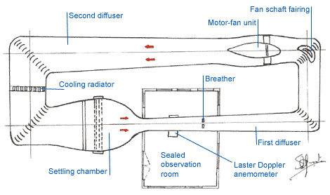
Aerodynamicists speak of F1 windtunnels as a type of low-speed closed circuit tunnels. This means we are talking of airspeeds between 10 and 100 m/s approximately, and tunnels in which the same air is recirculated. The stream is turned, typically by 4 90° corners, each provided with turning vanes placed aside of each other, to prevent turbulence in the corners.
There is always a small vent, called a "breather", somewhere in the circuit so that the internal pressure does not increase as the air heats up during the run. The breather is best located in a part of circuit where inner air is close to atmospheric pressure. Usually that is around the perimeter at the downstream end of the test section. This compensating inflow through the breather is bad for diffuser performance but easy to detect by releasing smoke just outside the breather.

Although some older tunnels have "open jet" test sections (part of the tunnel in the observation chamber), with a floor but no walls or roof (attributed from Gustav Eiffel), this type is not recommended for high performance testing.
Axial Fans
As said before, most closed-circuit tunnels are driven by axial-flow fans, which produce a static pressure rise (with no appreciable change in axial velocity or dynamic pressure). The design of axial fans for tunnels is a very complex matter. It is why F1 windtunnels usually have a specially designed fan to maximize the performance and decrease side effects.
 Because shockwaves might disturb regular airflow at fans with a high tip-speed (axial speed at the tip of a fan blade), fans are developed to keep to tip-speed as low as possible, not more than two or three times the local axial velocity. This causes the blade arrangements to resemble to an axial-flow compressor, with a stator row in front of the rotor. As a return to uniform, non-swirling flow is necessary, the diameter of the central nacelle ("boss", "hub", in which the engine may reside) is kept relatively small, rarely exceeding 50% of the fan diameter. As a result the space between adjacent blades, measured around the circumference, varies considerably from root to tip.
F1 windtunnel fans are usually mounted downstream of the second corner, where the cross-sectional area is two or more times that of the test section. It needs no explanation that a large fan can run at a lower speed to generate the same airflow, thus needing less rpm and reducing vibration, noise and power consumption.
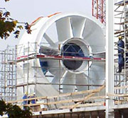
An example of such a fan can bee seen in the picture on the left, which shows the fan of the Sauber wind tunnel at Hinwill. Note that the engine is located in the boss of the fan, which only consists of less than half the fan's diameter.
More information about axial-flow fan design is given by R. Allan Wallis, Axial Flow Fans and Ducts, Krieger Publishing Company (November 1991).
F1 specialties
Because of the very need of high performance, F1 wind tunnels have, apart from the fypical extreme optimizations, special features that increase testing abilities:
- Rolling road: the floor of the windtunnel testing area is made to simulate the track. The idea is to make the track move under the car at the same speed as the air flows around the car. This might seem a worthless feature, but it is in fact far from that. The fact is the simulation is now complete with rotating real tyres. Tyres rotate rapidly at 300km/h, and they are thereby generating a lot of turbulence. The airflow around the wheels is substantially different with rotating wheels compared to a measurement with static floor.
- Ride height simulation: When testing a formula one car, it is fixed to stay in its position with a carbon bar fixed to the car above the air happer. In most current tunnels, these bars have hydraulic systems that allow engineers to adjust ride height with a precision of 0.01 mm, thereby also measuring the resistance provided by the suspension.
| F1 windtunnels examples | |
|---|---|
| Renault
Completion 1999 |
Renault is known to have one of the best wind tunnels at this moment. It was built when the team still drove under the name "Benetton", but was in fact a preparation to the comeback of RenaultF1. The wind tunnel was designed to test a 50% scale model, but can also accommodate a full size formula one car. The rolling road runs at speeds of up to 150 miles per hour. It is also possible to pressurize the tunnel and simulate speeds up to 300 miles per hour. |
| Sauber
Completion 2004 |
The maximum length and width of the steel tube is 62m and 28m respectively, and the largest tube diameter is 9.4 metres. When operating under full load, the power consumption of the system amounts to 3000 kW. This enables wind speeds of 10 to 80 metres per second (i.e. nearly 300 kph) to be reached in the test section. In order to expand the testing capabilities beyond 50% and 60% scale models to production road cars, up to and including the size of vans, the test section will be unusually large. With a 15-square-metre cross-section and a particularly long rolling road, the test section of the Sauber facility is larger than that of any existing wind tunnel fit for Formula One level testing. Sauber's decision in favour of a longer than standard layout for the test section was based on a specific consideration. This layout allows two models to be positioned one behind the other, enabling slipstream and air turbulence simulations. |
