- Login or Register
No account yet? Sign up

Honda F1 project leader Yusuke Hasegawa has outlined a number of reasons why Honda has been struggling so badly in the beginning of the 2017 Formula One season. He confirmed that lots of problems were not discovered while running on the dynamo meter.
Can I ask, why U-shaped crank pins?glenntws wrote:Like I said before, I think there is no way that they use forked rods. However, since this rumor goes around again and again, I think I found a solution which (I think atleast) is comparable to the one from Honda.
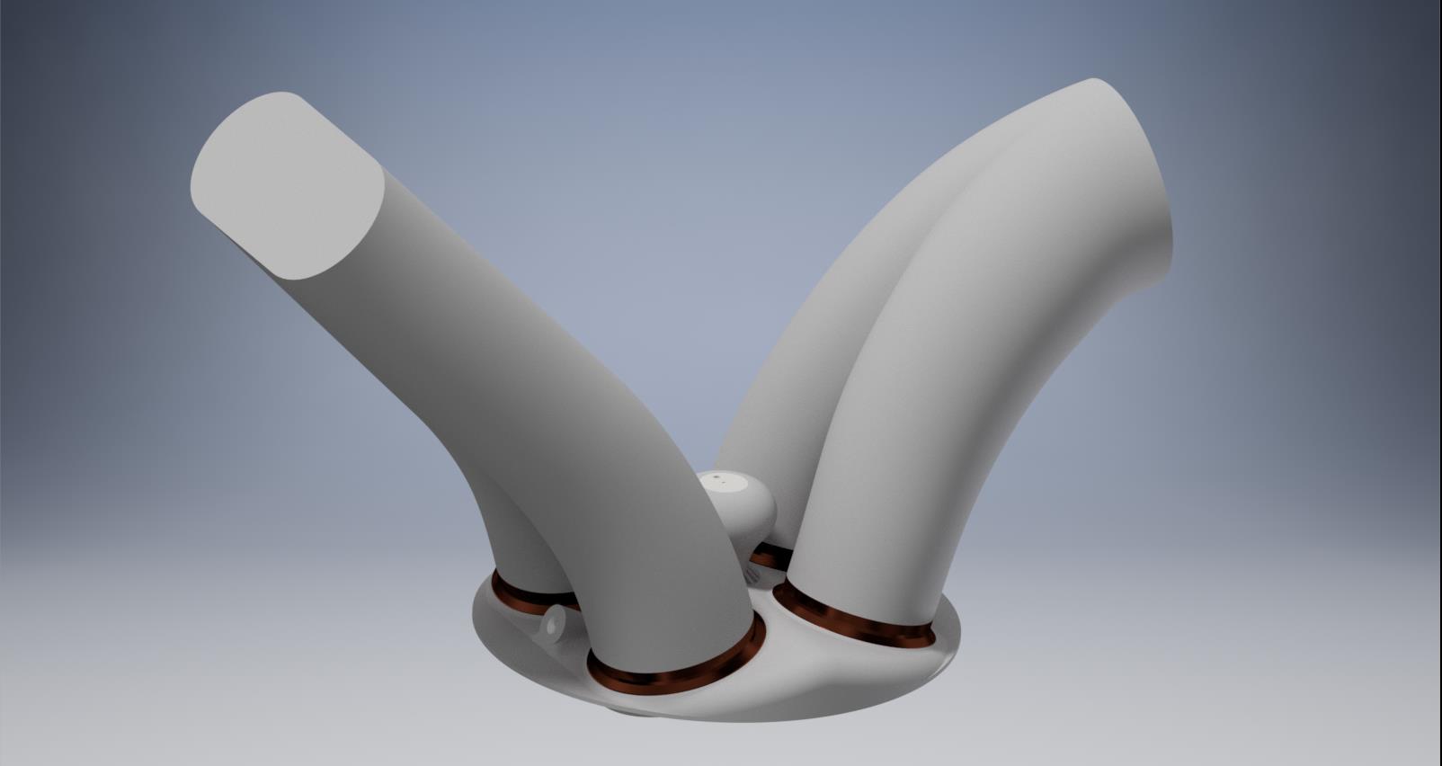
Was about two hours of work in Inventor. Nothing perfect, just made up fast and simple models. Two little simulations give a safety factor of 1.4 at 350bar peak cylinder pressure. I'm sure that, if this model would get perfectionated, they could really have two banks without cylinder offset without using these forked rods no one wants
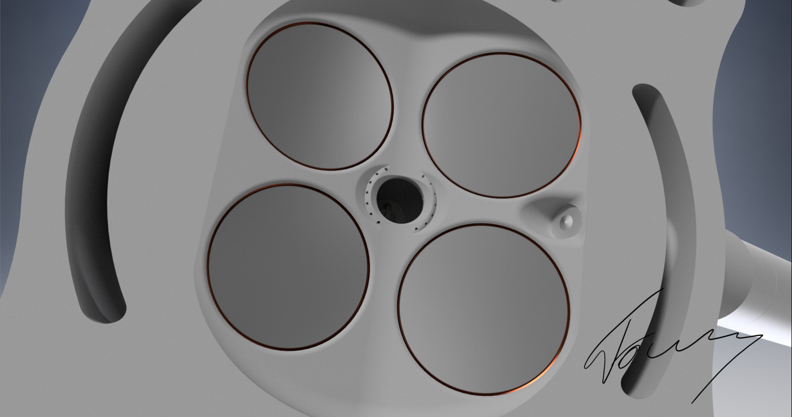
The view from top:
http://fs5.directupload.net/images/170216/3ccxz42y.jpg
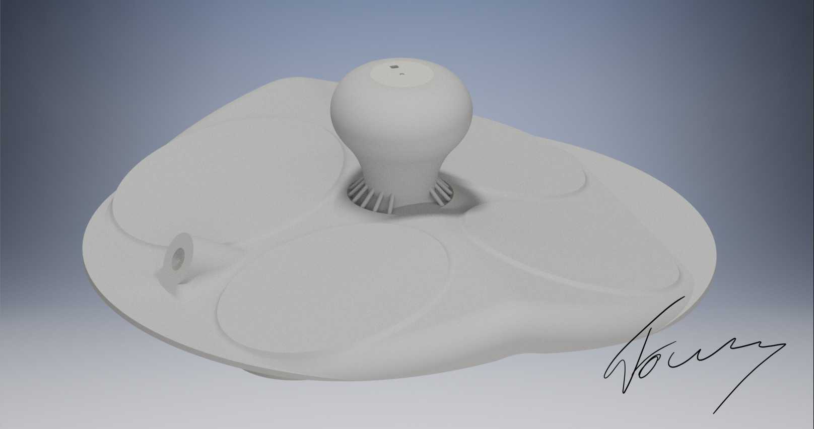
The crankshaft with U-shaped crankpins:
http://fs5.directupload.net/images/170216/54sejwhb.jpg
Also, I'm right now working on a little model of the cylinder head which implements the idea I gave yesterday with the combustion priciple. Maybe I can also realize some little CFD-Simulations, which could give a further hint how things look like in reality.
As in parallel to the axis of the cylinder, rather than parallel to the crankshaft?shady wrote:What if the big end wasnt split longitudinally, but laterally.
The U-shaped crank Pins increase the bearing area which in turn makes the cranktrain safer for higher loads. Also, the oil naturally gets pushed more outwards in higher rpms which Supports the lubrication in the complete bearing area.wuzak wrote:Can I ask, why U-shaped crank pins?glenntws wrote:Like I said before, I think there is no way that they use forked rods. However, since this rumor goes around again and again, I think I found a solution which (I think atleast) is comparable to the one from Honda.
Was about two hours of work in Inventor. Nothing perfect, just made up fast and simple models. Two little simulations give a safety factor of 1.4 at 350bar peak cylinder pressure. I'm sure that, if this model would get perfectionated, they could really have two banks without cylinder offset without using these forked rods no one wants
The view from top:
http://fs5.directupload.net/images/170216/3ccxz42y.jpg
The crankshaft with U-shaped crankpins:
http://fs5.directupload.net/images/170216/54sejwhb.jpg
Also, I'm right now working on a little model of the cylinder head which implements the idea I gave yesterday with the combustion priciple. Maybe I can also realize some little CFD-Simulations, which could give a further hint how things look like in reality.
In your analysis, did you include piston and rod accelerations, which must be significant at 10,000rpm+?
My first thought is that arrangement would induce a side load on the piston to compensate for the moment caused by having the support (the bearing) offset from the load (combustion forces and piston loads).
Would it not be better to make the 'U' the other way? In the rod and cap for example.glenntws wrote:
The U-shaped crank Pins increase the bearing area which in turn makes the cranktrain safer for higher loads. Also, the oil naturally gets pushed more outwards in higher rpms which Supports the lubrication in the complete bearing area.
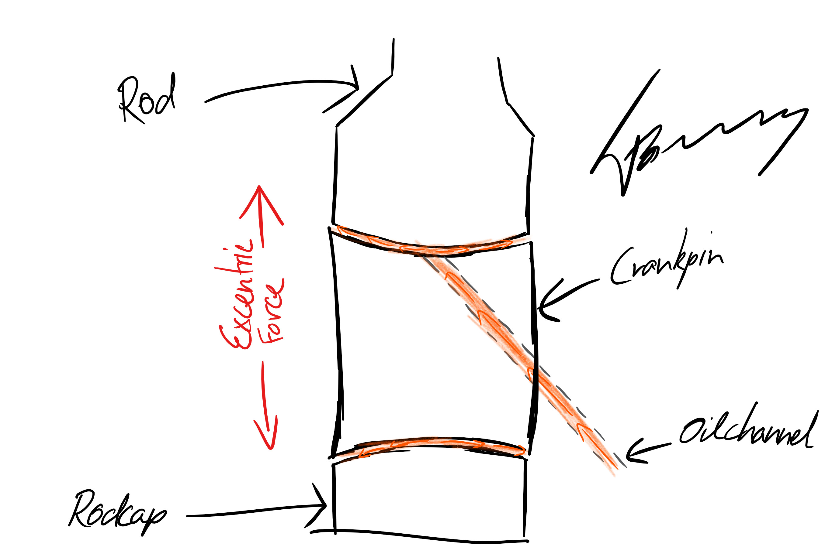
I don't understand you exactly to be true, but i made a little sketch to show you what i was thinking of:ncassi22 wrote:Would it not be better to make the 'U' the other way? In the rod and cap for example.glenntws wrote:
The U-shaped crank Pins increase the bearing area which in turn makes the cranktrain safer for higher loads. Also, the oil naturally gets pushed more outwards in higher rpms which Supports the lubrication in the complete bearing area.
I wonder which one would have more heat loss. The in-piston style chamber or yours. It would be interesting to know.glenntws wrote:
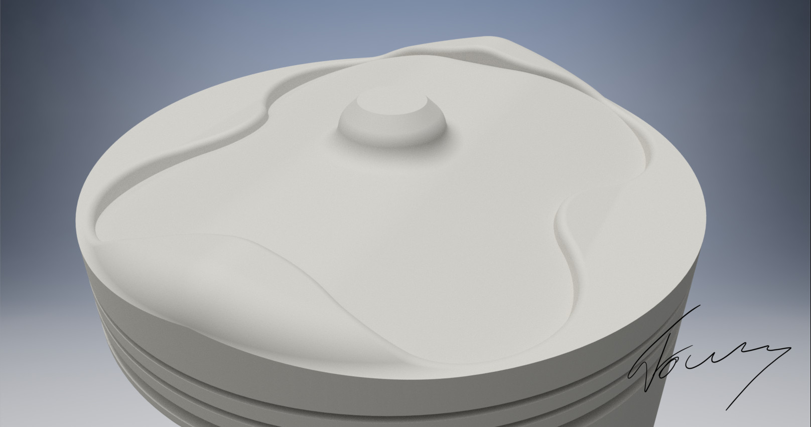
In regards to the combustion idea of yesterday: The 8 hours from right after school to right now have been enough to make a little prototype with the right specifications accordingly to the fia regulations
No bearings?glenntws wrote:I don't understand you exactly to be true, but i made a little sketch to show you what i was thinking of: http://fs5.directupload.net/images/170216/rvw96rw9.jpg
A deeper skirt?glenntws wrote:What I do think, is that the side load on the piston is fairly high at these rpms, so i think that a lower side support would be necessary (like you find it in many street vehicles).
I don't have the idea to inject during intake. The idea is to have a pre-injection almost before the intake stroke is completed to get a lean mix in the whole cylinder. After that, during mid-compression, another big injection is triggered. The injector could have 5 holes. 4 wide angle spray holes and one with a very narrow angle. This center-placed, narrow angled hole would then shoot onto the pin on top of the piston, which also has the role of closing the pre-chamber at TDC. This way, because of the impact and narrow angle, a fast generated, almost stationary, fat cloud will form almost directly over the pin.hurril wrote:Nothing short of awesome work. Truly impressive!
I can see why you would want the injector situated where you've drawn it should its role be similar to that of a port injector (in that it would inject on intake.) But why not mount it where it'd sit next to the spark plug? Not enough room? Beacause it it were there, it would still inject (with a higher pressure) during the intake stroke, and finish off with a short (and fat) pilot injection right before triggering the spark plug.
What do you think?
They are not in the sketch, just imagine them being on the rod. So you can see that the bearings have a convex shape and the crankpin has a concave one. Theoretically you could also apply that to the main bearings of the crankshaft.wuzak wrote:No bearings?glenntws wrote:I don't understand you exactly to be true, but i made a little sketch to show you what i was thinking of: http://fs5.directupload.net/images/170216/rvw96rw9.jpg
You're right with that. Overall, I try to figure out how the engineer's could realize the 0 offset thing, but i'm still sceptical about it. Honestly, in my opinion, I think it's useless to do that and I'm sure they are not doing it.wuzak wrote: A deeper skirt?
The additional side loading adds friction, and the additional support adds some more. So that means less power.