1/4 Scale R/C F1 about the upright

Here are our CFD links and discussions about aerodynamics, suspension, driver safety and tyres. Please stick to F1 on this forum.
firasf1dream
firasf1dream
4
Joined: 18 Apr 2014, 21:26

1/4 Scale R/C F1 about the upright

Post

hello guys,
i hope u all having a good day
well i was searching for more details about uprights because i am trying to design one so i found this topic http://www.f1technical.net/forum/viewto ... f=6&t=8861
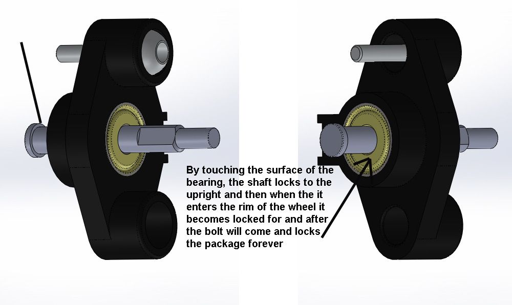
but the problem is that i couldnt understand how does the wheel shaft is assembled in the upright !!?

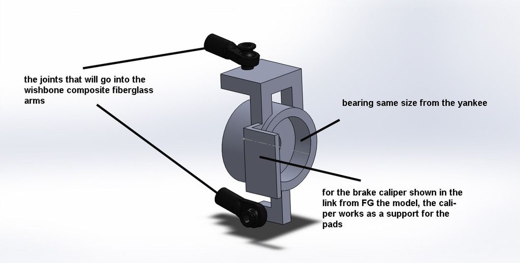
the pictures below shows a model from Yankee cars which i have, modeled it using solidworks so u can see how the shaft is locked to the upright and how the camber can be adjusted and the last picture is another model which i came up with using the same bearing the yankee upright uses, my next calculation would be about using a smaller exterior diameter bearing but for now it would be better to know how does the actual shaft locked in the actual upright ?

for the brakes the model is this one from FG http://rc-car-online.de/shop/en/product ... 1-set.html

Image

Image

Smokes
Smokes
4
Joined: 30 Mar 2010, 17:47

Re: 1/4 Scale R/C F1 about the upright

Post

they are pretty simply on rc cars live axels the use the shoulder of the drive shaft and the nut and the wheel hex drive pin assembly to hold the axel in place.

on the fg cars it may be a little more complex with the disc brake

sgth0mas
sgth0mas
3
Joined: 18 Mar 2015, 03:42

Re: 1/4 Scale R/C F1 about the upright

Post

A good place to checkout different design principles, calculations and processes is in old FSAE papers.

If you google search "FSAE upright design" you will get a lot of information...even the pictures help a lot. See below for an example.

Image

Actually...you can probably use FSAE design papers to assist in a lot of your research.

firasf1dream
firasf1dream
4
Joined: 18 Apr 2014, 21:26

Re: 1/4 Scale R/C F1 about the upright

Post

sgth0mas wrote:A good place to checkout different design principles, calculations and processes is in old FSAE papers.

If you google search "FSAE upright design" you will get a lot of information...even the pictures help a lot. See below for an example.

http://upload.wikimedia.org/wikipedia/c ... sembly.jpg

Actually...you can probably use FSAE design papers to assist in a lot of your research.
thanks for the replies guys
fgthomas it's the reports i use to develope my car :D i printed the reports i have the upright but doesnt help because it doesnt tell how the inside rotate without having a bearing from the inside side like i showed in the RC it's simple and has 2 bearing one from the inside which prevent having full control over where to place the attachment point for the wishbone

User avatar
knabbel
3
Joined: 20 Mar 2012, 16:32

Re: 1/4 Scale R/C F1 about the upright

Post

firasf1dream wrote:
sgth0mas wrote:A good place to checkout different design principles, calculations and processes is in old FSAE papers.

If you google search "FSAE upright design" you will get a lot of information...even the pictures help a lot. See below for an example.

http://upload.wikimedia.org/wikipedia/c ... sembly.jpg

Actually...you can probably use FSAE design papers to assist in a lot of your research.
thanks for the replies guys
fgthomas it's the reports i use to develope my car :D i printed the reports i have the upright but doesnt help because it doesnt tell how the inside rotate without having a bearing from the inside side like i showed in the RC it's simple and has 2 bearing one from the inside which prevent having full control over where to place the attachment point for the wishbone
In a "real car, they normally use 1 bearing, which is pressed in the hub, and then held in place with a circlip. The axle it self is then held in place with a single nut, either on the inside or the outside.

firasf1dream
firasf1dream
4
Joined: 18 Apr 2014, 21:26

Re: 1/4 Scale R/C F1 about the upright

Post

knabbel wrote:In a "real car, they normally use 1 bearing, which is pressed in the hub, and then held in place with a circlip. The axle it self is then held in place with a single nut, either on the inside or the outside.
ah ok so 1 bearing, but what i need to know is how the wheel axe is put in place from the inside ?! as u can see for the 1/4 yankee first picture above, the axle locks on the bearing but how is it done in real f1 ?!

User avatar
knabbel
3
Joined: 20 Mar 2012, 16:32

Re: 1/4 Scale R/C F1 about the upright

Post

firasf1dream wrote:
knabbel wrote:In a "real car, they normally use 1 bearing, which is pressed in the hub, and then held in place with a circlip. The axle it self is then held in place with a single nut, either on the inside or the outside.
ah ok so 1 bearing, but what i need to know is how the wheel axe is put in place from the inside ?! as u can see for the 1/4 yankee first picture above, the axle locks on the bearing but how is it done in real f1 ?!
Here you see that in F1 they use double bearings, and basically the same setup as in your first picture:

https://scarbsf1.wordpress.com/2012/04/ ... t-upright/

Smokes
Smokes
4
Joined: 30 Mar 2010, 17:47

Re: 1/4 Scale R/C F1 about the upright

Post

remember RC cars use radial bearing so they need two to compensate for the thrust in real cars they use an single row roller angular contact bearing to control thrust but also to keep cost down. In race cars you should use a double row roller angular contact bearing to keep the axle geometry in check.

User avatar
flynfrog
Moderator
Joined: 23 Mar 2006, 22:31

Re: 1/4 Scale R/C F1 about the upright

Post

Just a side note your current design is going to be very expensive to build. Milling machines have a pretty tough time doing internal square corners you also have long thin sections that are unsupported that will be chatter prone.

firasf1dream
firasf1dream
4
Joined: 18 Apr 2014, 21:26

Re: 1/4 Scale R/C F1 about the upright

Post

flynfrog wrote:Just a side note your current design is going to be very expensive to build. Milling machines have a pretty tough time doing internal square corners you also have long thin sections that are unsupported that will be chatter prone.
hello flynfrog,
i am now manufacturing my design, the upright will be aluminium allow molding, so what do you think about it ?

N.B: I am now receiving any notification on my email !! what should i do to receive notifications on my email, there must be some checkbox on each post for that, but there is notify me which i think is for notification here on the website ?

Edis
Edis
59
Joined: 31 Jan 2010, 16:58

Re: 1/4 Scale R/C F1 about the upright

Post

Smokes wrote:remember RC cars use radial bearing so they need two to compensate for the thrust in real cars they use an single row roller angular contact bearing to control thrust but also to keep cost down. In race cars you should use a double row roller angular contact bearing to keep the axle geometry in check.
No, in real cars they use double row angular contact bearings. As angular contact bearings only can handle axial loads in one direction you have to use two single row bearings or one double row bearing. The advantage with angular contact bearings is that they can withstand much higher axial loads than regular ball bearings; assuming they are mounted correctly in a "mirrored" pair.

http://www.skf.com/binary/79-61215/457102.pdf

firasf1dream
firasf1dream
4
Joined: 18 Apr 2014, 21:26

Re: 1/4 Scale R/C F1 about the upright

Post

Edis wrote:
Smokes wrote:remember RC cars use radial bearing so they need two to compensate for the thrust in real cars they use an single row roller angular contact bearing to control thrust but also to keep cost down. In race cars you should use a double row roller angular contact bearing to keep the axle geometry in check.
No, in real cars they use double row angular contact bearings. As angular contact bearings only can handle axial loads in one direction you have to use two single row bearings or one double row bearing. The advantage with angular contact bearings is that they can withstand much higher axial loads than regular ball bearings; assuming they are mounted correctly in a "mirrored" pair.

http://www.skf.com/binary/79-61215/457102.pdf
hello Edis,
well about the bearings i read about them in Shigley book, but i couldn't really understand what thrust and radial load actually mean, i made a search on google but still not clear, does radial force represent torque ? does thrust force represent the normal acceleration ?

ChrisDanger
ChrisDanger
26
Joined: 30 Mar 2011, 09:59

Re: 1/4 Scale R/C F1 about the upright

Post

If I may reply here, radial and axial refer to the direction of the force ("thrust") that the bearing might be subjected to (i.e. in the direction of the radius or axis).

These are pictured below, where bearings are generally good at taking radial forces. Bearings allow for very different amounts of axial forces by design - some can withstand very little while others a lot, but sometimes in only one direction.

Image

firasf1dream
firasf1dream
4
Joined: 18 Apr 2014, 21:26

Re: 1/4 Scale R/C F1 about the upright

Post

ChrisDanger wrote:If I may reply here, radial and axial refer to the direction of the force ("thrust") that the bearing might be subjected to (i.e. in the direction of the radius or axis).

These are pictured below, where bearings are generally good at taking radial forces. Bearings allow for very different amounts of axial forces by design - some can withstand very little while others a lot, but sometimes in only one direction.

https://encrypted-tbn3.gstatic.com/imag ... DBhLTGs7kw
hello Chris,
thank you for your reply, yes i know how are the forces on the bearing, but i what i want to understand is what are these forces exactly what does it stand for or come from ?! is Thrust due to weight for example ? is the axial force due to, i don't know traction maybe ? what exactly are these forces ? that's what i couldn't find in other answered questions :/

ChrisDanger
ChrisDanger
26
Joined: 30 Mar 2011, 09:59

Re: 1/4 Scale R/C F1 about the upright

Post

Ah, right. That's hard to explain. It may be best to imagine you're sitting at the corner of the car holding the axle with a bearing in each hand (for a two-bearing hub). So I suppose you are the hub, and for now ignore the suspension and imagine you're fixed to the car. Now, with the car stationary, you have to only support the weight. You will have to apply a moment on the axle by applying radial forces on each bearing. There should be examples in Shigley of this type of arrangement, where the wheel is effectively applying a vertical force at the end of the axle equal to the weight at that corner. If you accelerate, and you're at a rear corner, you will have a radial force pushing the axle forwards, so the force on the bearing will still be radial but more horizontal now. Under braking this force will be radially backwards. Under lateral acceleration (i.e. cornering) you'll see some axial force as your tires push the car sideways and this force is transmitted by pushing the axle along its length, but also the radial forces will change too as the weight effectively changes.

Let me know if that helps.