Honda Power Unit Hardware & Software

All that has to do with the power train, gearbox, clutch, fuels and lubricants, etc. Generally the mechanical side of Formula One.
hurril
hurril
54
Joined: 07 Oct 2014, 13:02

Re: Honda Power Unit

Post

johnny comelately wrote:
22 Mar 2018, 23:44
hurril wrote:
22 Mar 2018, 23:40
johnny comelately wrote:
22 Mar 2018, 23:31
Whoa, back the truck up.

With pre-combustion chambers (of the non-mahle type, where the injector is integral) filling of the mini chamber happens by the main chamber mix getting pushed back up the barrels (by compression) into where the spark is.
The Honda design looks like the diameter for that to happen effectively is way too small (aprox 1+mm) because it is a multi hole design rather than one.
Therefore there needs to be a method to quickly fill the mini chamber and by the drawing in the centre there is what looks like a valve mechanism, but i could be wrong because something like a reed valve could not survive there, but maybe they have developed something novel.
I cannot see anyone ever interpreting that that is an extra valve because it is all internal, where the FIA rules are purely pertaining to the gas exchange. Such arguments are moot.
Care to present some pictures of this Honda mini-chamber?
No I don't.
They are in this thread somewhere.
Are you, perhaps, confusing the creative drawings for what Honda are actually using?

johnny comelately
johnny comelately
110
Joined: 10 Apr 2015, 00:55
Location: Australia

Re: Honda Power Unit

Post

This is the one we use and the dimensions and ratios are important
Image

63l8qrrfy6
63l8qrrfy6
368
Joined: 17 Feb 2016, 21:36

Re: Honda Power Unit

Post

No funny valves.

Image

User avatar
godlameroso
309
Joined: 16 Jan 2010, 21:27
Location: Miami FL

Re: Honda Power Unit

Post

johnny comelately wrote:
22 Mar 2018, 23:31
Whoa, back the truck up.

With pre-combustion chambers (of the non-mahle type, where the injector is integral) filling of the mini chamber happens by the main chamber mix getting pushed back up the barrels (by compression) into where the spark is.
The Honda design looks like the diameter for that to happen effectively is way too small (aprox 1+mm) because it is a multi hole design rather than one.
Therefore there needs to be a method to quickly fill the mini chamber and by the drawing in the centre there is what looks like a valve mechanism, but i could be wrong because something like a reed valve could not survive there, but maybe they have developed something novel.
I cannot see anyone ever interpreting that that is an extra valve because it is all internal, where the FIA rules are purely pertaining to the gas exchange. Such arguments are moot.
5.1.11 An insert within a PU component is a minimal, non-dismountable part whose function is solely to locally support a function of this component. The total volume of inserts within the component cannot be more than 10% of the total volume of the component.
Saishū kōnā

63l8qrrfy6
63l8qrrfy6
368
Joined: 17 Feb 2016, 21:36

Re: Honda Power Unit

Post

I think this reg is mainly for composite tophats/ keenserts etc. Maybe a bit out of context ?

User avatar
henry
324
Joined: 23 Feb 2004, 20:49
Location: England

Re: Honda Power Unit

Post

PhillipM wrote:
22 Mar 2018, 22:34
If you wanted to be really tricky you could conjoin both your valves into a figure 8 shape and actuate it with one stem with a radial constraint, giving you similar curtain area...and leaving you a 'valve' free.
They have to be circular.
Fortune favours the prepared; she has no favourites and takes no sides.
Truth is confirmed by inspection and delay; falsehood by haste and uncertainty : Tacitus

johnny comelately
johnny comelately
110
Joined: 10 Apr 2015, 00:55
Location: Australia

Re: Honda Power Unit

Post

godlameroso wrote:
23 Mar 2018, 00:25
johnny comelately wrote:
22 Mar 2018, 23:31
Whoa, back the truck up.

With pre-combustion chambers (of the non-mahle type, where the injector is integral) filling of the mini chamber happens by the main chamber mix getting pushed back up the barrels (by compression) into where the spark is.
The Honda design looks like the diameter for that to happen effectively is way too small (aprox 1+mm) because it is a multi hole design rather than one.
Therefore there needs to be a method to quickly fill the mini chamber and by the drawing in the centre there is what looks like a valve mechanism, but i could be wrong because something like a reed valve could not survive there, but maybe they have developed something novel.
I cannot see anyone ever interpreting that that is an extra valve because it is all internal, where the FIA rules are purely pertaining to the gas exchange. Such arguments are moot.
5.1.11 An insert within a PU component is a minimal, non-dismountable part whose function is solely to locally support a function of this component. The total volume of inserts within the component cannot be more than 10% of the total volume of the component.
It is an insert in the Honda AND it does not have to be if that is needed as an option. FP2 is on

muramasa
muramasa
58
Joined: 05 Oct 2017, 16:33

Re: Honda Power Unit

Post

Mudflap wrote:
22 Mar 2018, 23:51
No funny valves.

https://i.imgur.com/MUm5lPx.jpg
That translation is like 20-30% wrong or not accurate but should be ok if you are aware of it.

Perhaps need to make sure one thing: do everyone understand that those chamber diagrams are merely guess by the magazine created for explanation/reference? The top one is Mahle TJI recreated based on the research doc made public and the bottom one is "kinda like that" drawing of RA617H's based on what they learned from observation of PU and interview session (obviously they did not reveal anything more than what can be observed from outside ie exhaust side injection).

blueytoo
blueytoo
2
Joined: 02 Mar 2018, 23:37

Re: Honda Power Unit

Post

So with only one injector, must be tricky to get the rich mixture into the prechamber and yet ignite the lean mixture with the combustion jets.

It was poshlated by another poster and commented by Wazari-san. Rich mixture could be maintained near cylinder wall by swirl.

Somehow that can be squished into prechamber , perhaps by a larger peripheral hole that is closed down by rising piston and then ignited.

User avatar
dren
226
Joined: 03 Mar 2010, 14:14

Re: Honda Power Unit

Post

The idea of the rich outer ring negates the use of a prechamber. The statements by Honda engineers show that it's important to get the injector firing direction correct for the prechamber mix along with the main lean combustion mix.
Honda!

User avatar
MrPotatoHead
53
Joined: 20 Apr 2017, 19:03
Location: All over.

Re: Honda Power Unit

Post

Mudflap wrote:
23 Mar 2018, 00:33
I think this reg is mainly for composite tophats/ keenserts etc. Maybe a bit out of context ?
No. It's aimed at things like pre chambers being a part of the spark plug assembly.
This rule was added newly for this season.

User avatar
MrPotatoHead
53
Joined: 20 Apr 2017, 19:03
Location: All over.

Re: Honda Power Unit

Post

muramasa wrote:
23 Mar 2018, 12:40
Mudflap wrote:
22 Mar 2018, 23:51
No funny valves.

https://i.imgur.com/MUm5lPx.jpg
That translation is like 20-30% wrong or not accurate but should be ok if you are aware of it.

Perhaps need to make sure one thing: do everyone understand that those chamber diagrams are merely guess by the magazine created for explanation/reference? The top one is Mahle TJI recreated based on the research doc made public and the bottom one is "kinda like that" drawing of RA617H's based on what they learned from observation of PU and interview session (obviously they did not reveal anything more than what can be observed from outside ie exhaust side injection).
I like this guy ;-)
I've highlighted in bold the important part.
Most of what is reported by the media is the same as this forum - pure speculation.

User avatar
Sieper
73
Joined: 14 Mar 2017, 15:19

Re: Honda Power Unit

Post

Of course, no team will show Any little tidbit of real information, or it must be to deceive, downplay or intimidate. The fact that Honda just openly shares some little bits of information at all is admirable.

User avatar
MrPotatoHead
53
Joined: 20 Apr 2017, 19:03
Location: All over.

Re: Honda Power Unit

Post

Sieper wrote:
23 Mar 2018, 17:25
Of course, no team will show Any little tidbit of real information, or it must be to deceive, downplay or intimidate. The fact that Honda just openly shares some little bits of information at all is admirable.
I think the main fact is that people are taking the images shown in the media to be gospel when they are just interpretations or speculation.
Even in the Japanese Honda articles the text may be from interviews but many of the pictures are just inpretretations from the journalists.

blueytoo
blueytoo
2
Joined: 02 Mar 2018, 23:37

Re: Honda Power Unit

Post

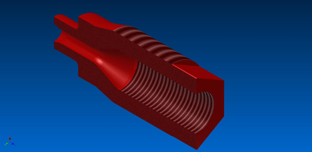
Obviously there is some solution to having one injector somehow fuelling both prechamber and main chamber, whilst maintaining small apertures between the prechamber and main chamber sufficient to direct the ignition jets to the main chamber. This is hard to design, innovative, patentable and hard to copy. Wazari-san maybe provided some clues earlier - he mentioned that the theory on rich peripheral mixture maintained by swirl were clever. Somewhere there are patent applications for things which are compatible with F1's insanely restrictive engine rules.

So far I can find these.

ROTARY-TYPE THROTTLING DEVICE FOR INTERNAL COMBUSTION ENGINE
Aug 28, 2017 - HONDA MOTOR CO., LTD.
A rotary-type throttling device for an internal combustion engine includes an upstream auxiliary intake passageway formed in a throttle body and having an inlet port held in fluid communication with the atmosphere, and a downstream auxiliary intake passageway formed in a cylindrical valve body of a rotary valve and having an outlet port open at a downstream outer circumferential surface of the cylindrical valve body. The upstream auxiliary intake passageway and the downstream auxiliary intake passageway have a body-side joint fluid communication port and a valve-side joint fluid communication port formed in respective sliding surfaces of the throttle body and the cylindrical valve body and designed to overlap each other to keep the upstream and downstream auxiliary intake passageways and in fluid communication with each other. When the rotary valve is open, a main intake air stream passing through an intake passageway in the rotary valve flows smoothly for enhanced intake performance without being disturbed by an auxiliary intake air stream flowing out of the outlet port of an auxiliary intake passage.
https://patents.justia.com/patent/20180080391

CONTROL SYSTEM FOR INTERNAL COMBUSTION ENGINE
Sep 7, 2017 - HONDA MOTOR CO., LTD.
A control system for an internal combustion engine, which is capable of controlling fuel injection valves while causing valve-closing delay time periods, which occur with the valves actually mounted on the engine, to be reflected thereon, thereby making it possible to improve exhaust emission characteristics and fuel economy performance. The ECU of the control system performs initial value-specific control in fuel injection control and ignition timing control, such that initial value acquisition conditions are satisfied, so as to calculate the initial values of the valve-closing delay time periods when the initial value acquisition conditions are satisfied. When normal-time control is performed, the valve-opening time periods of the valves are calculated using the initial values of the valve-opening time periods, and the valves are controlled to be open over the valve-opening time periods.
https://patents.justia.com/patent/20180073460

COMPRESSOR AND SUPERCHARGING SYSTEM OF INTERNAL COMBUSTION ENGINE
Jun 9, 2017 - Honda Motor Co.,Ltd.
A compressor capable of generating a swirling flow at a sufficient speed with respect to a main flow of intake air that flows into a compressor impeller without hindering the main flow. The compressor includes a compressor impeller, a shroud covering a tip end edge of the impeller, an intake duct extending along an axial direction of the impeller, a swirling flow passage being annular around a rotating shaft and having a flow passage cross-sectional area that gradually decreases along the same direction as a rotation direction of the impeller from a base end side where a swirling gas introduction portion is disposed toward a front end side, and a swirling gas ejection passage extending along a radial direction of the impeller. The swirling gas introduction portion is connected to a portion on a downstream side of the front edge portion of the impeller in the intake flow passage.
https://patents.justia.com/patent/20170370378