Dry Sumps in F1

All that has to do with the power train, gearbox, clutch, fuels and lubricants, etc. Generally the mechanical side of Formula One.
mzivtins
9
Joined: 29 Feb 2012, 12:41

Dry Sumps in F1

Post

Hi all!

Dry sumps have popped up a lot in life recently, and i wondered, what challenges do F1 cars have with using dry sumps?
How to they remove air from the oil quickly?
What are the size restrictions (through packaging) of the sump tank?
Is it possible to have a shallow tank (issues with removing air)?
Scavenge points, number of scavenge pump sections vs weight/efficiency?

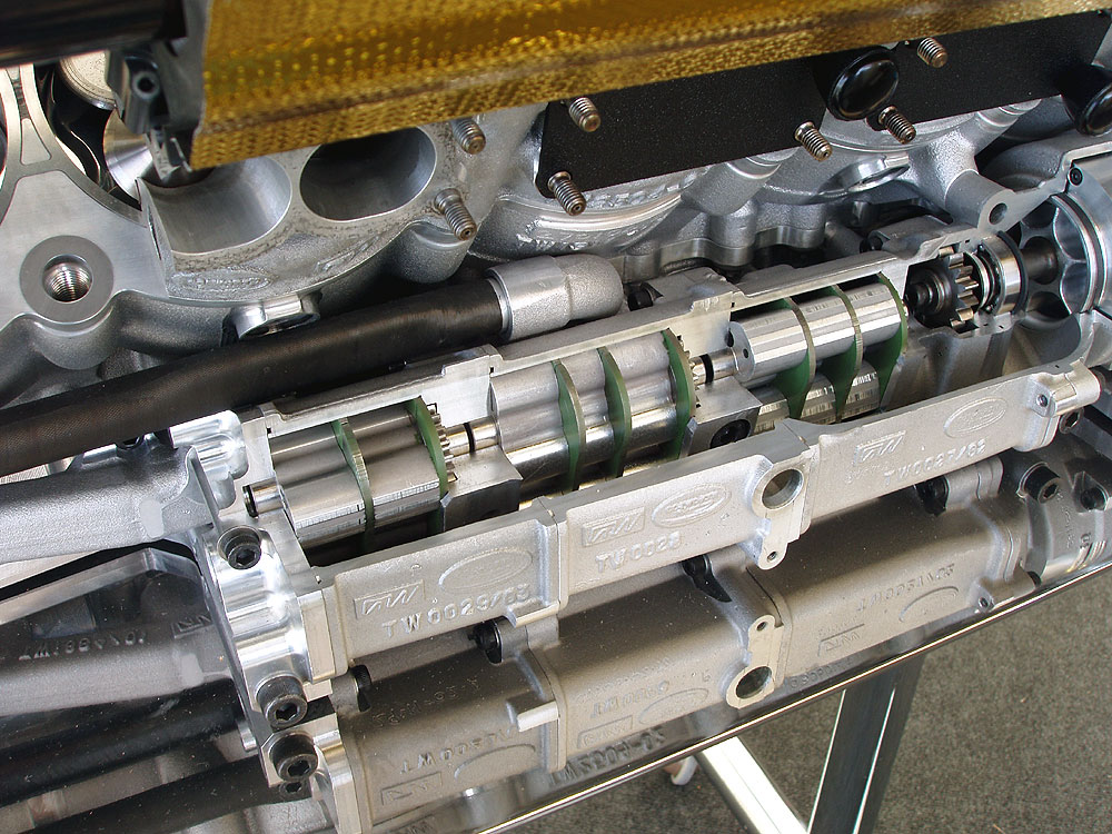
Also any NSFW pictures of pumps more than welcome! :D

saviour stivala
51
Joined: 25 Apr 2018, 12:54

Re: Dry Sumps in F1

Post

Dry-sump – scavenge pumps:-
For an early 1913 dry-sump system detailed information refer too “specification of 50 famous racing engines”.
Official and confirmed dry-sump specification of the FERRARI Tipo 049 90-degree 3.0-litre V10 engine (max power speed 806CV @17500rpm/max RPM 18000. Peak torque 35Kgm @15500RPM. 13.4bar bmep @peak power. 14.2bar bmep @ peak torque. Mean piston speed @18000RPM 24.8m/s. max piston acceleration @ 18000RPM 8890g).
Oil pressure system 1-2bar gear pump running @32.5 percent engine speed.;
11 Eaton scavenge pumps running @35.5 percent engine speed, one Eaton scavenge pump running @32.5 percent engine speed. Oil/air separator running @71.5 percent engine speed.
Oil pump and oil/air separator on the left side of engine and with drive from bottom front of engine.
Scavenge pumps, 2 per crankcase chamber on a common shaft inside a tunnel machined on the outside of the right side of the lower crankcase with cut-outs to each separate chamber, driven from the front bottom of engine.
The oil de-aerator centrifugally separates a large volume of air from the oil drawn from each of the 5-individual V-twin crankcases, the capacity of the scavenge pumps is such that the crankshaft runs in a partial vacuum to reduce windage loses.

mzivtins
9
Joined: 29 Feb 2012, 12:41

Re: Dry Sumps in F1

Post

Wow!that is awesome!

Those numbers are mind blowing, a casual 11 scavenge pumps!

So in f1 and other racing series, they actually use an oil air separator rather than just baffles in a tank.

So in the real world we could lower to height requirements of a tank by having a centrifugal oil/air separator... 75% engine speed! I love f1, even seemingly boring things are just fantastic!

63l8qrrfy6
368
Joined: 17 Feb 2016, 21:36

Re: Dry Sumps in F1

Post

mzivtins wrote:
09 Sep 2019, 11:32
Hi all!

Dry sumps have popped up a lot in life recently, and i wondered, what challenges do F1 cars have with using dry sumps?

From a performance perspective I think that difficulties arise from balancing rotor tip shear losses with tip leakage (regardless of rotor type).

Another important factor is sizing the orifices (orifi?) between the crankshaft bays. While it is widely reported that the bays are isolated, in practice they do communicate through small orifices. It can be shown that for a given engine speed there is only one orifice size that gives the smallest pumping loss. Too large an orifice and the compression work (within the bay, not the cylinder) cannot be recovered as efficiently, too small an orifice and the pumping losses associated with blow-by flow across it increase.

Determining the bore of these orifices usually requires complex 1D gas dynamics models as well as engine tests.


How to they remove air from the oil quickly?

As mentioned by SS, centrifugal separators are used. For nose-fed crankshafts, additional separators within the crank nose were used which use the crank angular velocity to centrifuge some more air out (I think this system was used as far back as the RR Merlin - I'm sure the warbird engine buffs will know more).

What are the size restrictions (through packaging) of the sump tank?
Is it possible to have a shallow tank (issues with removing air)?

First off, the oil tank must fit within the FIA-defined PU boundaries. A tall, narrow tank has two distinct advantages:
It is less sensitive to sloshing and it can provide a higher hydrostatic pressure head at the pump inlet (reducing risk of cavitation) for the same oil mass.


Scavenge points, number of scavenge pump sections vs weight/efficiency?

Quick guess for current engines:
3 (1 per bay) + 2 (1 per head valvetrain) + 1 per timing gears + 1 for turbo = about 7
Gear and roots type pumps have been used in the past. Normally the section capacity is calculated based on the flow rate + blowby in that section. For simplicity all rotors are normally the same outside diameters and the widths are adjusted to achieve the required capacity.

In terms of weight - the rotors tend to be relatively light and are typically made of aluminium alloys since the loads are relatively low. The material is also chosen such that it has a similar thermal expansion as he cover (which is almost invariably aluminium and in maybe 90% of cases 7075 or 2618). For example a steel rotor would lead to excessive tip clearance at operating temperatures.


Also any NSFW pictures of pumps more than welcome! :D

How about this - you can even buy your own! The green coating is xylan. This was used such that the rotor starts off by being in interference with the coating and machines it away when bedding in, ensuring minimal tip clearance.

https://www.racetothefinish.co.uk/mecha ... pump-body/

gruntguru
563
Joined: 21 Feb 2009, 07:43

Re: Dry Sumps in F1

Post

Regarding pumping losses due to communication between bays. These losses will diminish as crankcase pressure is reduced - to zero in fact if a good vacuum could be achieved. Any ideas how low the crankcase pressure is in F1 engines? A google search indicates 20" Hg vacuum (0.3 Bar abs) is not uncommon in other race engines so I wouldn't be surprised if F1 run lower still.

Another benefit of low crankcase pressure, is reduced aeration.

The oil droplet cloud whirling with the crankshaft disappears - oil drops leaving the crank follow a straight path to the nearest wall of the crankcase.
je suis charlie

63l8qrrfy6
368
Joined: 17 Feb 2016, 21:36

Re: Dry Sumps in F1

Post

The boosted endurance engines I'm familiar with are considered healthy if the pressure is below 0.8 barA at peak torque. I don't think they dip below 0.5 barA.

Maybe N/A engines can run lower?

I specifically remember a study on a Triumph 3 cylinder engine being converted to dry sump. The compression mean effective pressure delta between dry and wet sumps was about 0.4 bar which was worth about 5 kW. I can't find what the absolute bay pressures were though.

saviour stivala
51
Joined: 25 Apr 2018, 12:54

Re: Dry Sumps in F1

Post

Since the advent of the NA 3.0-Litre V-10 all manufacturers converged on a design whereupon when the upper and lower crankcases are bolted together a totally separate and sealed from each other and any other engine compartment a chamber for each V-twin cylinder results.
All manufacturers also started using a design that the lower crankcase also incorporated a cast-in scavenge pump/s tunnel with cut-outs to the inside of the lowest part of the lower crankcase on the right side, this as dictated by crankshaft rotation.
Also since that time the roots-type of scavenge pump because of technical reasons lost favor with all bar one of the manufacturers. The majority of manufacturers preferred the ‘torocoid’ pump with rotors having 4-inner teeth and 5-outer teeth, a pump type which is employed as a pressure and scavenge pump. This because of their excellent volumetric efficiency.
The two scavenged pumps per V-twin cylinder chamber set-up, each sealed chamber operates in a partial vacuum.
The scavenge pumps have a trap as well as a relieve valve. The trap is necessary because of the longitudinal and lateral G-forces during acceleration/deceleration and braking.
Formula one scavenge pumps collects a mixture of oil and blow-by gas from inside of crankcase at an absolute pressure of 20-40 KPa, and send the mixture through exhaust channels pressured to levels of between 150 and 250 KPa. This present a compression ratio of between 4 and 12.
Their relief valve on the rotor side reduces scavenge pumps drive resistance by 30 percent. And engine friction by 3 KW.
A magnesium alloy is employed for the inner rotor and a plastic material for the outer rotor. This reduces the weight of the pumps by half.
The vast majority of oil inside each sealed V-twin cylinder chamber (up to a rate of 10 litres/min) comes from the oil-jets injecting oil to the underside of the piston.

gruntguru
563
Joined: 21 Feb 2009, 07:43

Re: Dry Sumps in F1

Post

Very informative - thanks SS.
je suis charlie

saviour stivala
51
Joined: 25 Apr 2018, 12:54

Re: Dry Sumps in F1

Post

gruntguru wrote:
15 Sep 2019, 23:55
Very informative - thanks SS.
Appreciated.

saviour stivala
51
Joined: 25 Apr 2018, 12:54

Re: Dry Sumps in F1

Post

Power supping friction, both mechanical and oil/air friction.
During the NA 3.0-litre V10 era efficiency and weight reduction of moving parts was focused on. Reducing the reciprocating mass because friction and vibration increase quadratically with rise in engine speed. Focus was turned to reduce mechanical loss, and to dealing with vibration acceleration that was reaching 300G.
A factor that effected friction was the valve-train. This power supping friction was reduced from 35KW in the V10 ERA to 12.8KW by 2004.
Power supping friction inside the crankcase. An effort to achieve a compact con-rod locus envelope (surface of con-rod oscillation) the gap between the rotating parts and the inner wall of the crankcase effects oil agitation resistance in the crankcase.
Contrary to many claims development results shows a rapid increase in friction occurring at a gap of less than 3.0mm (from a gap of 3.0mm or less). A test result development graph in front of me shows (1.0mm = 4KW. 1.3mm = 3.2KW. 2.6mm = 0.2kw. 3.0mm = 0KW.)

Smokes
4
Joined: 30 Mar 2010, 17:47

Re: Dry Sumps in F1

Post

saviour stivala wrote:
16 Sep 2019, 17:09
Contrary to many claims development results shows a rapid increase in friction occurring at a gap of less than 3.0mm (from a gap of 3.0mm or less). A test result development graph in front of me shows (1.0mm = 4KW. 1.3mm = 3.2KW. 2.6mm = 0.2kw. 3.0mm = 0KW.)
Isn't this dependant on the type of oil used oil temperature and surface finish of the agitating parts and the speed of the rotor?

Also with the amount of power available would they not be better of with and electrically driven pump?

saviour stivala
51
Joined: 25 Apr 2018, 12:54

Re: Dry Sumps in F1

Post

In my discourse on this here subject I have pushed my technical personal opinion to the side and concentrated solely on facts and figures as happened and were developed since the advent of the NA 3.0-litre V10 era.
“Electrically driven pump”. Many years ago somebody from Australia developed an electrically driven engine cooling water pump for competition use. Yet no formula one manufacturer I know of ever adopted any such electrically driven pump let alone an oil pressure or scavenge pump.
“Type of oil used, oil temperature and surface finish of agitating parts and speed of the ‘rotor!’. I would think that all F1 engine manufacturers would be more or less in the same ball park as regards the ‘use’/ above question/s.

User avatar
humble sabot
27
Joined: 17 Feb 2007, 10:33

Re: Dry Sumps in F1

Post

I just sort of assumed they were electrically driven, figured the losses from driving the pumps would be offloaded.
I learned something new today
the four immutable forces:
static balance
dynamic balance
static imbalance
dynamic imbalance

63l8qrrfy6
368
Joined: 17 Feb 2016, 21:36

Re: Dry Sumps in F1

Post

saviour stivala wrote:
16 Sep 2019, 17:09
Reducing the reciprocating mass because friction and vibration increase quadratically with rise in engine speed.
This statement is one of the engineering mantras that have been bothering me for a very long time.

At first glance it appears perfectly reasonable - the shear force is proportional to the sliding velocity. Since the power loss is shear force times velocity, the power loss is proportional to the velocity squared, however:

1. All tribological contacts within an engine are a combination of asperity contact and hydrodynamic lubrication. Journal bearings can be said to be predominantly hydrodynamic (yet they too exhibit some form of asperity contact, otherwise they would never wear) while piston rings for example operate in in boundary / mixed lubrication regime dominated by Coulomb friction. Since Coulomb friction forces are purely a function of normal force and coefficient of friction, the power loss increases with the first power of velocity. Actually, it has been shown that a "dry" coefficient of friction decreases slightly with velocity.

2. The oil viscosity decreases quite dramatically with shear rate and temperature (see Cross and Vogel models respectively). That means that as the engine speed increases, the viscosity decreases such that power loss does not increase as steeply as velocity squared. Secondly, since most of the that power loss goes into heating the oil it causes a secondary decrease of viscosity due to thermal effects.

This is why it is not at all uncommon to see FMEP traces which are almost perfectly linear with engine speed. In my experience the steepest FMEP increase with engine speed are usually caused by the fluid pumps.

As a side note, in turbomachinery where unbalance forces are significant (the main source of bearing loads) there tends to be a more pronounced friction increase with speed since unbalance forces increase with the square of angular velocity. This is definitely not the case with reciprocating engines where loads are dominating by firing, gears, springs etc. and inertial loads are relatively small.

riff_raff
132
Joined: 24 Dec 2004, 10:18

Re: Dry Sumps in F1

Post

Oil flow rates in the engine are based on cooling requirements. One important factor with regards to dynamic oil fluid film thickness is flash temperature.

The crankcase scavenge pumps typically have volume flow rates >4x the oil discharge volume flow rate. Extracting as much liquid oil and air/oil mist as practical from the crankcase volume is critical for minimizing windage losses. However, it is important to remember that all the scavenged air gets mixed into the oil, and must be separated before the oil is fed back to the pressure pump inlet. Air entrained in the oil flow to the pressure pump can cause cavitation damage.

Image
"Q: How do you make a small fortune in racing?
A: Start with a large one!"