Does the regulations say that the radiators have to be metal?
pitch derived Carbon fiber has a themal conductivity of 800 W/m.K
Aluminum is 250 W/m.K
Carbon makes sense as a radiator, but then it's all limited by the conductivity of air and the water which is doing the heat exchange.
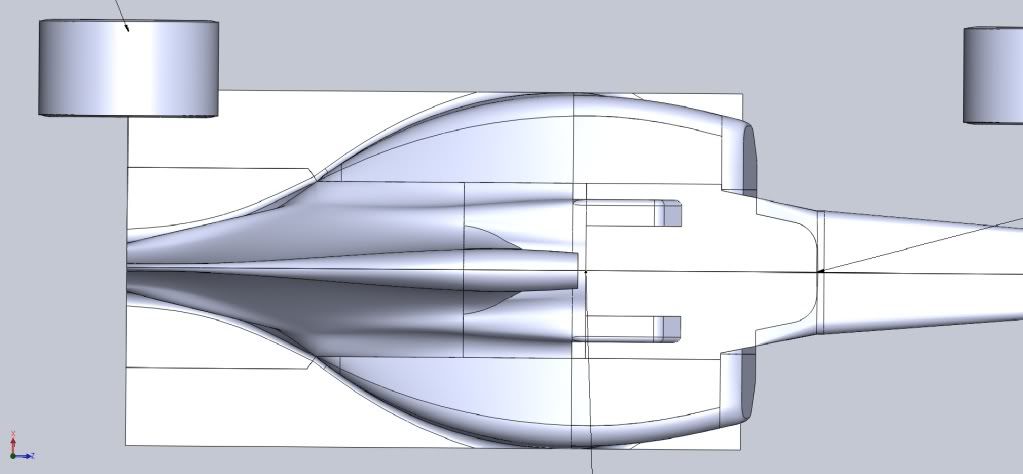
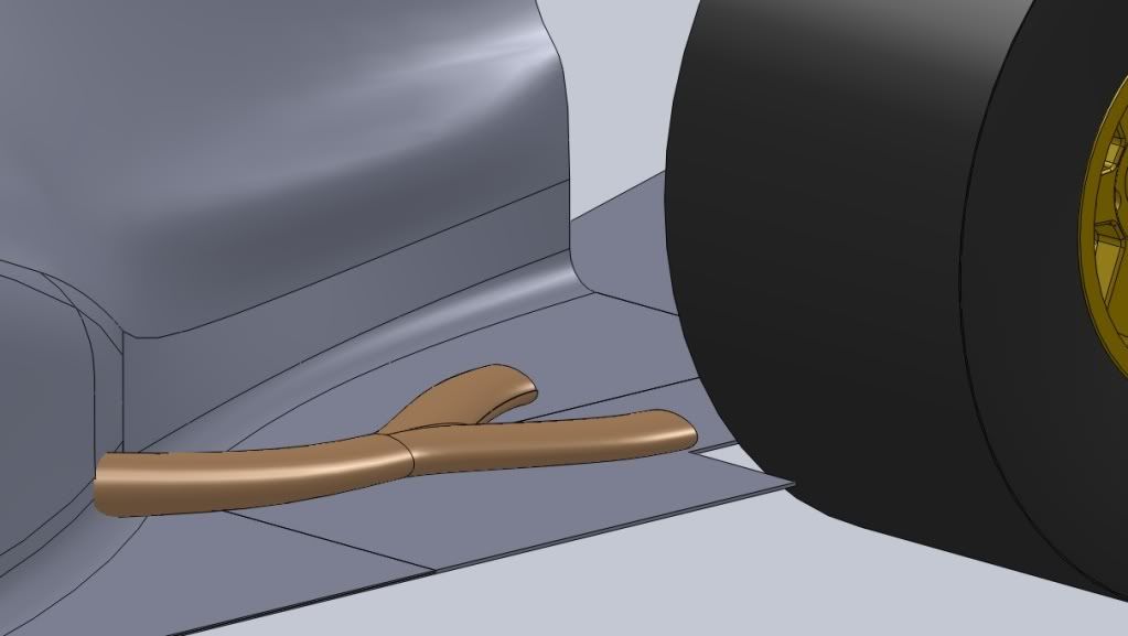
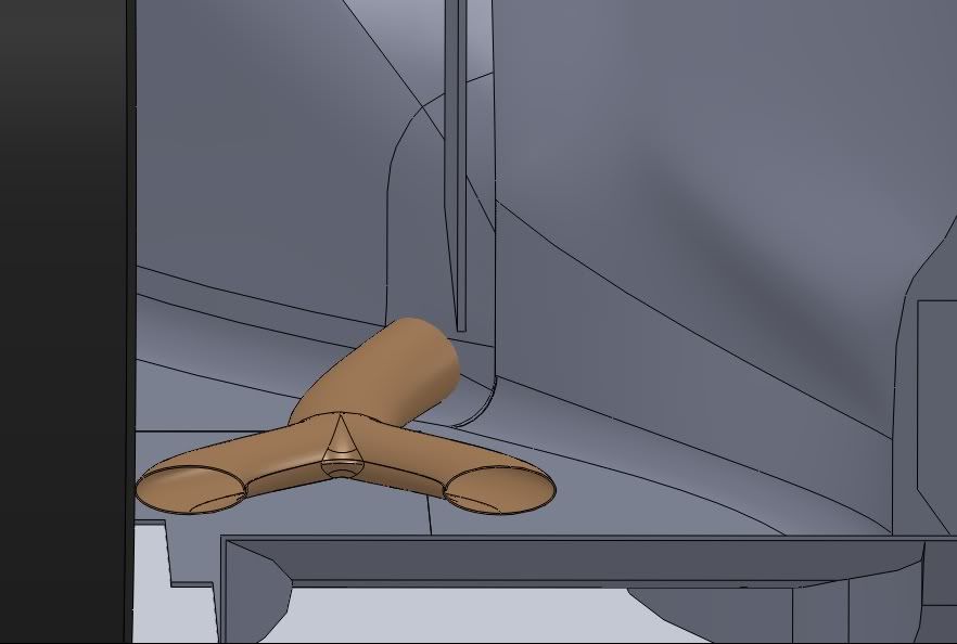
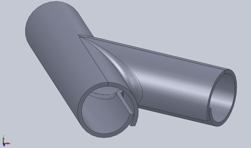
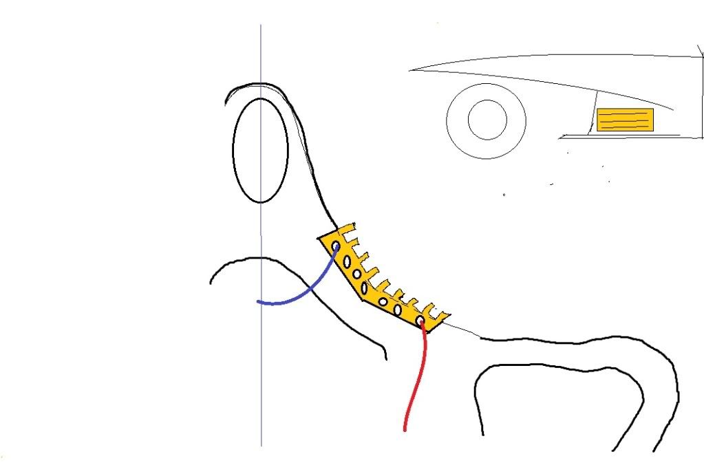
I actually have an idea for a radiator for this design. Maybe i get some time to draft it. The ehxaust isn't finished either, as it's not tuned to get a proper balance of flow in both outlets.
- Login or Register
No account yet? Sign up