o.k. for what it is worth (probably not much anyway), some random thoughts about your questions / topic.
one thing you should consider is the tire itself, as for an F1 car the front and rear tire is different in size and probably construction as well.
this should lead to an relationship of vertical load vs. the ability to transmit a longitunal force (braking or accelerating/driving).
You need to know, what your tire is able to "handle" under different vertical load conditions.
For different tires (front to rear) this can be different.
IMHO you could sum weight and downforce into one vertical force.
The tire will not "know" how the vertical force acting on it is "generated".
You are correct (IMHO), that this vertical force has an component related to the weight/mass distribution of the vehicle and a component which is related to aerodynamics/downforce.
Both components vary/fluctuate when seen in the time (or distance) domain.
now what influences the ability of the tire to transmit this longitunal force?
some things to look at, may (among others) include.
- tire construction/tire size (diameter and width)
- tire tread compound
- tire pressure
- vertical load on the tire
- temperature of the tire
- diameter of the tire --> think loaded radius
- track/surface condition
- mediums on the track surface (water, oil, sand etc.)
- other forces acting on the tire at the same time (think lateral forces /friction circle etc.
- rpm of the tire/ rotational speed
which of the above mentioned things change during braking? why,how and what does it mean in terms of the ability to transmit a force?
as for the definition of brake bias - I´m not sure I would agree with your definition per se.
I´m sure you mean the right thing, but maybe did not describing it in a "good" way.
I would say that brake bias is
>> the split/ratio of braking force between the front and rear axle, as a percentage of overall braking force <<. (measured/seen at the tire (contact patch))
There are other definitions as well, as some people refer to the brake line pressures in the front and rear brake circuits.
This split/ratio/bias
can vary from front to rear (or viseversa) during braking, but don´t have to.
There are many/some (race)cars which have a fixed ratio.
But, as you have correctly established, the vertical load on the tire changes during braking, therefore it would make sense to alter brake force at the tire as well, to account for this change.
How can we do this?
Now there are a varity of possible solutions, before we look at them in more detail, it is maybe worth, to have a look at our braking system, it´s components and it´s functions.
In very basic terms we have one brake pedal onto which the drivers exerts a force and four wheels, which will need to transmit this force onto the "ground".
In most race cars we have a
"balance bar" which connects the brake pedal with two mastercylinders (M/C) (normally one M/C for the front axle and one for the rear axle).
The balance bar enables us to change the geometrical ratio/leverage between our brake pedal and the two M/C´s.
It is one component in the brake systems which can alter the "brake bias" between front and rear.
Normally this balance bar is driver adjustable, so the driver can adjust the force split between the front and rear M/C.
For now lets assume we have a symmetric force split.
For the sake of an example lets assume a pedal force of 500N and a pedal to M/C ration from 3:1, which means we have 1500N at M/C level, evenly split means 750N go to the front M/C and 750N go to the rear M/C.
The next component is the master cylinder which transforms our force into hydraulical pressure inside our brake system/brake lines. (P=F/A)
Which means that an M/C with a smaller diameter piston will transform our force into an higher pressure.
So for a given force, which comes from our pedal, we can get different pressures in our front and rear brake circuits, by using different size M/C´s. (second part which we can use to change our brake bias).
Now we have two hydraulic circuits (front&rear) in which we have pressures which are related to the force acting on our brake pedal. (note: we can put valves into each brake circuit which change (or limits) the pressure in relation to other parameters &/or variables)
the next part would be the brake caliper with it´s pistons, which transforms our hydraulic pressure back into a force. F=P*A
This means that for a given (line)pressure a caliper with a larger piston(area) would "generate" more force.
So we have another option to influence our brake forces front to rear, by choosing our caliper(piston) size.
You will see that some/most race cars(bikes) use larger calipers on the front then on the rear.
Then we have our brake pads which will "clamp" the brake disc inbetween them.
Here the friction coefficient of the pad plays a important part.
Similar to the CoF of the tire which finally transmits the force to the ground.
The CoF of the brake pad/disc combo will depent on the temperature (and some other things, such as rotational speed etc) and can change quite dramaticly during braking.
Next we have our brake dics and its diameter.
For a given force, tangential to it´s radius, a larger dics (radius) will generate a larger moment around the centre/axle.
From this we can conclude that dics diameter is another parameter with which we can alter our brake force distribution.
The max. disc diameter is normally limited by the permitted rim size, which atm in F1 is 13" and quite small compared with other race series/cars.
Sometimes technical rules limit the max. permitted disc diameter, even if there would be sufficient space inside the rim/wheel to fit larger diameter disc´s.
So now we have a (braking)moment around the axle and our tire need to transmit it onto the ground.
Here, again, we have a friction force which is generated by the tire/ground interaction and via a "lever-arm" (the loaded tire radius) turned into a moment.
The above is just a very generic discription of the brake system, leaving out a lot of details, but should show where we can attempt to modify our brake force distribution.
The last point´s should show, that even for a equal brake pressure distribution between front and rear circuit, we can have a vastly different brake force at the tire, if we use different piston sizes in our calibers and/or different diameter brake disc´s.
Therefore the sometimes computed (in DAS) brake pressure split between front and rear circuit is not allways representative for the true brake(force) bias, in terms of force at the contact patch of the tire.
Now let´s look at what you could do to change the brake bias, and what we should consider.
If we look at an non-downforce car under braking, we will see a load transfer towards the front axle, which increases (temporary) the vertical load on the front tires and reduces the load on the rear tires.
Most downforce dependent cars will follow the same trend and show a increase in the ability of the front tires to transmit braking force.
Therefore, our limiting factor (also from a stability PoV) is normally the rear axle, which will see a reduction in "brake ability" during braking.
One approach is to stay under the lower limit, and just "limit" the brake pressure/force towards the rear.
This is often done with some valves in the rear brake circuit.
The downside of this approach, is that we "give away" potential braking performance early in the braking phase, while we still have sufficient vertical load on the rear tires.
The other is to change the rear brake pressure/force during braking to follow the load transfer.
This could be done on a time base or based on other parameters such as long. G-force &/or suspension travel/movement.
An example would be a brake porportion valve coupled between the sprung mass (body) and the suspension (e.g.wishbone), as found on some road cars.
When the car pitches under braking (front dives/rear lifts)the brake pressure going to the rear gets reduced.
Other variations include a mass(pendulum) against a spring/damper unit to vary the pressure in relation to long. accel. or other forms of accel. sensitive valves.
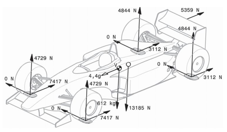
As you have allready mentioned in your post, the basic formula for long load transfer is:
dW = (m * h * a) / l
* with dW symbolising the total weight transfer due to an acceleration a (m/s²),
* a total vehicle mass m (in kg),
* h the height is the height of center of gravity,
* l is the wheelbase.
(borrowed from F1technical

)
and you have allready mentioned that a change in CoG height will affect the load transfer.
IMHO the change of CoG height during braking, is a secondary effect when we talk about an F1 car, but it´s there.
Other secondary effects (IMHO) you could consider are
- change in wheelbase, due to kinematic effects (and/or steering input in combined cornering/braking situations)
- movement of fuel inside the tank, both in terms of change in CoG height and for/aft weight distribution
- change in loaded tire radius, both in terms of CoG height and momentum arm for brake torque
other factors worth to keep in mind.
- change in CoF in the brake pads due to temperature and rotational speed changes.
- stiffness of the brake system (flex in the system)
- temperature effects on the stiffness of components (think brake caliper flex and the ban of MMC for brake calipers)
- compressibility of hydraulic fluid in relation to temperature (boiling point)
- hysteresis in the brake system
- effect on aerodynamic drag on overall braking performance (low speed vs. high speed braking) - not transmitted via the tires.
- effect of downforce related vertical load in terms of possible brake force distribution ( high vs. low speed braking, --> higher speed --> higher DF--> enables higher long. G (decceleration). higher decceleration (log.G) means more load transfer towards the front
- effect of track inclination on braking performance (uphill vs. downhill braking)
--> change in track inclination in the braking zone (braking over a crest)
- effect of head or tail wind (at different parts of the track)
So long post - sorry mods
maybe some food for thought for your project
I think you should differenciate between fixed brake bias (but maybe changed for different corners (low speed vs. high speed)), adjustments such as balance bar position
and full dynamic brake bias changes, which alter the bias "automatic" depending from different parameters.
IMHO - the first step would be to calculate the optimum brake bias for different conditions (brake force parabel) and then look a possible ways to achieve it, or to come as close as possible towards it.
Here, we may need to consider limitation which are imposed by the technical reglement, such as ban of electronic &/or active systems, or the condition that the brake pressure left vs. right in one circuit needs to be equal.