2 stroke thread (with occasional F1 relevance!)

All that has to do with the power train, gearbox, clutch, fuels and lubricants, etc. Generally the mechanical side of Formula One.
manolis
manolis
107
Joined: 18 Mar 2014, 10:00

Re: 2 stroke thread (with occasional F1 relevance!)

Post

Hello J.A.W.

You write:
“Hi Manolis, why would a supercharged 2T PatRoVa be any more "complicated & expensive " - than if built as a 4T?
If every piston down-stoke is a power-stroke, & the PatRoVa head can deliver the required gas flow, then 'what's not to like?'”

Because with a PatRoVa cylinder head the 4-stroke gets not only better but also way simpler.

Either we talk for big, expensive and technologically advanced engines like the Ducati Desmodromic Panigale (here is its horizontal cylinder head exploded):

Image

or we talk for small, push-rod engines like the fs56 4-stroke of OS for model airplanes:

Image

The valve train parts are in red ellipses:
Restoring springs, rocker arms and pivot shaft in the top left ellipse.
The intake and the exhaust poppet valves in the next ellipse.
Push rods and covers and seals and cam followers in the next ellipse.
Camshaft and bearings in the bottom ellipse.

All these parts for a 10cc single cylinder engine with peak power at 10,000rpm and red line at only 13,000rpm (9m/sec mean piston speed).

By replacing all these parts by a PatRoVa spool, the engine gets way simpler, the red line goes to, say, 30,000rpm, the power multiplies, etc.

By the way, does anybody know what is the red line of the 4-stroke model engines?
Is it limited by the valve train?

At http://www.pattakon.com/tempman/osmz211 ... cnitro.pdf it is the dyno test of the OS .18z 2-stroke model engine (750PS/lit) of the same company (OS) with rev limit above 40,000+ rpm (mean piston speed above 20m/sec).
Think of the size of a PatRoVa rotary valve for a 16mm bore model engine.


In comparison to the previous, with PatRoVa rotary valves in the cylinder head and an external supercharger driven by the crankshaft, a port-less 2-stroke gets complicated and expensive, being inferior than the 4-stroke as regards emissions (unless it is a Diesel) and load control (partial load operation, flat torque etc).

On the other hand, for Diesel engines, i.e. for engines based on the lean burn like the experimental 2-cylinder 2-stroke of Renault:

Image

the use of high revving valves (like the PatRoVa rotary valves) is an obvious advantage and necessity.

Thanks
Manolis Pattakos

Brian Coat
Brian Coat
99
Joined: 16 Jun 2012, 18:42

Re: 2 stroke thread (with occasional F1 relevance!)

Post

Tiny 4 stroke rpm limit?

I'd expect valve gear as the rpm limit but the squared-cubed effect of tiny cylinders as the performance limit.

Then as now, development time counts for a lot.

E.g. Honda could run their RC148 to over 22,000 rpm (20.1 m/s MPS) reliably in 1965 (cylinder size about 25 cc) but when the Cosworth DFV made its debut in 1967, it was limited to 9000 rpm (19.5 m/s MPS) due to valve gear vibration issues (cylinder size 15x Honda RC148 at about 375cc).

Despite all this brilliant work from Honda, the two strokes became dominant.

(Edited in line with Manolis error spotting)
Last edited by Brian Coat on 18 Jun 2016, 16:47, edited 1 time in total.

J.A.W.
J.A.W.
109
Joined: 01 Sep 2014, 05:10
Location: Altair IV.

Re: 2 stroke thread (with occasional F1 relevance!)

Post

Hi Manolis, I think you misunderstand my meaning..

If the PatRoVa head is free from poppet valve rpm/gas flow timing constraints, then why bother with it at all, as a '1/2 time work 4T?
If the PatRoVa is suitable for function as a uniflow externally scavenged (S/C'd) 2T, free from the concerns of ports cut through sleeves?
"Well, we knocked the bastard off!"

Ed Hilary on being 1st to top Mt Everest,
(& 1st to do a surface traverse across Antarctica,
in good Kiwi style - riding a Massey Ferguson farm
tractor - with a few extemporised mod's to hack the task).

manolis
manolis
107
Joined: 18 Mar 2014, 10:00

Re: 2 stroke thread (with occasional F1 relevance!)

Post

Hello J.A.W.

In a PatPortLess 2-stroke engine:

Image

the cylinder head is fully covered with exhaust poppet valves; the piston crown is also fully covered with intake poppet valves.

This way the valve-time area remains, more or less, the same with that of a conventional 4-stroke with similar poppet valves in its cylinder head: the time halves (because the PatPortLess is a 2-stroke), but the valve area doubles.

This is good for Diesels, wherein the efficient combustion of the fuel sets the rev limit.
For instance, at 5,000rpm (which is more than the revs wherein a compression ignition engine provides its peak power) the poppet valves of the PatPortLess run as if they were in the cylinder head of a conventional 4-stroke engine running at about 2x5,000=10,000rpm.
Characteristic of the PatPortLess is the covering of the piston crown with intake valves and the through scavenging of the cylinder: during the scavenging all poppet valves are open simultaneously, with the fresh charge entering from the piston crown “ports” (i.e. quite differently than in a Detroit-GM engine) and with the burned gas exiting from the cylinder head “ports” (as in the Detroit/GM 2-strokes, but rid of the lubrication issues of the Detroit/GM engines).

For high revving spark ignition engines the PatPortLess architecture is not so good because the rhythm the poppet valves need to open and close gets too fast: the time for opening and closing is half than in a similar 4-stroke.


With PatRoVa rotary valves on the cylinder head, the relation of the flow capacity of the 2-stroke and of the 4-stroke versions is similar.
Suppose a pair of PatRoVa rotary valves like:

Image

is used in the cylinder head (necessarily at a substantial distance from each-other to avoid short-circuiting during the scavenging), with the one rotary valve controlling the exhaust and with the other rotary valve controlling the transfer/inlet.

If both rotary valves (the exhaust rotary valve and the transfer/inlet rotary valve) of the above 2-stroke were used for the breathing of the 4-stroke, the flow capacity of the 2-stroke would be half than the flow capacity of the 4-stroke (same valve area, double duration).

If the underneath mechanism (pistons, connecting rods, crankshaft, casing) is robust enough to operate at really high revs, the peak power of the 2-stroke is similar to the peak power of the 4-stroke (for same capacity engines).

If the underneath mechanism sets the rev limit, then the 2-stroke makes more power than the 4-stroke (for engines of same capacity).

Unlike the PatPortLess architecture that uses / exploits both sides of the cylinder for breathing, when you have to fill and evacuate the cylinder exclusively from the cylinder head side, there is shortage of “valve area” (unless the cylinder is substantially short /over-square), which limits the peak power.

I hope it is clearer now.

Thanks
Manolis Pattakos

J.A.W.
J.A.W.
109
Joined: 01 Sep 2014, 05:10
Location: Altair IV.

Re: 2 stroke thread (with occasional F1 relevance!)

Post

Indeed Manolis, the only way an N/A 4T can even approach the work output a 2T of similar capacity, is by short-stroke/very high rpm.
& that necessitates expensive/robust but lightweight internal construction, to reliably deal with the inevitable forces required.

Alternatively, many auto-makers are now building forced induction 4Ts ( usually turbos) that use pressure & under-square
cylinders that don't require high rpm, albeit they still have to be robust constructed , & therefore heavy/bulky/costly..

If your PatRoVa can produce the work output as an externally scavenged/clean burning 2T, then it will not need to rev hard,
or be over-built, for the work it does.
"Well, we knocked the bastard off!"

Ed Hilary on being 1st to top Mt Everest,
(& 1st to do a surface traverse across Antarctica,
in good Kiwi style - riding a Massey Ferguson farm
tractor - with a few extemporised mod's to hack the task).

Tommy Cookers
Tommy Cookers
622
Joined: 17 Feb 2012, 16:55

Re: 2 stroke thread (with occasional F1 relevance!)

Post

manolis wrote:..........or we talk for small, push-rod engines like the fs56 4-stroke of OS for model airplanes:
..............By the way, does anybody know what is the red line of the 4-stroke model engines?
.............Is it limited by the valve train?
4 stroke model engines seem to be a niche of authentic/pleasant-sounding, easily managed performance matched eg to slow or scale models
usually having bearing lubrication only indirectly from the high (eg 15-20%) oil content of the fuel
and available as multis eg 2-7 cylinders

manolis
manolis
107
Joined: 18 Mar 2014, 10:00

Re: 2 stroke thread (with occasional F1 relevance!)

Post

Hello Brian Coat.

You write:
“E.g. Honda could run their RC148 to over 22,000 rpm (>21 m/s MPS?) reliably in 1965 (cylinder size about 25 cc) but when the Cosworth DFV made its debut in 1967, it was limited to 9000 rpm (well under 20 m/s MPS?) due to valve gear vibration issues (cylinder size 15x Honda RC148 at about 375cc).”


The piston stroke of the Honda RC148 is 27.4mm (0.0274m), which means that at 22,000rpm of the peak power the mean piston speed is:

0.0274 * 2 * ( 22,000/60 ) = 20m/sec.


The piston stroke of the Cosworth DFV is 65mm (0.065m), which means that at 9,000rpm of the peak power the mean piston speed is:

0.065 * 2 * ( 9,000 / 60 ) = 19.5m/sec, i.e. just under 20m/sec.


The modified to VVA-roller B16A2 VTEC 1600cc Honda engine

Image

(more at http://www.pattakon.com/pattakonRoller.htm and http://www.pattakon.com/pattakonVtec.htm )
has 77.4mm piston stroke.
At 9,000rpm wherein the rev limiter is set, the mean piston speed is:

0.0774 * 2 * ( 9,000 / 60 ) = 23m/sec

and it is not a racing engine (the underneath parts are normal Honda).


Hello Tommy Cookers.

For an RC (radio controlled) model engine (like the 10cc OS fs-156 of OS for model airplanes) the low mean piston speed means low peak power and low power to weight ratio. The push rods in the valve train limit the revs. The poppet valves with their restoring springs also limit the revs.

What about a, say, 3cc 4-stroke PatRoVa RC/model engine (say 15mm stroke, 16mm bore) making its peak power at, say, 50,000rpm? (wherein the mean piston speed is 25m.sec)

Thanks
Manolis Pattakos

Brian Coat
Brian Coat
99
Joined: 16 Jun 2012, 18:42

Re: 2 stroke thread (with occasional F1 relevance!)

Post

Manolis, you're right. Sorry for the error and thanks for pointing it out. I lifted the bore and stroke from the wrong 25cc/pot Honda race engine.

None-the-less your corrected data still illustrates the point about development being a real world limitation: highly developed tiny cylinder race engine "out-MPS's" an excellent but undeveloped engine with order-of-magnitude bigger cylinders.

You mentioned rotary valve 4T model engine and you can get them, like this but they don't rev very high:

http://www.rcvengines.com/rcv58cd.htm

Tommy Cookers
Tommy Cookers
622
Joined: 17 Feb 2012, 16:55

Re: 2 stroke thread (with occasional F1 relevance!)

Post

manolis wrote:The conventional Radials have more significant problems than the firing order.
Quote from http://www.pattakon.com/pattakonPatAT.htm
In comparison to the convetional Radial engine:
http://www.pattakon.com/PatAT/Radial_Cam_Anim.gif
As the Radial.exe demonstrates, a typical Radial (master rod / slave rods) cannot help running with substantially different piston strokes in different cylinders.”
End of Quote.
More important than the uneven firing is the uneven way the various cylinders of a conventional Radial operate. With the master cylinder arranged at the top of the conventional Radial engine, the pistons in the “side” cylinders perform a stroke of about 10% longer than the stroke of the piston in the “master cylinder”, with the cylinders at the one side compressing substantially faster and with the cylinders at the other side expanding substantially faster.
the Exe was not a conventional radial (even stroked or not)

in the conventional radial all the piston motions have the same stroke
because the slave rod pin angle (at the main pin axis, subtended from the master rod centreline) is equal to the angle between cylinder axes
according to C Fayette Taylor's 'The Internal Combustion Engine - Theory and Practice' - Vol 2 Chapter 8 'engine balance and vibration'

in the representation of the conventional (albeit 11 cylinder) radial provided on p 57 the slave rod big end centres seem unevenly spaced
can that be correct ?

wuzak
wuzak
447
Joined: 30 Aug 2011, 03:26

Re: 2 stroke thread (with occasional F1 relevance!)

Post

Tommy Cookers wrote:in the conventional radial all the piston motions have the same stroke because the slave rod pin angle (at the main pin axis, subtended from the master rod centreline) is equal to the angle between cylinder axes according to C Fayette Taylor's 'The Internal Combustion Engine - Theory and Practice' - Vol 2 Chapter 8 'engine balance and vibration'
I don't think that is correct Tommy, as the angle at which the master rod is affects the relationship between the slave rod big end and the crankshaft journal.

For all the slave rods to have the same stroke they would need to have the same relationship between the big end of the slave rod, the crankshaft journal and the centreline of that particular cylinder at both TDC and BDC.

From memory, and it's been a while since I looked at this, the slave rod big end can be lined up with the bore CL and the journal at TDC but won't be at BDC, and it will be different for each cylinder.

Also, if it worked for 5. 7. 9 or 11 cylinders, why wouldn't it work for 4?

Tommy Cookers wrote:in the representation of the conventional (albeit 11 cylinder) radial provided on p 57 the slave rod big end centres seem unevenly spaced can that be correct ?
Yes, I believe hat to be correct.

The slave rod big ends will be aligned with the journal and cylinder centreline at TDC. The position of this will depend on the angle of the master rod, which is different for each cylinder.

For the slave rod big ends to be equally spaced the master rod would have to remain in the same orientation. This could be achieved with an infinitely long master rod, which is far from practical, or to use a "true motion device". I think we had such a device earlier in this thread, where there was, in fact, no master rod, but a hub (can't think of a better word) which was geared so that it did not rotate relative to the crankcase and to which the slave rods of all cylinders attached.

wuzak
wuzak
447
Joined: 30 Aug 2011, 03:26

Re: 2 stroke thread (with occasional F1 relevance!)

Post

Hard to see the relationships in Manolis' animation

Image

manolis
manolis
107
Joined: 18 Mar 2014, 10:00

Re: 2 stroke thread (with occasional F1 relevance!)

Post

Hello Tommy Cookers.

You write:
“in the conventional radial all the piston motions have the same stroke
because the slave rod pin angle (at the main pin axis, subtended from the master rod centreline) is equal to the angle between cylinder axes
according to C Fayette Taylor's 'The Internal Combustion Engine - Theory and Practice' - Vol 2 Chapter 8 'engine balance and vibration'”


A couple of pages later, Taylor continuous the balance analysis of the Radial engines with the evenly spaced hinge-pins:
“the only serious unbalance in a conventional single row radial engine is a second order force, which can be represented by a constant vector leading the crank by 180 degrees at top center of the master-rod cylinder and revolving at twice crank speed in the direction of the crank rotation.
In large radial engines this force is often balanced by fore-and-aft weights revolving about the crankshaft axis at twice engine speed.”

The arrangement in Taylor’s Book reduces the difference between the strokes of the pistons in a row of cylinders in expense of another unevenness – irregularity: the pistons may have almost equal strokes, but they arrive at their TDC at angles which differ from the theoretically correct ones.

Here is the arrangement mentioned in Taylor book for a 4-cylinder Radial:

Image

At left is the master rod (the blue cross) with the green, purple and blue hinge-pins at its big-end side. The angles of the pins are according Taylor’s book.

At right it is shown the position of the master rod per 5 crank degrees.

The green hinge-pin of the master rod, wherein the slave rod of the left-side piston is pivotally mounted, moves around the periphery of a more or less ellipse.
The stroke of the left side piston is a little longer than the stroke of the master piston, but this is not a significant problem.
A problem is the inclination of the slave connecting rod (red) when the left side piston is at its TDC.
Worse is that the TDC of the side cylinders are not spaced 90 crank degrees before and after the TDC of the master piston.

This arrangement introduces an unevenness – irregularity in the crank angles the pistons arrive at their TDC (like, say, 0, 98, 180, 262 crank degrees, instead of the correct: 0, 90, 180, 270).

In the conventional Radials with pushrods / poppet valves, a disk with several identical camlobes on its periphery and rotating several times more slowly than the crankshaft (see the animation in Wuzak’s post), actuates the poppet valves of all cylinders. When the pistons arrive at their TDC not in the correct crank angles, the common multi-cam-disk becomes another serious compromise: depending on the cylinder, the valve overlap happens either symmetrically about the piston TDC (master piston, “bottom” piston) or substantially before the specific piston TDC (left-side pistons) or substantially after the specific piston TDC (right-side pistons).


Here is a different than Taylor’s arrangement wherein the hinge-pins are disposed at different / uneven angles:

Image

The pins on the master rod whereon the slave rods are pivotally mounted are not distributed equally. The hinge-pins towards the small end of the master rod are disposed at bigger angular distances relative to the hinge-pins away from the master-rod small end.

The side pistons have substantially longer stroke, however the pistons arrive at their TDC at even crank angles (like: 0, 90, 180 and 270 in the four-cylinder radial).


Quote from http://www.pattakon.com/tempman/Radial_ ... _Slave.pdf

Kinematic Relations Between Master and Slave Cylinders in Radial Engines
Carl D. Sorensen
Department of Mechanical Engineering
Brigham Young University
Provo, Utah 84602
January 22, 2008

. . .

To date, I have been able to get the TDC position and stroke length errors
to be very close to zero, but with variable TDC timing.
I have also been able to get the TDC position and TDC timing to be equal,
but with variable stroke.
I have not been able to get TDC position, stroke, and TDC timing errors all
to be very close to zero simultaneously.

End of quote.


Either the arrangement in Taylor’s book (evenly spaced hinge-pins) or the most common (?) arrangement with the unevenly spaced hinge-pins (which leads to evenly spaced TDCs) are significantly problematic as regards two important issues.
The one issue is the vibration-free quality: think of am 11-cylinder Radial having a significant 2nd order rotating unbalanced inertia force loading the frame of an airplane; in comparison, a conventional six in line is fully balanced as regards inertia forces and moments.
The other issue is the unevenness – irregularity of the piston motion profiles. Look at the drawing with the path of the various hinge-pins and think how much differently the pistons move. Also see the unevenness between the leaning of the slave connecting rods: the “bottom” slave rod leaning angle is way bigger (the same for the thrust loads on the cylinder liner) than the leaning angle of the master rod and than the leaning angles of the side slave rods. Worse even, depending on the side wherein the specific cylinder is arranged, the leaning of the slave rod is way bigger before the TDC or after the TDC of the specific cylinder.


I think that after the previous analysis it is time to take another look at the PatAT Radial which with only four cylinders (and its forked connecting rods):

Image

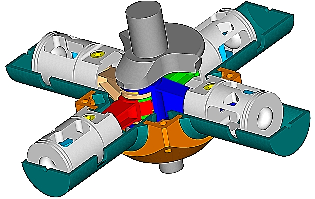
is a by far more symmetrical design than any conventional Radial (either with Talor’s arrangement or with the uneven spaced hinge-pins arrangement) no matter how many cylinders the conventional radial comprises.

Besides, among the characteristics of the PatAT 2-stroke Cross-Radial is also the asymmetric transfer (as asymmetric as in the famous Opposed Piston engines, but without the side-effects the asymmetric timing causes in the OP engines) and “4-stroke like” lubrication (more at http://www.pattakon.com/pattakonPatAT.htm )

Thanks
Manolis Pattakos

manolis
manolis
107
Joined: 18 Mar 2014, 10:00

Re: 2 stroke thread (with occasional F1 relevance!)

Post

Hello Wuzak.

You write:
"Hard to see the relationship in Manolis' animation"

With the cylinders equally spaced around the rotation axis of the crankshaft, according the arrangement in Taylor's book the hinge-pins should be evenly spaced around the center of the big-end of the master-rod (which obviously is not the case in the animation: the lower hinge-pins are closer to each other).

With evenly spaced cylinders and evenly spaced hinge-pins (Taylor), the pistons have almost equal strokes, but they arrive at their TDC at uneven crank angles.

Thanks
Manolis Pattakos

manolis
manolis
107
Joined: 18 Mar 2014, 10:00

Re: 2 stroke thread (with occasional F1 relevance!)

Post

Hello Brian Coat.

In the RCV58CD link the specifications are no better than in the poppet valve RC 4-stroke engines (like the 9.5cc OS).

With 0.85bhp (0.64kW) from 9.5cc, the specific power is too low (90PS/lit).

In comparison, the OS.18TZ 2-stroke (3cc) makes 750PS/lit.

Thanks
Manolis Pattakos.

Tommy Cookers
Tommy Cookers
622
Joined: 17 Feb 2012, 16:55

Re: 2 stroke thread (with occasional F1 relevance!)

Post

@ manolis
many thanks regarding information you posted 4.46 today on slave rod pin disposition around the crankpin centre - eg whether equal or unequal .....

the example pictured is from a model of a Bristol Aquila - the first Bristol sleeve valve, 1933 or so
presumably, with sleeve valves equalisation of some parts of piston motion was particularly desired (and might explain the unequal disposition shown)
fwiw it's not clear to me from eg rather poor pictures of P&W master rods whether or not they had equal disposition
as they and their plagiarists made about 1 million master rods it's inconvenient that I can't find a useful picture of these or eg Wright
or of the Bristol Jupiter, the first radial to make a real impact

machine theory books, irritatingly focus on radials with rods all on 1 crankpin
presumably this is related to some prevelance of stationary radial machinery eg pneumatic and hydraulic pumps and motors
3 cylinders a significant number re self-starting, anyway the low rpm and stresses would allow multiple rods per crankpin configuration


CWT's book confirms that a big issue with aero engines is crankshaft torsional vibration, its sensitivity to and interaction with propellor/rotor vibration
unavoidable, due to the impulsive combustion contributing an impulsive torque to the crankshaft
most aircraft have no-go rpm bands for this reason
and even when there's ideal balance of piston motion giving eg broadly zero vibration there's torsional vibration on the airframe
as shown eg by the 4.5th and 6th order dampers in the conventional flat 6

of course as I said, the closer (2 stroke) firing intervals seem rather helpful with your cross 4 (though one might imagine the CI isn't)