2014 front wing endplate design

Here are our CFD links and discussions about aerodynamics, suspension, driver safety and tyres. Please stick to F1 on this forum.
rjsa
rjsa
51
Joined: 02 Mar 2007, 03:01

Re: 2014 front wing endplate design

Post

bhallg2k wrote: I think endplates next year might look something like this, only a bit thinner to conform to the allowed dimensions:

http://i.imgur.com/lvKIrET.jpg

Blanchimont's split-endplate idea, a la Mercedes, makes a lot of sense, too.

You just cut the endplate horizontally along the flap line and make the lower part pointing outards and that'll be my guess.

EDIT: Somthing like this rough I did here:
Image

Huntresa
Huntresa
54
Joined: 03 Dec 2011, 11:33

Re: 2014 front wing endplate design

Post

rjsa wrote:
bhallg2k wrote: I think endplates next year might look something like this, only a bit thinner to conform to the allowed dimensions:

http://i.imgur.com/lvKIrET.jpg

Blanchimont's split-endplate idea, a la Mercedes, makes a lot of sense, too.

You just cut the endplate horizontally along the flap line and make the lower part pointing outards and that'll be my guess.

EDIT: Somthing like this rough I did here:
http://farm9.staticflickr.com/8529/8623 ... 20cb_b.jpg
With that couldnt you also curve a 4th or 5th element to create a tunnel redirecting air to the inside of the tyre, like the tunnel that Sauber is running if you look from behind or from the underside of their current wing.

rjsa
rjsa
51
Joined: 02 Mar 2007, 03:01

Re: 2014 front wing endplate design

Post

You mean this?
Image

It's just creating a ventury between the extra element and the endplate, it does not go inboard enough to clear the airflow from the wheel.

You don't want to chocke the flown under the wing, where you want fast low pressure air flow. You can chocke it above the wing, where you want slower, highier pressure flow.

TryHard
TryHard
9
Joined: 13 Jan 2004, 11:46

Re: 2014 front wing endplate design

Post

Having been looking hard at the wings, and do some of my own cad work on a version some sections, I'm still of the opinion that a full blown inwash wing probably won't be the best solution, as it will also be very tricky to fit in the rules boxes (as already mentioned), and the reduction of downforce generating area will be an issue, not to mention that some extreme angles will be needed.

I've mocked up the front end as part of a project I'm doing, so thought I'll post up some thoughts.

Image
Image

The red lines represent all the rules boxes, as outlined in Balchimonts post previously. Purple section in the middle is the mandated section. Green shape box is the no bodywork zone as defined in section 3.11 of the regs. Oh, and Blue is the wheel/tyre :p

Now, to help distinguish the point I'm trying to make, the Purple section of the endplate vane is the minimum legal size that the endplate can be (95,000mm2 / 275mm high = 345.45mm long... all in side view). So basically, if you use an endplate in the box, it has through the point where the purple and orange sections meet (that intersection is 345.45mm back from the front edge of the box). Obviously, what you do with the endplate in the box in terms of planar shape doesn't really matter, but to keep the intersection at that point, it would have to be full height along it's length (comes back to the area rule). The orange curve could be smoother I admit, but it's still a steep shape change to get to the inside of the tyre, and your chocking off the underside...

I think something along the lines of what Blanchimont proposed sounds most fesable, with the outer sections being outwashed as best as possible (maybe run the actual wing sections out as wide as possible, and mount the endplate on top of curved down wings, much like some teams already do), and an inner set of vanes to best direct the airflow off the wing sections inside the inner tire sidewall, without shutting off airflow. In effect creating a three division front wing, all with different wing parts and so on...
1) Mandated centre section
2) Inner tire section
3) Outer section

Rjsa's idea also works as it would meet the dimension regs, and not have the chocking underflow... more I look at it the more I understand it, just wonder if you couldn't do similar with curved down wings and vanes instead..

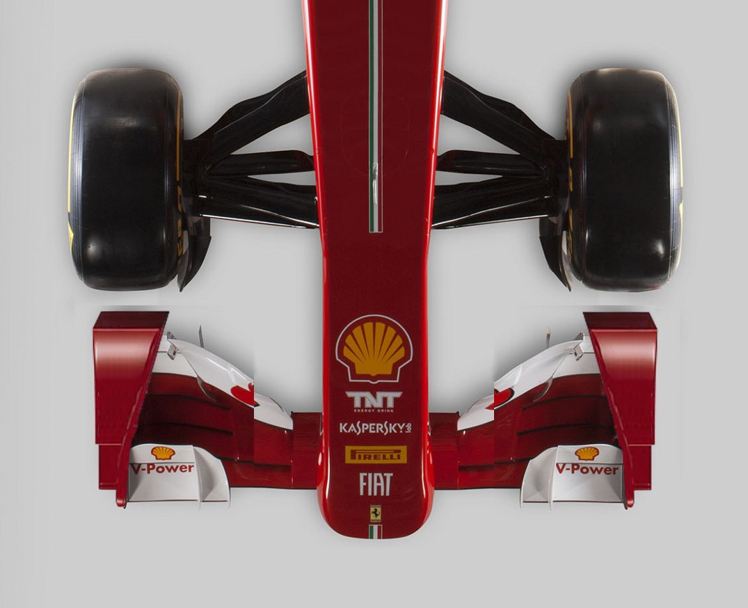
Maybe the current trend for lots of multi planes on the outer sections (I think Ferrari has 7 on the outer ends of their current wing!) will move more towards the middle of the wing, working in the smoother airflow inside the tyre, with less on the outer sections to help reduce sensitivy to tyre interference? Who knows... only 8 months to wait! :lol: :lol:

Regards
Ed

Huntresa
Huntresa
54
Joined: 03 Dec 2011, 11:33

Re: 2014 front wing endplate design

Post

I was looking at the World Series By Renault 3.5 race today and it struck me that they pretty much have the same endplate area as F1 will have next year, as in its placed almost at the center infront of the wheel.

Image

However their wingdesign doesnt seem to do anything else then stop the air in its track since the back of the endplate seems to be 90degrees and just act as a wall, going somewat outwards i guess.

rjsa
rjsa
51
Joined: 02 Mar 2007, 03:01

Re: 2014 front wing endplate design

Post

That's how the endplates started for the current wings, it didn't last much though.
Image

Huntresa
Huntresa
54
Joined: 03 Dec 2011, 11:33

Re: 2014 front wing endplate design

Post

rjsa wrote:That's how the endplates started for the current wings, it didn't last much though.
http://i.cdn.turner.com/cnn/2009/SPORT/ ... SAUBER.jpg
Yeah but what i meant was that they arent full lenght not what they actually do.

bhall
bhall
244
Joined: 28 Feb 2006, 21:26

Re: 2014 front wing endplate design

Post

TryHard wrote:Having been looking hard at the wings, and do some of my own cad work on a version some sections, I'm still of the opinion that a full blown inwash wing probably won't be the best solution, as it will also be very tricky to fit in the rules boxes (as already mentioned), and the reduction of downforce generating area will be an issue, not to mention that some extreme angles will be needed.

[...]
Most downforce is produced near the leading edge of the wing, and an outwash design would inherently limit that area. That's an acceptable tradeoff given the current wingspan and its ability to reduce drag associated with the wheels, which is as much as 40% of total drag on the car. I don't believe that will be possible next year with endplates that are centered in front of the wheels.

Image
Williams FW31

Additionally, the front wing experiences a greater loss of downforce mid-span than it does at the tips when following another car. Remember, that was the pretty much the entire rationale behind the current aerodynamic formula. So, it makes little sense to me to reduce the area of the wing that creates the most consistent downforce with an outwash endplate that's been purposely neutered by the regulations.

Image
(The full text of this report can be found here.)

No matter how they're configured, I think next year's endplates will represent a net loss of performance compared to current designs. The trick will be to choose the lesser evil. The blown hub design used by Red Bull last year, and to a greater extent by Williams this year, shows us that wheel wake can be addressed with a solution that uses airflow sourced between the wheels.
John Axerio-Cilies and Gianluca Iaccarino, Stanford University wrote:The wake behind both stationary and rotating tires is dominated by two strong counterrotating vortices. Experimental observations and numerical simulations have shown that one vortex may become stronger thus altering the wake dynamics and stability. The objective of this study is to investigate the main causes of near-wake and far-wake asymmetry. Factors such as tire camber angle, hub cavities, spoke geometry and the flow through the brake system, are all investigated as possible sources of asymmetry; it is shown that the most critical factor in flow asymmetry is the flow through the hub of the tire. When this is primarily in one direction (inboard to outboard side), the inboard vortex increases in size and intensity, eventually overwhelming the outboard vortex.
Image
Left: airflow around a rotating wheel without transverse flow through the hub/wheel. Right: airflow around a rotating wheel with transverse flow through the hub/wheel.

User avatar
hollus
Moderator
Joined: 29 Mar 2009, 01:21
Location: Copenhagen, Denmark

Re: 2014 front wing endplate design

Post

I'd challenge the notion that endplates are there to reduce drag from the wheels, it just looks like that because we mostly see front wings from above and from the front and air appears to be physically pushed away by the endplate. There is air also on the inside face of the end plate, there is air also below the front wing's plane; it is not like one can put the wheel in a partial vacuum.

I think inbound end plates are there more to protect (most of) the wing from the tire's influence than to protect the tire from the wing, while outbound endplates are largely about conditioning the air for the rest of the car.
What most people did pre-2009, see Macca below (Edit: with grooved tires and zillions of winglets, clearly 2008 and not 2009, thanks Huntresa!)) was to keep the working part of the wing in clean air. Edit 2: here it said something about Brawn that proves that I was talking out of my a## and that one should check old car pictures before letting words out.
The above is my opinion only and not based on any hard numbers or calculations.
Image
Last edited by hollus on 07 Apr 2013, 19:30, edited 3 times in total.
Rivals, not enemies.

bhall
bhall
244
Joined: 28 Feb 2006, 21:26

Re: 2014 front wing endplate design

Post

Martinus van den Berg wrote:The complicated endplate shapes that are being used on current F1 cars show that the constructors are constantly looking for gains resulting from the interaction of wing and wheel flow. However some of the design changes are made quite ad hoc and the physical principles behind them are not always understood. Furthermore, with the exception of using two smaller instead of one normal size wheel, not much can be done to limit the wheel drag directly. However when the relative wing position and the wing endplate design are taken into consideration as well, it is very well possible to reduce the wheel drag indirectly.
Van den Berg's thesis is a looooooooooong read, but contains tons of useful information.

EDIT:
hollus wrote:[...]
Edit 2: here it said something about Brawn that proves that I was talking out of my a## and that one should check old car pictures before letting words out.
[...]
The language of my people. :)
Last edited by bhall on 07 Apr 2013, 20:05, edited 1 time in total.

Huntresa
Huntresa
54
Joined: 03 Dec 2011, 11:33

Re: 2014 front wing endplate design

Post

hollus wrote:I'd challenge the notion that endplates are there to reduce drag from the wheels, it just looks like that because we mostly see front wings from above and from the front and air appears to be physically pushed away by the endplate. There is air also on the inside face of the end plate, there is air also below the front wing's plane; it is not like one can put the wheel in a partial vacuum.

I think inbound end plates are there more to protect (most of) the wing from the tire's influence than to protect the tire from the wing, while outbound endplates are largely about conditioning the air for the rest of the car.
What most people tried to do in 2009 (see Macca below) was to keep the working part of the wing in clean air, Brawn found out that it was better to have more working plane area even if it meant using dirtier air.
The above is my opinion only and not based on any hard numbers or calculations.
http://www.grandprix.com/jpeg/misc/mcla ... ch1-lg.jpg
If im not totally wrong that isnt 2009 macca, its 07 or 08, a comparison.

Image

User avatar
raymondu999
54
Joined: 04 Feb 2010, 07:31

Re: 2014 front wing endplate design

Post

Huntresa wrote:
hollus wrote:I'd challenge the notion that endplates are there to reduce drag from the wheels, it just looks like that because we mostly see front wings from above and from the front and air appears to be physically pushed away by the endplate. There is air also on the inside face of the end plate, there is air also below the front wing's plane; it is not like one can put the wheel in a partial vacuum.

I think inbound end plates are there more to protect (most of) the wing from the tire's influence than to protect the tire from the wing, while outbound endplates are largely about conditioning the air for the rest of the car.
What most people tried to do in 2009 (see Macca below) was to keep the working part of the wing in clean air, Brawn found out that it was better to have more working plane area even if it meant using dirtier air.
The above is my opinion only and not based on any hard numbers or calculations.
http://www.grandprix.com/jpeg/misc/mcla ... ch1-lg.jpg
If im not totally wrong that isnt 2009 macca, its 07 or 08, a comparison.

http://www.f1fanatic.co.uk/wp-content/u ... _mp423.jpg
You're correct Huntresa. That's Kovalainen's 2008 car, as denoted by the car number 23. (Hamilton had car 22)
失败者找理由,成功者找方法

User avatar
Blackout
1563
Joined: 09 Feb 2010, 04:12

Re: 2014 front wing endplate design

Post

R29 FW endplates were 'inwash' AND 'outwash' at the same time. IMO it's a very interesting design for 2014, more interesting than 2009 hence the '14 FW are less wide and let you center the endplate in front of the wheel...

Edit: I just read the previous interesting posts :oops:

R29 endplates on bhallg2k's photoshop
Image

http://www.formula1.com/wi/full/ta_arti ... le_625.jpg

astracrazy
astracrazy
31
Joined: 04 Mar 2009, 16:04

Re: 2014 front wing endplate design

Post

i'm pretty sure your image is wrong as it doesn't meet the two regulations for the minimum endplate area size in side view. i may be wrong but it doesn't look like it does.

i've looked at this before and the angle of the endplate inwards is going to be much less (to meet with the regs within the two areas) with a sharp curve towards the tyre once these have been met

Huntresa
Huntresa
54
Joined: 03 Dec 2011, 11:33

Re: 2014 front wing endplate design

Post

astracrazy wrote:i'm pretty sure your image is wrong as it doesn't meet the two regulations for the minimum endplate area size in side view. i may be wrong but it doesn't look like it does.

i've looked at this before and the angle of the endplate inwards is going to be much less (to meet with the regs within the two areas) with a sharp curve towards the tyre once these have been met

Its the Renault 2009 endplates so it should be OK with the regulations.