TalnoRacing wrote:This has been a very educational thread, thank you to those openly sharing information.
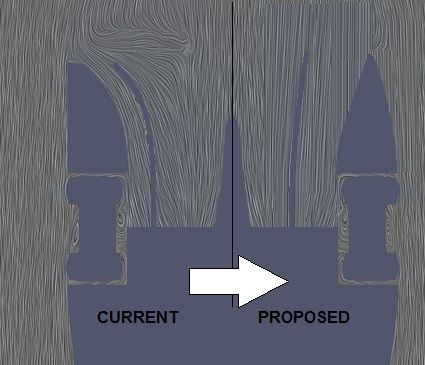
Can someone please advise which Paraview settings are used to generate the image below? I am using version 3.98.0 and I have not been able to generate this type of view.
-Make sure SurfaceLIC is loaded (only need to do this once): go to tools -> manage plugins and expand the "SurfaceLIC" entry. Tick the 'auto load' box. You may need to restart Paraview. If you open the plugin manager again you should now see "Loaded" next to "SurfaceLIC".
-Open the case in Paraview. In the properties panel, tick 'internalMesh' and nothing else in the top panel, and 'U' and 'P' in the bottom panel, then click apply. After it's loaded, you should see a box.
-In the top toolbar, click the 'slice' button and click apply. You can position it before clicking apply, or re-position it later. You should now see a plane, probably coloured by pressure depending on your defaults.
-In the top toolbar, there should be a dropdown displaying "Surface". Change this to "SurfaceLIC". You should hopefully see some streamlines, but they will probably be invalid, all flowing in one direction.
-In the properties panel, look for the "SurfaceLIC: Integrator" subsection. The first element there should be a dropdown called "Vectors". In this dropdown there should be two "U" options with different icons. One of them should show the valid streamlines (the one with the small circular icon).
-At this point you now hopefully have the streamlines. You can play around with the other options in the properties panel, such as "Colour Mode" and "Enhance Contrast" to make it a bit easier to see the colours. You can also re-position the plane (top of the properties panel) to inspect different areas of the car). You can change which scalar field the colours are showing with the other dropdown in the top toolbar - you will probably need to tweak the range by using the range controls in the top toolbar.