Nose cone idea

Here are our CFD links and discussions about aerodynamics, suspension, driver safety and tyres. Please stick to F1 on this forum.
shawness
shawness
0
Joined: 10 Jan 2008, 15:11

Re: Nose cone idea

Post

The four-way cut would be absolutely terrible aerodynamically and would only generate a lot of turbulence. It would also weigh a lot more than a regular nose because of the strength required in the four support 'stalks' to pass a crash test and prevent the load on the front wing flexing the whole assembly.

Belatti
Belatti
33
Joined: 10 Jul 2007, 21:48
Location: Argentina

Re: Nose cone idea

Post

manchild wrote:
Belatti wrote:why did MC used a Ferrari photo to illustrate his idea? :-k :lol:
Because the topic was revived by several posts that mentioned gossips about Ferrari testing it on F2008.

How come you didn't ask "why did Ferrari used MC's drawing to experiment with this idea"? :lol:
Ups! :oops: question answered!
However I think that it would be tested only if CDF tests show something.
Could then some of our Forum CDF experts model at least two versions of MC NC and compare it with a standard one?
"You need great passion, because everything you do with great pleasure, you do well." -Juan Manuel Fangio

"I have no idols. I admire work, dedication and competence." -Ayrton Senna

User avatar
johny
0
Joined: 07 Apr 2005, 09:06
Location: Spain

Re: Nose cone idea

Post

Wow, manchild in some spanish forums they've taken your r26 concept nose sketch to say that r28 nose will be that way :D . They really trust in you

manchild
manchild
12
Joined: 03 Jun 2005, 10:54

Re: Nose cone idea

Post

johny wrote:Wow, manchild in some spanish forums they've taken your r26 concept nose sketch to say that r28 nose will be that way :D . They really trust in you
Nah... that just shows how unreliable source of information internet is. I've also read on one Ferrari forum that Renault had already experimented with such nose in 2007 simply because people saw my pic of R27 a while ago. That R27 modified photo was done quickly without any quality at all! I still don't get how people bought it when it wasn't even done and meant to be presented as fake pic in order to deceive!

On autosport forum one guy who saw my idea applied on pics of F2008 wrote "But it's only photoshop, isn't it?".

That "isn't it" is probably the best formulated compliment I ever got. :wink:

Belatti
Belatti
33
Joined: 10 Jul 2007, 21:48
Location: Argentina

Re: Nose cone idea

Post

MC, the Forum´s photoshop master!
You could earn lots of money modifiying photos of grown up celebrities for gossip magazines! :lol: :lol: :lol:
"You need great passion, because everything you do with great pleasure, you do well." -Juan Manuel Fangio

"I have no idols. I admire work, dedication and competence." -Ayrton Senna

manchild
manchild
12
Joined: 03 Jun 2005, 10:54

Re: Nose cone idea

Post

One guy on autosport forum after seeing pics I made...
Quite supicious that they have some studio pictures taken only to show of some technical detail.
:lol: :lol: :lol:

Astro1
Astro1
0
Joined: 08 Jan 2008, 21:34

Re: Nose cone idea

Post

The guy must have been using bifocals...lol

Image

modbaraban
modbaraban
0
Joined: 05 Apr 2007, 17:44
Location: Kyiv, Ukraine

Re: Nose cone idea

Post

manchild wrote:One guy on autosport forum after seeing pics I made...
Quite supicious that they have some studio pictures taken only to show of some technical detail.
:lol: :lol: :lol:
=D> :lol:

SoundMan
SoundMan
0
Joined: 08 Jan 2008, 19:41
Location: UK

Re: Nose cone idea

Post

ok, had a go at some CFD on the nose cone idea. now before i start i will say that this is the first time i have done any cfd, i only started studying it 2 weeks ago!

this was a fairly brash and rough 1st attempt to prove to myself that i could create a 3d model and then import it to do some cfd on it!


1st image, this shows the pressure distribution, blue represents lower pressure areas and therefore the locations of down force generation.
i am aware of some "errors" in the plot where for some reason some grids haven’t been calculated properly and are therefore white.

Image

it seems the extra nose slot in my example actually has higher local pressure, so would therefore not be beneficial in this case i feel. Please give me suggestions of redesign to the "nose slot" profile and i will try them again and see if it can be made to accelerate the flow. Also my front aerofoil sections are very rough i know, any suggestions there will be good too thanks.

this, the 2nd picture, shows the velocity profile around the nose. The cfd was done at 80m/s! Which is quite fast i realise, about 180mph or 288km/h.

Image

again the airflow in the "nose slot" does not accelerate, therefore i feel produces little effect.
the only thing that my be good is the reduction in "blockage" of the airflow behind the middle-rear section of the leading wing, therefore making it more effective perhaps.

interesting idea, i have some of my own, expect more soon.

until then, please give any feedback, +ve or -ve, i need to learn!

effuno
effuno
0
Joined: 13 Feb 2006, 07:43

Re: Nose cone idea

Post

first up , i think you shouldn't have done 3D analysis if there aint any change in profile in spanwise directon, and also since you haven't used any endplates! 2D would have been enough. Nevertheless, great effort and more so if you have been doing CFD only for 2 weeks. :) I haven't yet read through the results; will have to postpone that as am preparing for my exams right now :cry: ..

Thanks again :)

edit: i guess you did use the symmetry conditions ? Sorry if am insulting your intelligence (dont mean to ), but could'nt conclude on that from the pics !

manchild
manchild
12
Joined: 03 Jun 2005, 10:54

Re: Nose cone idea

Post

Thanks for trying. Apart from quite inaccurate shapes I think your CFD showed bad results due to one major thing you overlooked and that is testing these elements of nose without closing them on both sides. You can't achieve any low pressure zone by speeding up the air in Venturi zone between those elements simply because your Venturi zone lacks walls on each side. You tested extended longitudinal cross section, not the nose with aperture. Hope you understand what I'm trying to point out.

effuno
effuno
0
Joined: 13 Feb 2006, 07:43

Re: Nose cone idea

Post

for a moment i was left wondering how the front piece of nose holds to the main chassis.... a look at the front page told me that he missed it in simulation. :)

effuno
effuno
0
Joined: 13 Feb 2006, 07:43

Re: Nose cone idea

Post

between, dont you think the flow through the nose would energise the flow over the nose and thus lose some downforce ? (sorry if it has already been discussed , but 11 pages..... :roll: )

SoundMan
SoundMan
0
Joined: 08 Jan 2008, 19:41
Location: UK

Re: Nose cone idea

Post

yep effuno, that's correct. thanks manchild, i understand u. i will do my best to enclose the venturi and get some accurate aerofoil data to import also. i understand the 3d model - 2d resolution is a bit unnecessary too.

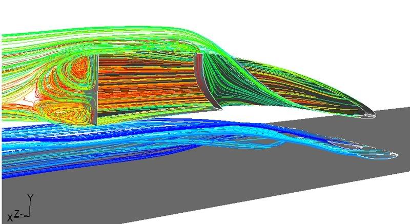
i guess i will need to resolve streamlines to get a 3d idea of whats goin on, like this:
Image

effuno
effuno
0
Joined: 13 Feb 2006, 07:43

Re: Nose cone idea

Post

yep effuno, that's correct.

i will do my best to enclose the venturi and get some accurate aerofoil data to import also. i understand the 3d model - 2d resolution is a bit unnecessary too.


You must have already realised that 3D simulations will become a necessity once you enclose the venturi. And, 'symmetry' would almost halve your calcultions and inturn, the time required.

Then again, a 2D simulation would give you a better perspective(and more accurate results) on this than a 3D without endplates and closed-venturi as there wouldnt be any tip vortices. But,obviously, once the endplates and closed-venturi(do we have a better name for this .. :roll: or is it repeatition that makes it feel wierd :o :D ) comes into play 3D is the way to go.