Wesley123's F1 Model

Post here information about your own engineering projects, including but not limited to building your own car or designing a virtual car through CAD.
wesley123
wesley123
204
Joined: 23 Feb 2008, 17:55

Re: Wesley123's F1 Model

Post

ringo wrote:
wesley123 wrote:I was just thinking about the same lol, since then the smaller wing would be in open air, I think it doesnt really makes a difference, if it is connected to the main plane it would be in front of the DRS but now it is in open air with less AoA. Too bad I am unable to do a CFD on this since it is actually a good point lol
Not really. It would still be additional drag.
I still doubt it would make a big difference, compared to the downforce you bolt on with it. I think this is the more efficient way compared to placing the wing on the main plane
What you must be careful about though, is what part is allowed to move. Though you can put anything in the middle 75mm, i think on a specific shape is allowed to move with DRS activation.

Well it is the flap that is allowed to move, this addon is just part of the wing, hence should be fully legal, of the end plates of the addon piece were connected to the main flap too to add strength then it would be illegal as then it would be a slot gap seperator which has to be 20cm apart from each other.

Per rules it would be legal, but if it was in scrutineering I think Charlie Whiting would directly ban it.
"Bite my shiny metal ass" - Bender

wesley123
wesley123
204
Joined: 23 Feb 2008, 17:55

Re: Wesley123's F1 Model

Post

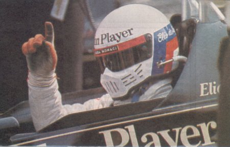
Belgium update here. Brand new front wing and rear wing, almost everything has changed

Image
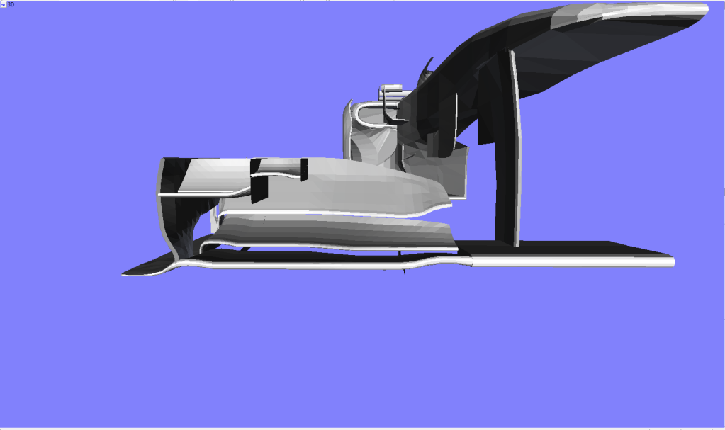
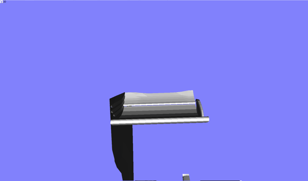
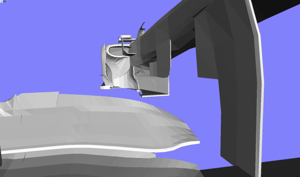
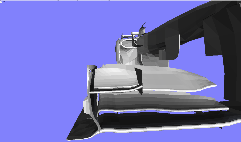
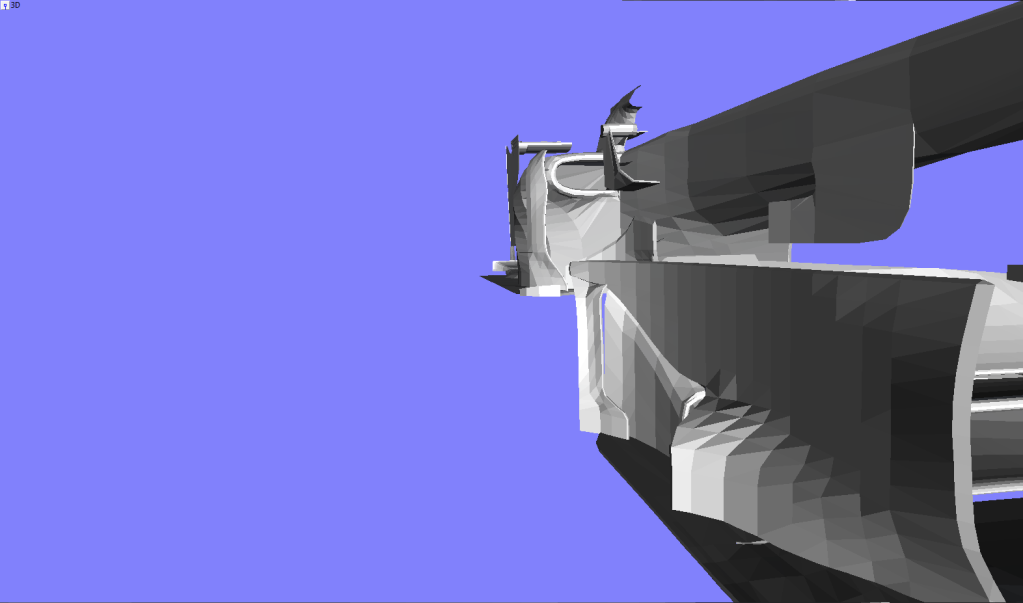
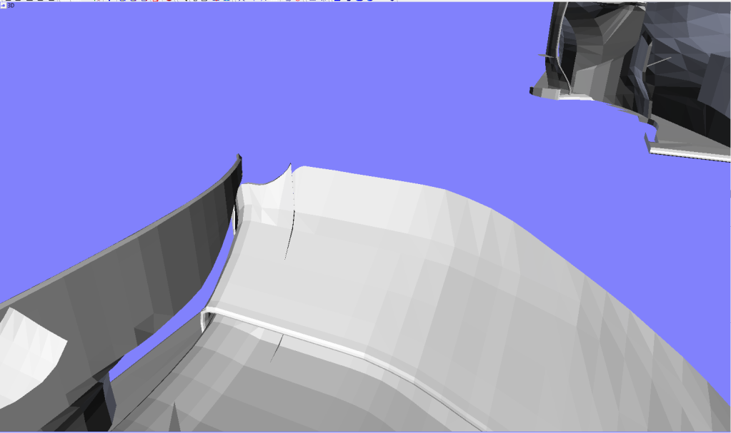
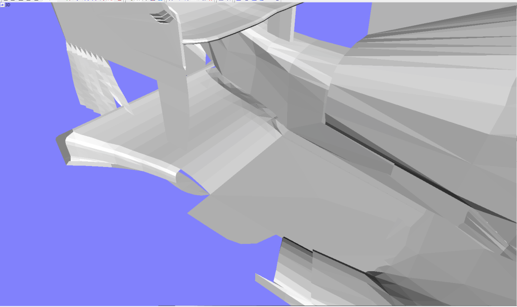
The front wing is brand new and no longer made up of 100 or so different section. The first plane blends into the foot plate creating a continuous surface, this allows for a slightly wider additional end plate and has better flow onto the second plane.

Image
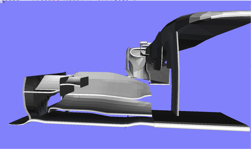
The inside edge of the third plane is bended upwards, here the wing is already really short chord length and has lower angle of attack. This creates a smaller vortex increasing wing efficiency.

Image
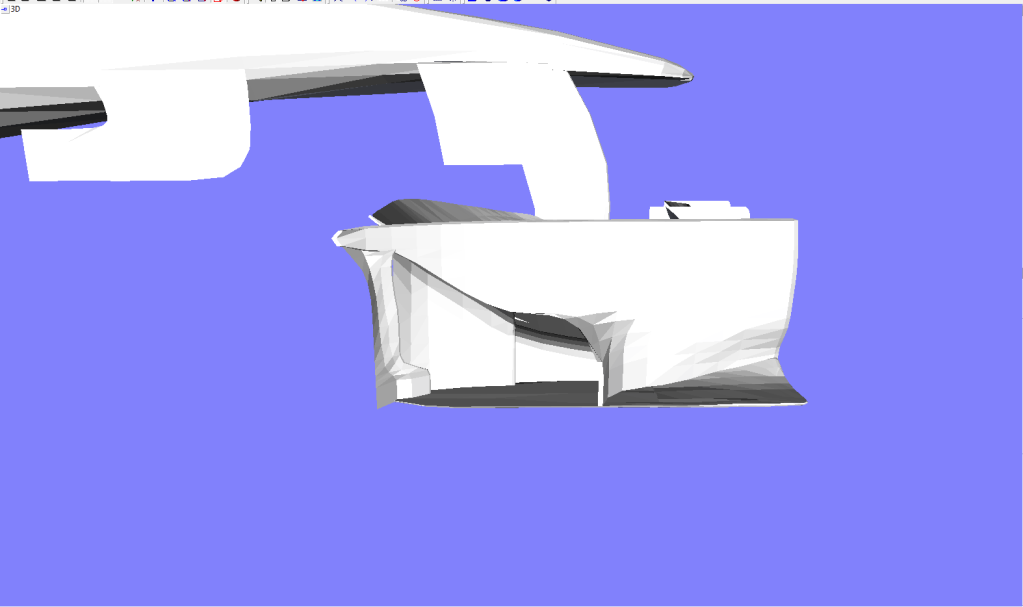
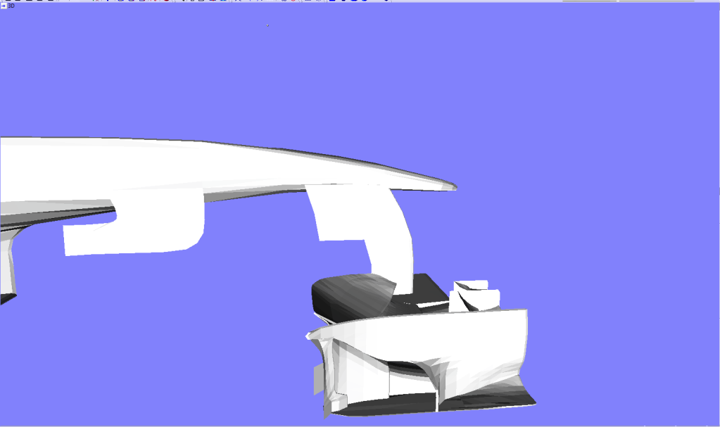
As for the end plate I went for a new solution, it shows great linage to Red Bull and williams solutions, but at the trailing edge of the end plate there is another section acting as a small slotted gurney/turning vane, aiding extraction from under the wing
Image
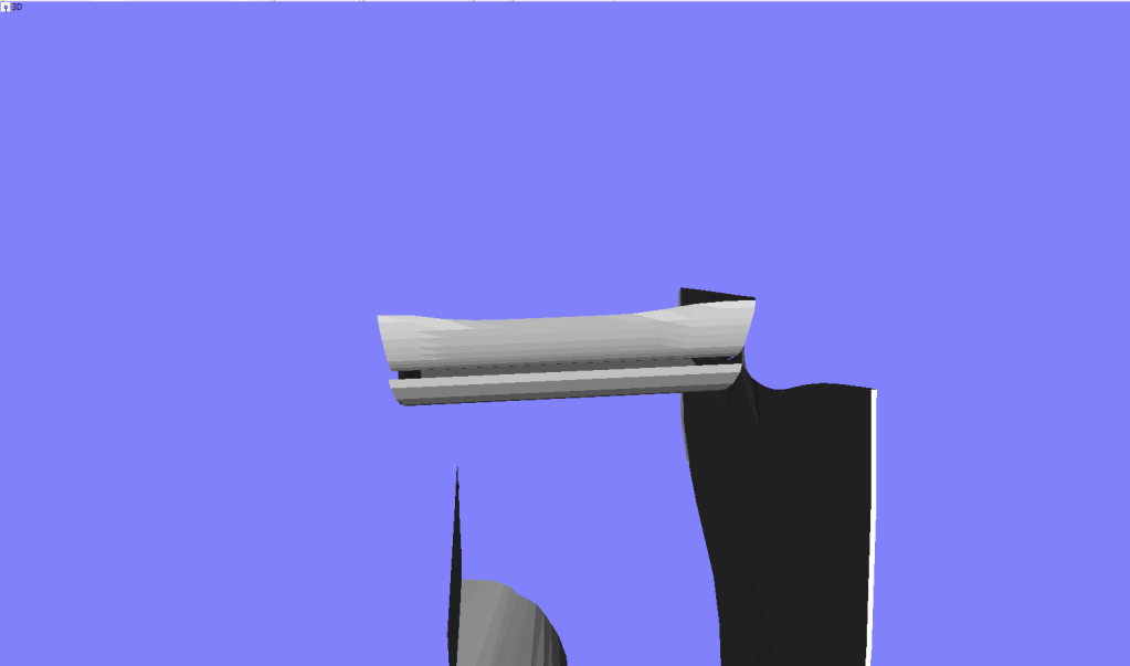
The part conencting to the footplate turns outside really quickly giving a huge area for air to head out of, aiding air around the front wheel.

Image
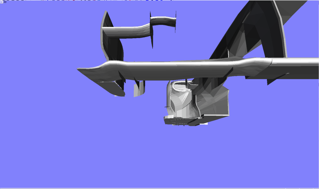
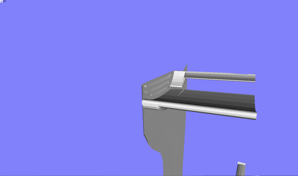
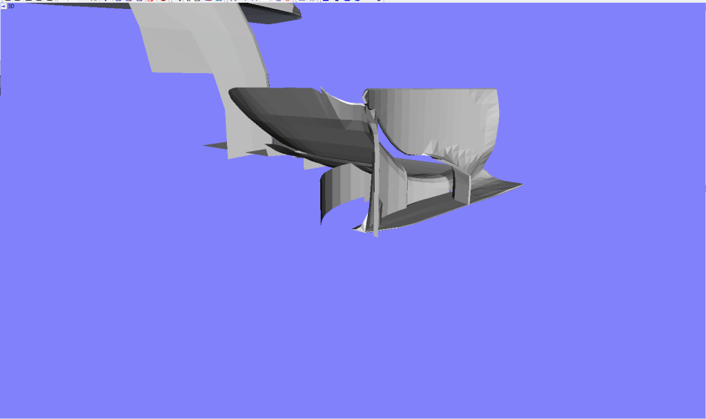
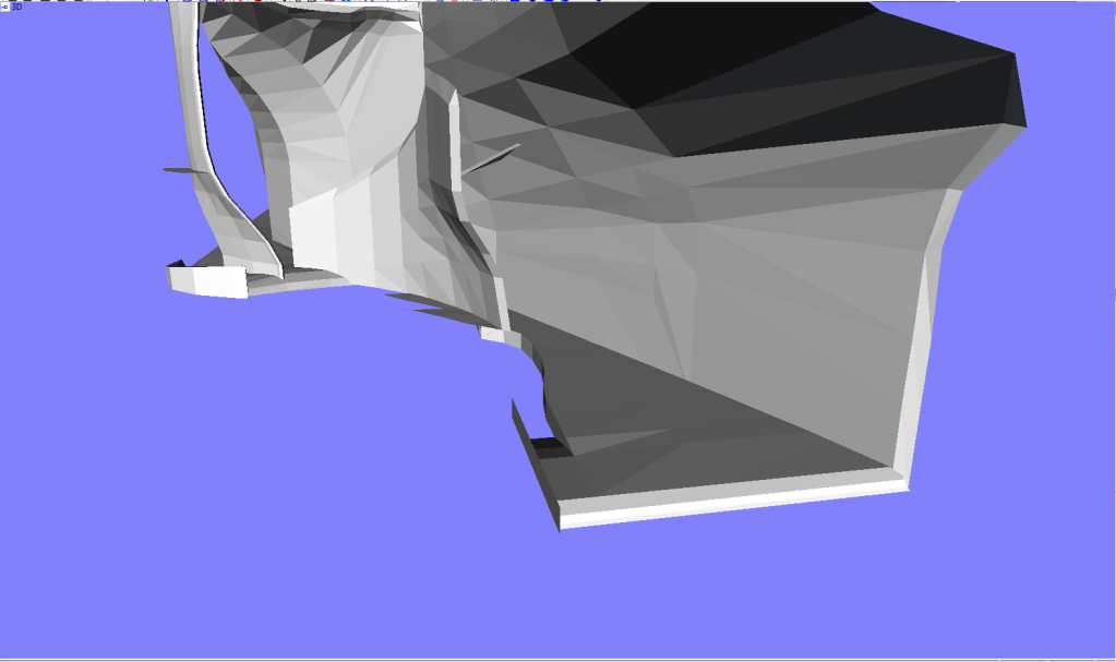
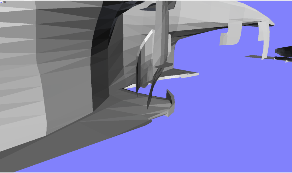
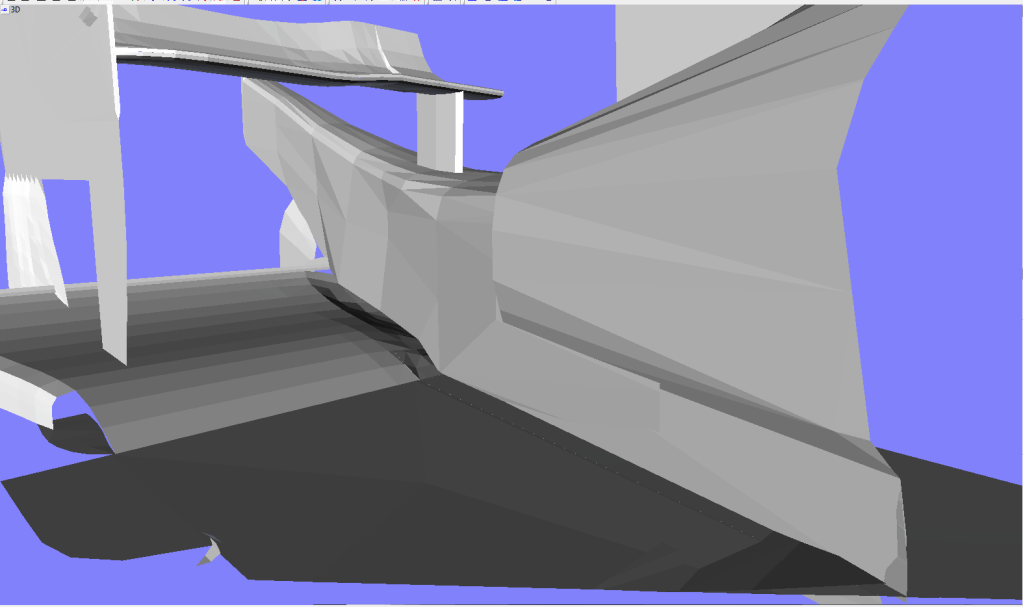
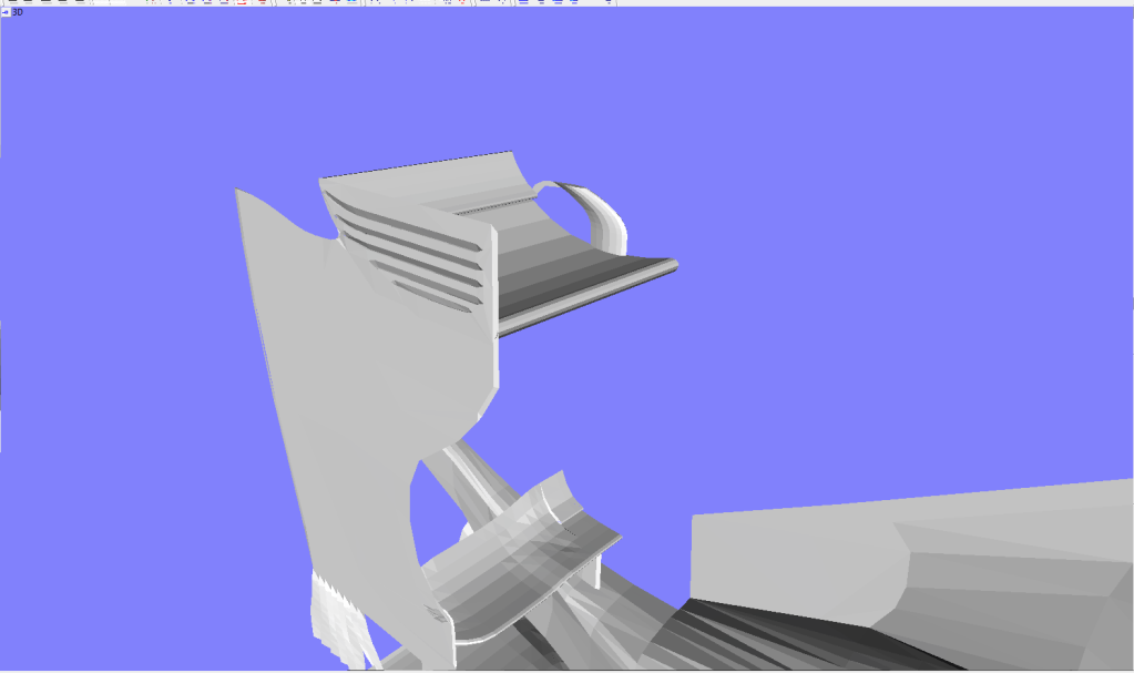
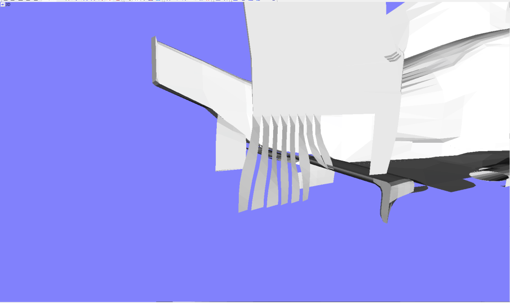
Under the wing are 3 strakes on the outside and 1 on the inside. These strakes aid downforce but also help air around the front wheel.

Image
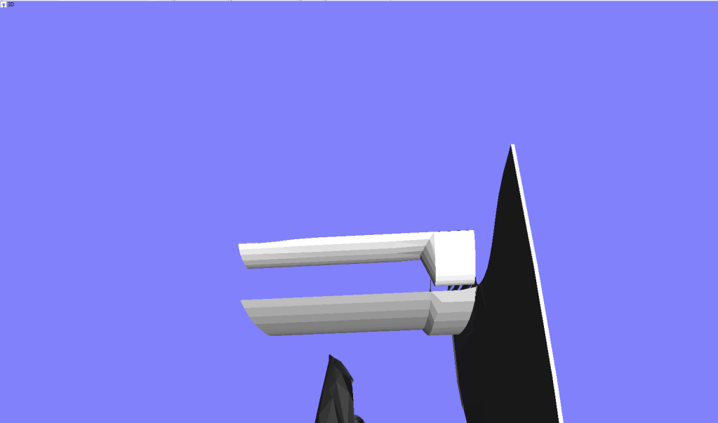
There is one thing that hasnt changed from the previous front wing, that is the outer edge. It still got a tab to guide air around the tire.

Image
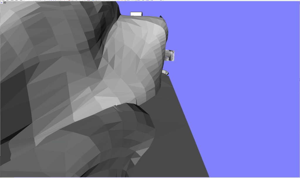
The pillar has changed too again, conencting to the back side of the central section again, together with that the pillar is longer to increase lower pressure under the nose, increasing downforce.
There also is a new barge board conencting to the nose, more alike the ones ran by Ferrari and Red Bull.

Image
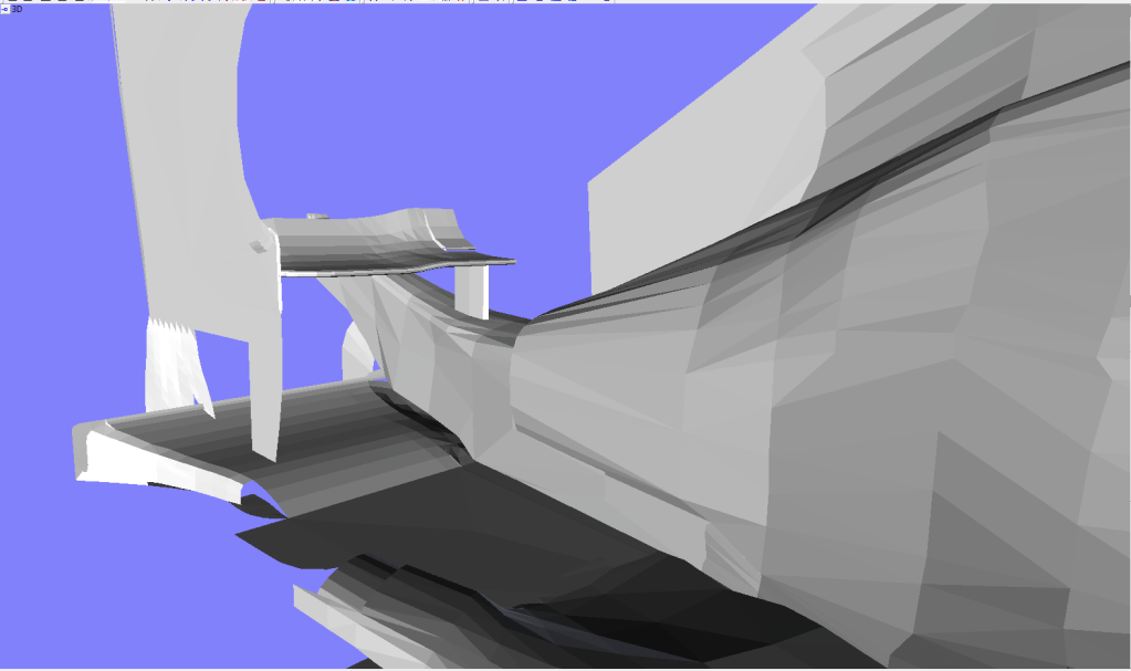
The splitter of the floor is new, it got a new solution where air from above the splitter blends with the air from under the car, here it together gets turned away from the step plane, just like regular solutions. This increases floor efficiency and reduces drag.

Image
Around the podvane the floor has changed too, the flip up on the edge of the floor was made shorter.

Image
The EBD was changed too, it now once again blows into the diffuser as well as outside of the diffuser wall.

Image
Image
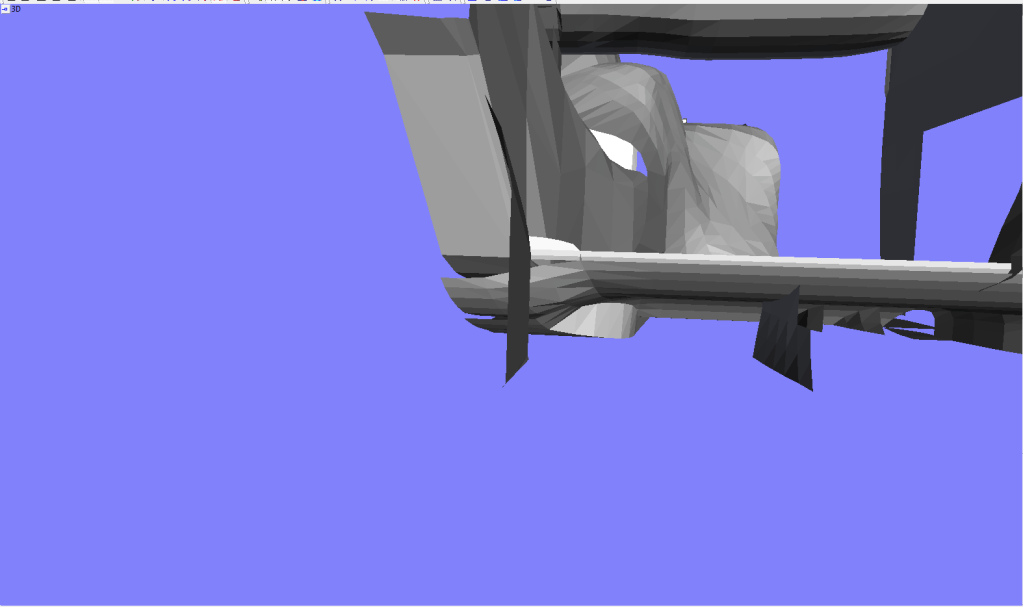
The diffuser now also got a slit in the central section, where air from the coke bottle go into a duct into the diffuser, this increases df.

Image
The strakes in the diffuser are changed too, there is one less and they now are more round shaped, increasing diffuser efficiency.

Image
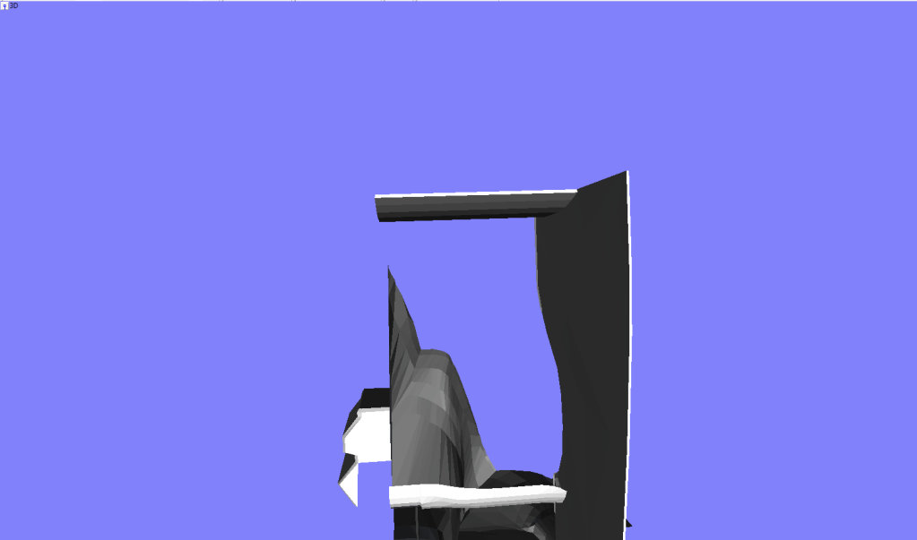
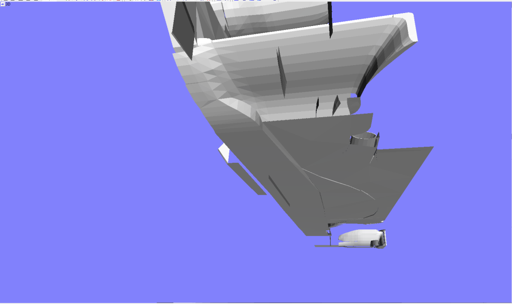
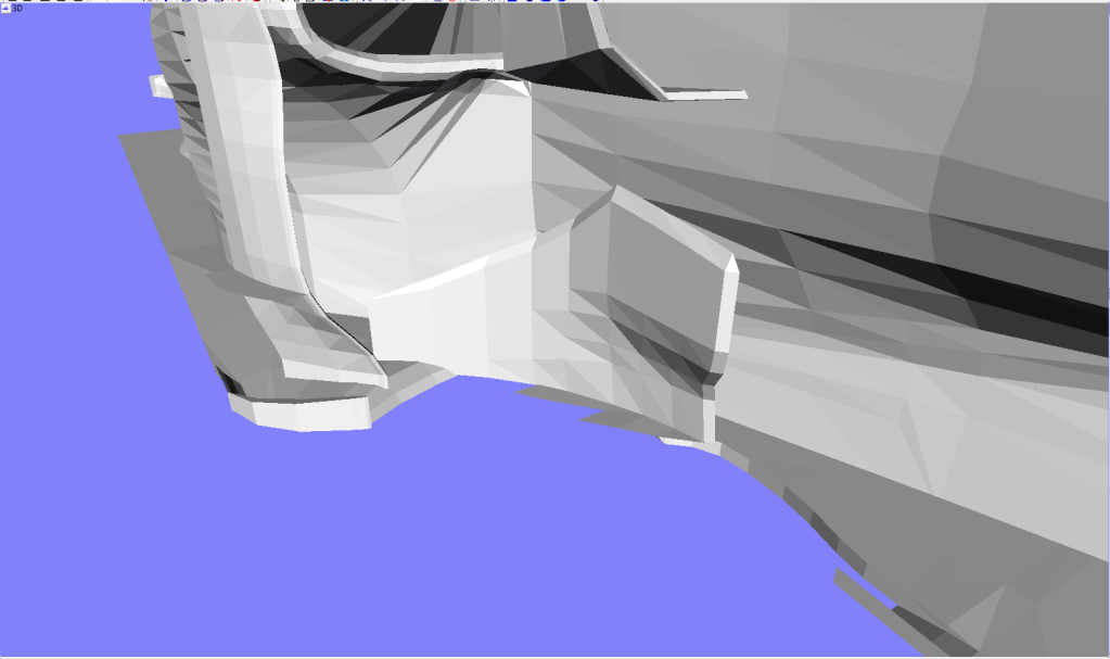
The sidepod changed too, towards the end it was made significantly smaller, increasing floor area and gets more air towards the beam wing.

Image
The whole rear bodywork changed, the cooling hole on the rear of the airbox was extended further back, it now is lower and blends around the gearbox, this makes the beam wing even eqasier to reach increasing downforce. The floor was made more efficient too because a cooling hole lower down was closed off.

Image
The bargeboard changed too, it now blends upwards on the first part, this creates a larger but less strong vortex. The edges on the reference plane where made larger too.

Image
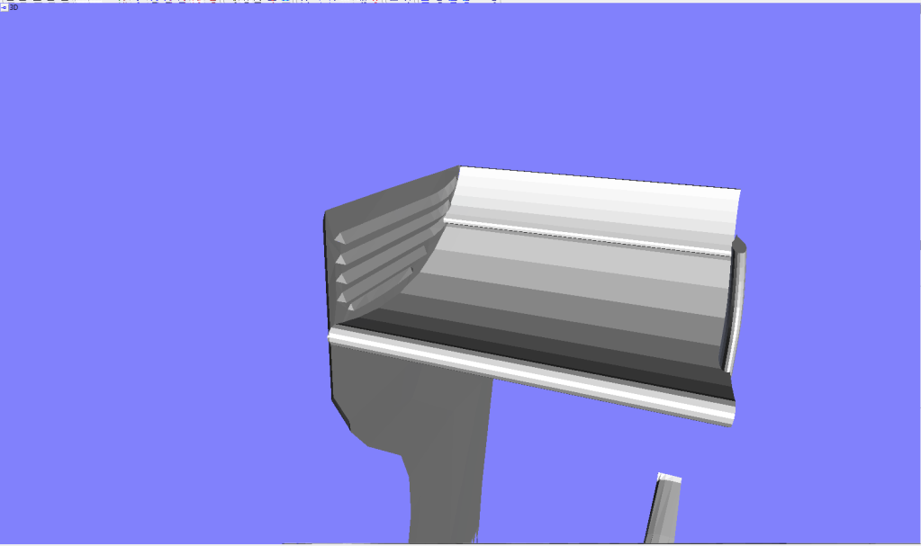
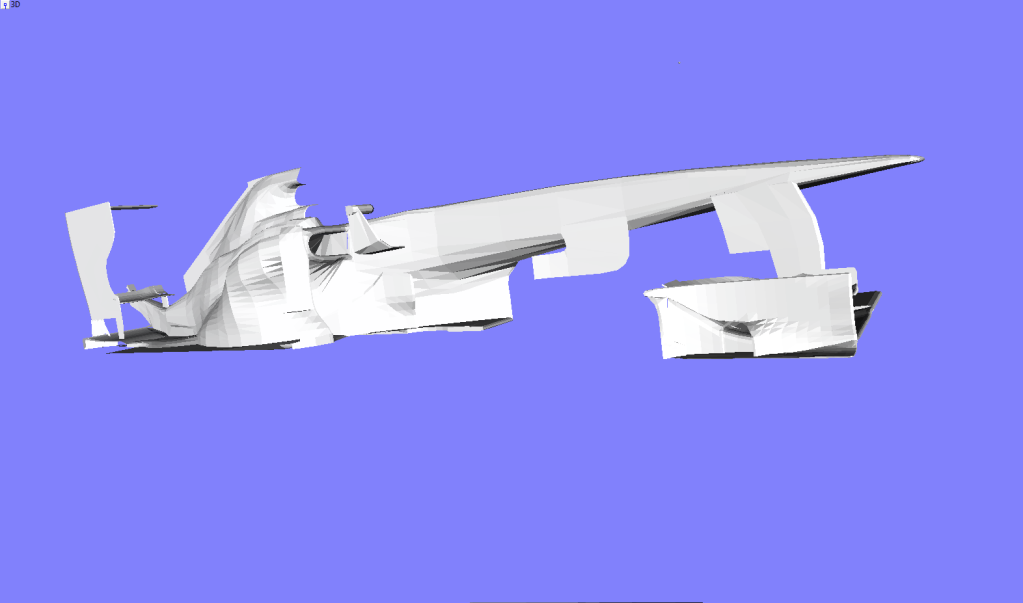
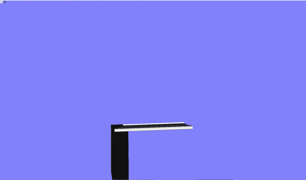
The rear wing is all new, kind of similair to the rear wing of the McLaren. Got a shorter flap to increase DRS efficiency and lower drag. The slits in the end plate are changed too, now they are horizontal creating a more natural flow.
Image

Image
The extension also is changed, consisitig of more pieces and it got 2 connecting to the floor itself. This reduces drag a bit better by sending air into the wake of the rear wheels
"Bite my shiny metal ass" - Bender

User avatar
Tozza Mazza
1
Joined: 13 Jan 2011, 12:00
Location: UK

Re: Wesley123's F1 Model

Post

Hi Wesley, very nice update, your car is always very nice to look at.

I know, having done this myself that it is very enjoyable, but don't you want more from it?

You quite clearly are very talented, so why not make a much more detailed (and less polygony) model, and have CFD run on it to improve your concept, and test your ideas.

wesley123
wesley123
204
Joined: 23 Feb 2008, 17:55

Re: Wesley123's F1 Model

Post

I sure would like to do so, only the problem is the conversion from the file format to a one that a CFD programma(which I do not know of itself) can read.

Although I would love to see it, I think there are a few problems in doing so in its own idea, to get a good impression you need serious computing power, that in turn is for most of us already a problem, then you need correct meshing etc. Gonna be a pain in the a$$ to do so, and with this program, where the model is proably going to be ruined while converting maks things even worse. Unless you can prove me that I'm wrong I think I'll stick with the powerfull CFD that runs inside my brains :P
"Bite my shiny metal ass" - Bender

User avatar
Tozza Mazza
1
Joined: 13 Jan 2011, 12:00
Location: UK

Re: Wesley123's F1 Model

Post

wesley123 wrote:I sure would like to do so, only the problem is the conversion from the file format to a one that a CFD programma(which I do not know of itself) can read.

Although I would love to see it, I think there are a few problems in doing so in its own idea, to get a good impression you need serious computing power, that in turn is for most of us already a problem, then you need correct meshing etc. Gonna be a pain in the a$$ to do so, and with this program, where the model is proably going to be ruined while converting maks things even worse. Unless you can prove me that I'm wrong I think I'll stick with the powerfull CFD that runs inside my brains :P
Haha, it's definitely possible, in the next few weeks myself and JordanGP should prove it is perfectly possible :lol:

We've had one test part analysed already and hope to have the front of the car analysed soon, and we're modelling in sketchup, a program very similar to Zmodeler.

wesley123
wesley123
204
Joined: 23 Feb 2008, 17:55

Re: Wesley123's F1 Model

Post

@Tozza Mazza; My medel shows it can also be not possible to do so haha, got myself a copy of Solidworks, imported the sent model(only the fw end plate) myself and it came out pretty weird.

Anyway, Italy update here, Lower df front wings and rear wings. I decided to make 3 rear wings, one higher df, one extremely low df and one really weird looking one.
Image

First up the low downforce rear wing:
Image
Image
Image
Image
This wing is a single plane wing with extremely low AoA to reduce df as much as possible, probably has too less downforce so there is an large gurney tab on the edge and an small addition on the crahsbox to add a bit of downforce.

And the high downforce wing:
Image
Image
This is probably the most efficient wing, it is cut in chord and frontal area as well as angle of attack, plus it makes use of the DRS to reduce drag.

The special rear wing:
Image
Image
This wing is interesting, on the outer edges it is a regular high aoA wing, but over the rest of th wing it is really short chord. The wing makes use of DRS so the low aoA part of the wing will get a nose up angle, generating lift. The way the short chord and long chord parts are conencted will drive air in behind the the high camber piece, this reduces drag and creates an overall smaller vortex.

Front Wing:
Image
Image
Image

The front wing is reduced a bit in profile, the inner tip is shorter in chord and there are small edges cut out to reduce overal area.
The inside wing element of the cascade is gone as well as less area of the outer cascade. The end plate stops well before the footplate edge, reducing overall drag.
The nose also is higher, longer and more pointier, reducing drag and increasing floor efficiency as well as making the pillars more efficient.
"Bite my shiny metal ass" - Bender

User avatar
MIKEY_!
7
Joined: 10 Jul 2011, 03:07

Re: Wesley123's F1 Model

Post

Nice update. Not sure about the so called weird RW though. I would have thought it was better to have higher AoA in the centre and then lower towards the endplates to reduce the vortex formed in the cutout. Also would have thought the massive slot gap would reduce your efficiency. PS bad luck with the CG programs, they can be nasty ](*,)

wesley123
wesley123
204
Joined: 23 Feb 2008, 17:55

Re: Wesley123's F1 Model

Post

thanks.

Doesnt necesary matter if it is done in the center or on the outsides. My take on it was that it would work in the most optimal flow field there. It is the easiest way to implement DRS on too.
On the outer wing tips this setup will generate a bigger vortex than with low AoA, but i tried to manage that by sending air from through the huge 'slot gap' behind this part, reducing the effect of the vortex.

Main plate has a different profile on the outer tip too to match the shape of the Flap.

This wing isnt that well deveopped though, and certainly needs CFD to run though, although I am sure an multi element wing like this(different sections on the horizontal axle) surely has potential
"Bite my shiny metal ass" - Bender

User avatar
MIKEY_!
7
Joined: 10 Jul 2011, 03:07

Re: Wesley123's F1 Model

Post

I rekon you may be on to something. The airbox will of course get in the way of any complex stuff in the middle so well done thinking outside the box. Nose up DRS could cause problems since i don't think it is allowed to be above the usual max height even when open.

wesley123
wesley123
204
Joined: 23 Feb 2008, 17:55

Re: Wesley123's F1 Model

Post

I dont know, I believe the Ferrari DRS had a little nose up angle.
"Bite my shiny metal ass" - Bender

User avatar
MIKEY_!
7
Joined: 10 Jul 2011, 03:07

Re: Wesley123's F1 Model

Post

Now why would they do that?

User avatar
scuderiafan
11
Joined: 06 Nov 2010, 15:14
Location: United States

Re: Wesley123's F1 Model

Post

MIKEY_! wrote:Now why would they do that?
If I understand right, and the "nose up angle" refers to the angle of attack, a nose up angle would produce slight lift on the wing. This would result in less drag, and a better aerodynamic efficiency for straight-line speed.
"You're so angry that you throw your gloves down, and the worst part is; you have to pick them up again." - Steve Matchett

Patiently waiting...

User avatar
MIKEY_!
7
Joined: 10 Jul 2011, 03:07

Re: Wesley123's F1 Model

Post

Anyone got a pic?

wesley123
wesley123
204
Joined: 23 Feb 2008, 17:55

Re: Wesley123's F1 Model

Post

Image
Here, as you can see from the back the santander logo is visible which suggests a slight nose up angle. Just because it produces lift instead of downforce doesnt mean it also produces less drag. This configuration probably produces the same amount of drag as an wing with a similair amount of positive angle of attack, that is when you dont take the main plane into consideration. Creating an nose up angle in this case would possibly mean that the downforce the main plane creates is neglected, causing a bit less drag.
"Bite my shiny metal ass" - Bender

User avatar
MIKEY_!
7
Joined: 10 Jul 2011, 03:07

Re: Wesley123's F1 Model

Post

Somehow the nose up flap is interacting with the air flowing over the main plane and reducing drag. I don't think just the fact that the lift cancels the DF can reduce drag, in fact i'd say that produces more. My bet is that there is some kind of separation on the main plane as a result of the nose up flap. Would have to run CFD to be sure though. Or maybe it reduces up-wash from the wing, not sure how effective that would be.