In this thread I will be unlocking a few secrets hidden within this part - The F1 Crankshaft, mainly its construction, and some other features. For a good period of time a few things had always bothered me in terms of oil ways and so on.
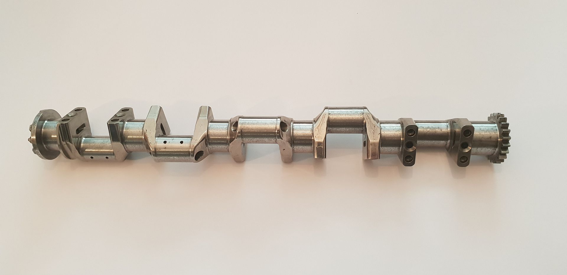
The part below is from the Cosworth TJ V10 Engine - please be advised this crank has been in poor storage for the past while with the result it is now a display item only and will not be ran again. Its counterweights have also been removed but they are pretty inanimate objects in a way. With that in mind and ignoring the surface finish lets delve in and see what it has to offer.
Just to give a quick overview - F1 Crankshafts are oiled from one end - the oil travels along the crank internally, oiling each journal as it goes. In this case it is just the conrod journals that get fed from the internal oil drillings. The main journals get oiled from the block drillings as would a normal road engine. The key aspect in terms of F1 Crankshafts is keeping the oil supply to the big end journals and at the same time keeping the crankshaft cool as a single unit. Remember the F1 V10 Crankshaft is pretty long, and outputs approx 915hp from one end - so it has to be kept well in check in terms of cooling and lubrication...
Onto the part itself - I'm starting first with a few basic overview shots, I'll touch on the finer details as we go,
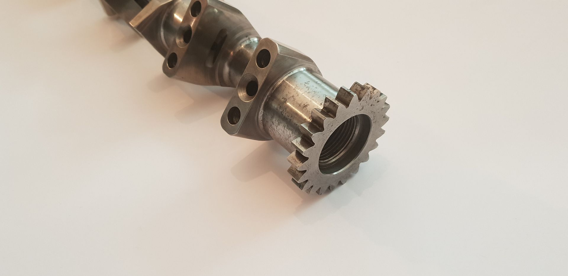
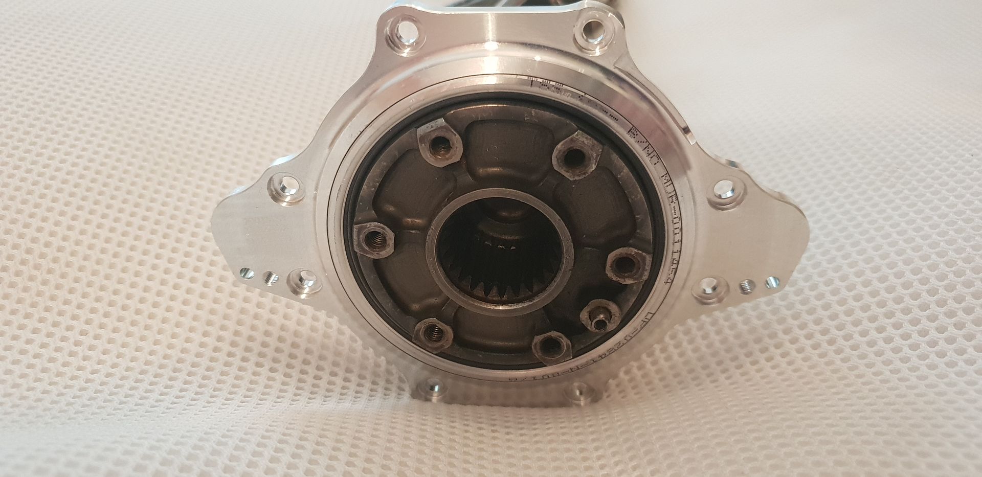
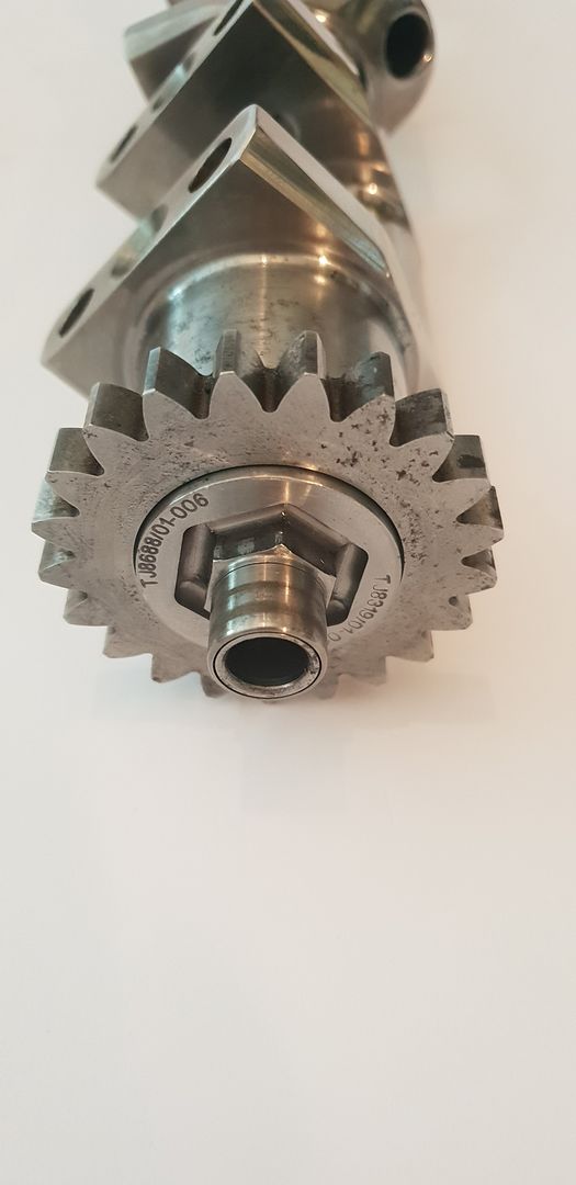
The output end,
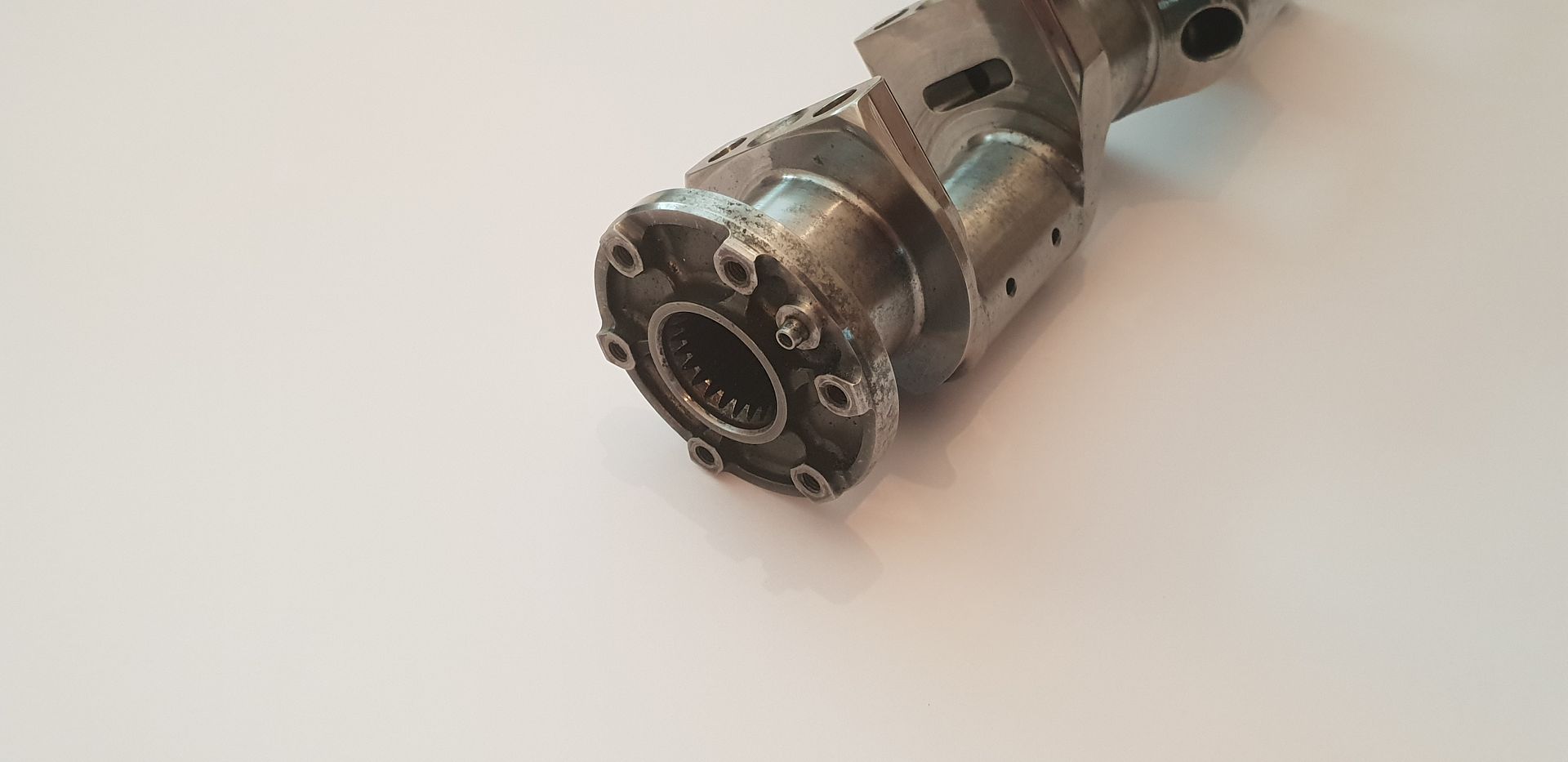
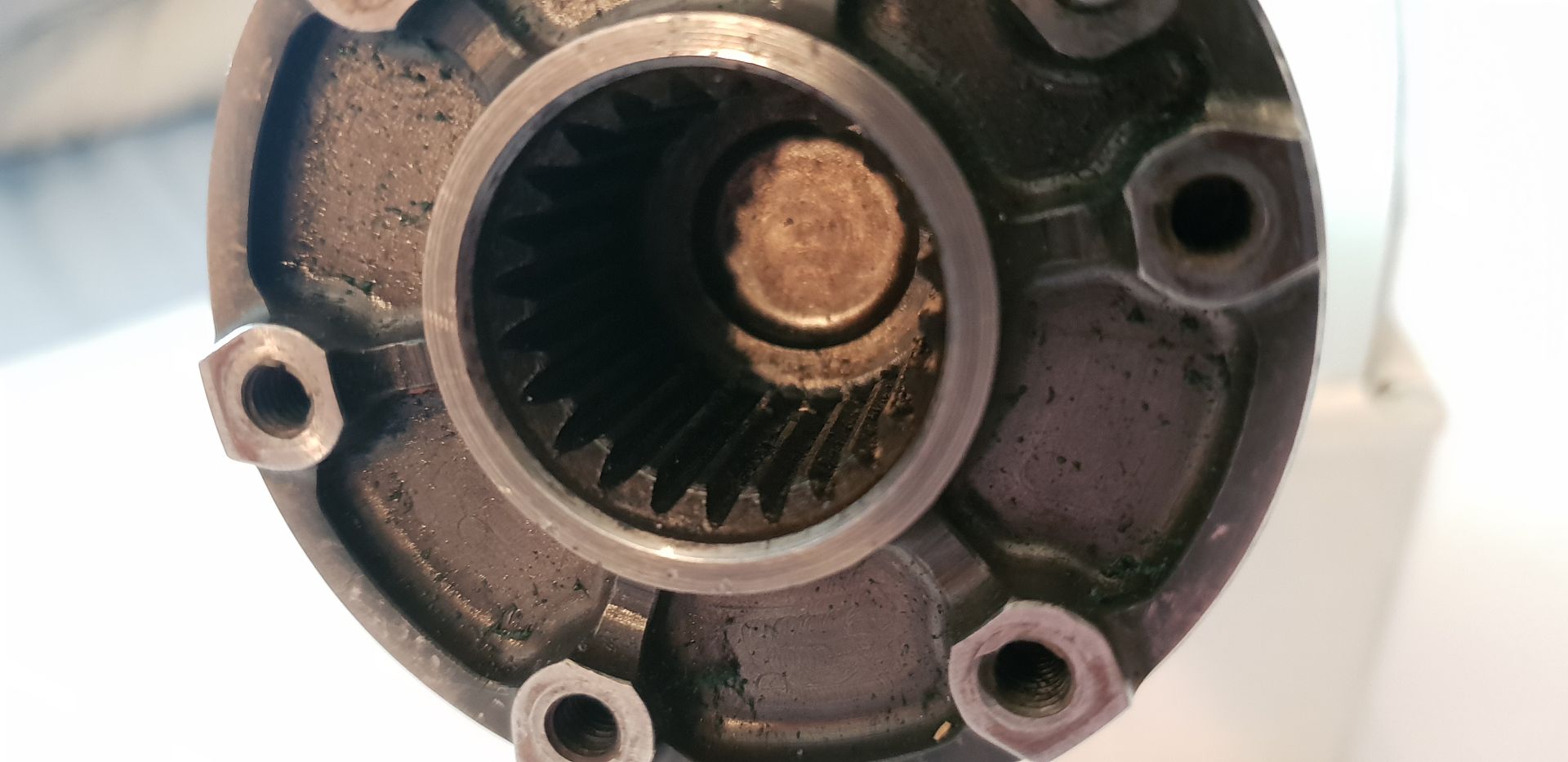
Into which the output gearbox shaft locates,
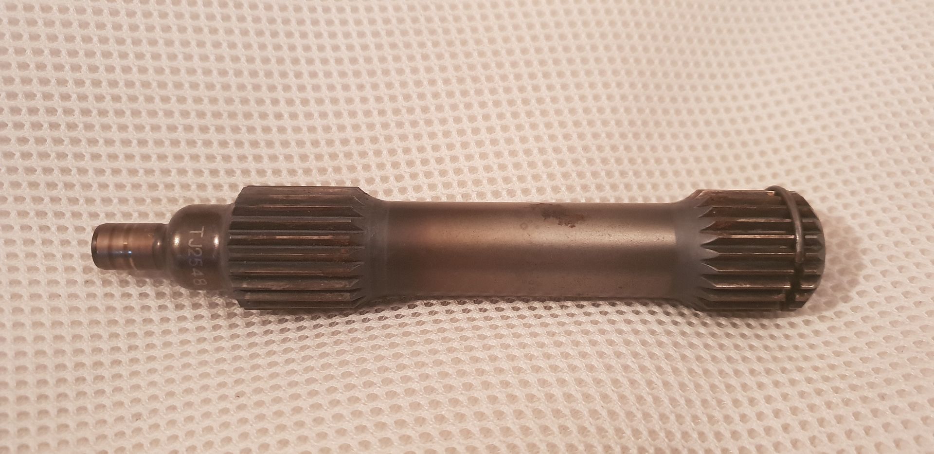
The end of the shaft locates into a pilot bearing in the gearbox and also of course transmits power to the clutch basket - which is hung off the gearbox bulkhead with twin angular contact bearings,
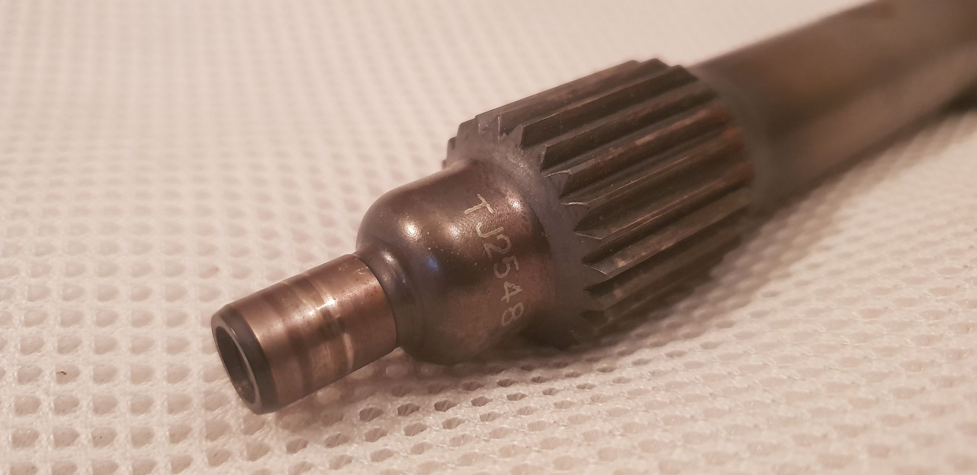
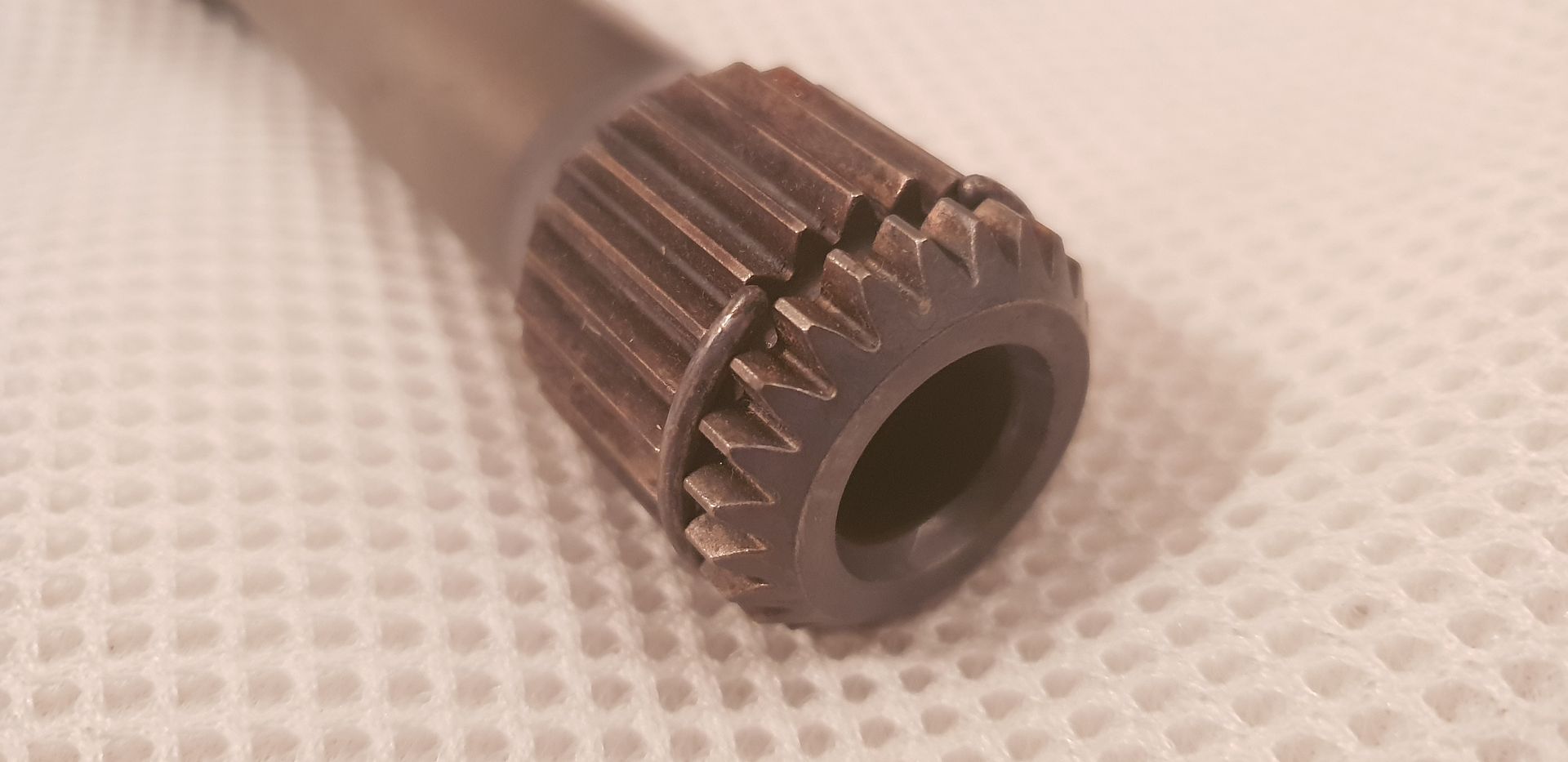
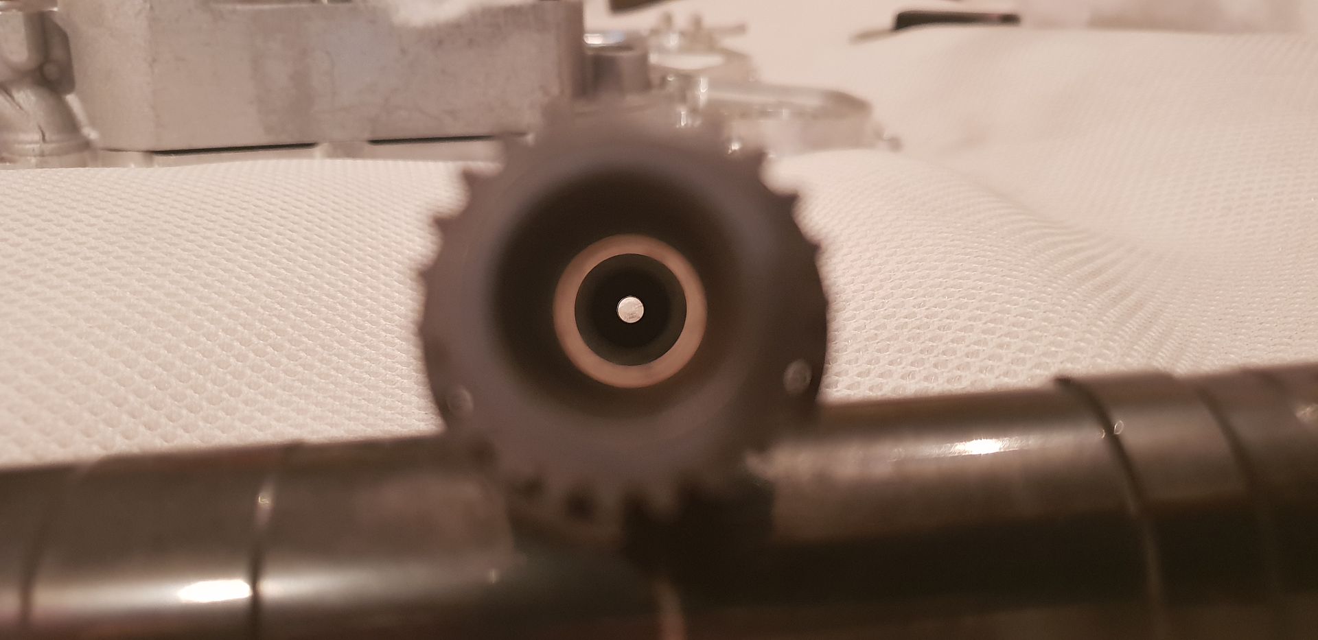
The shaft is hollow and allows some compliance in the line of torsional vibrations present in the crankshaft, the splines either end also allow for any misalignment,
The crank seal locates too on this end - the far end has no crank seal of course as it is open to the timing gears,
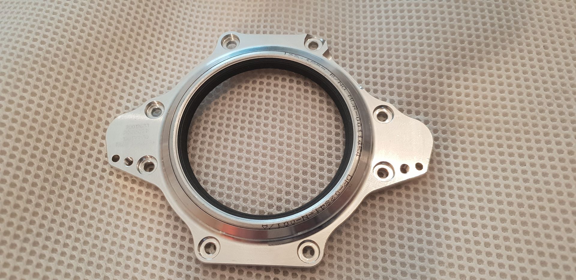
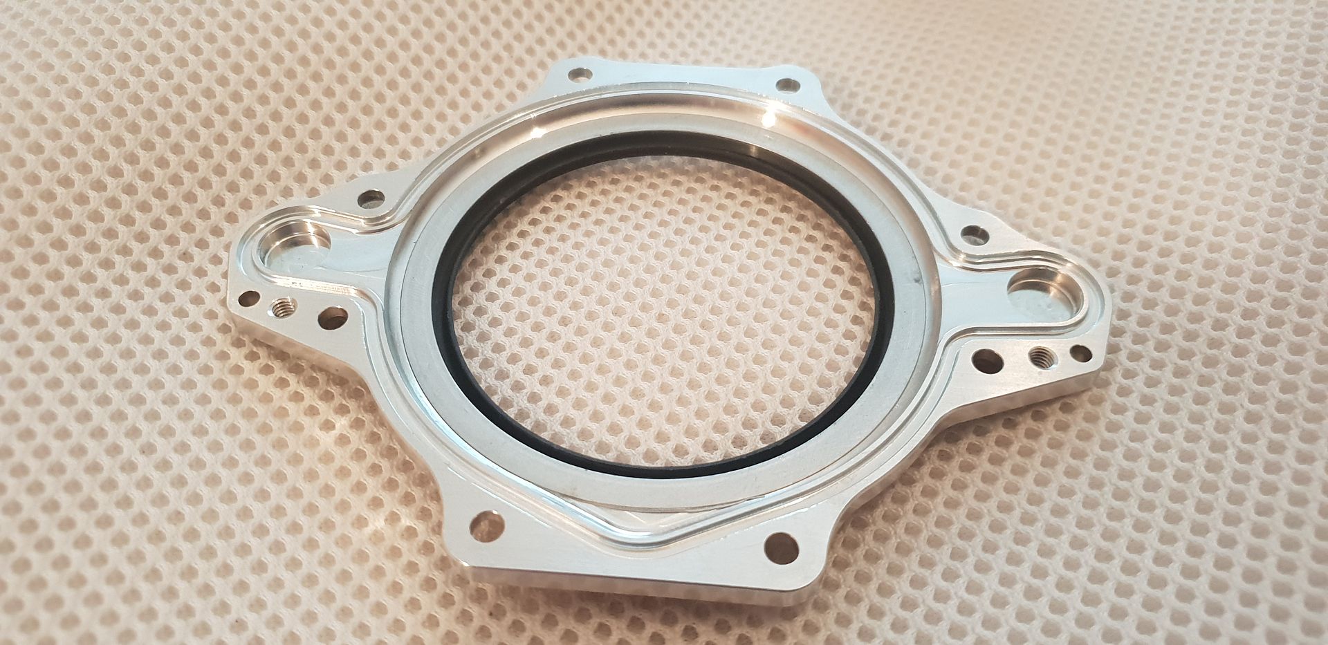
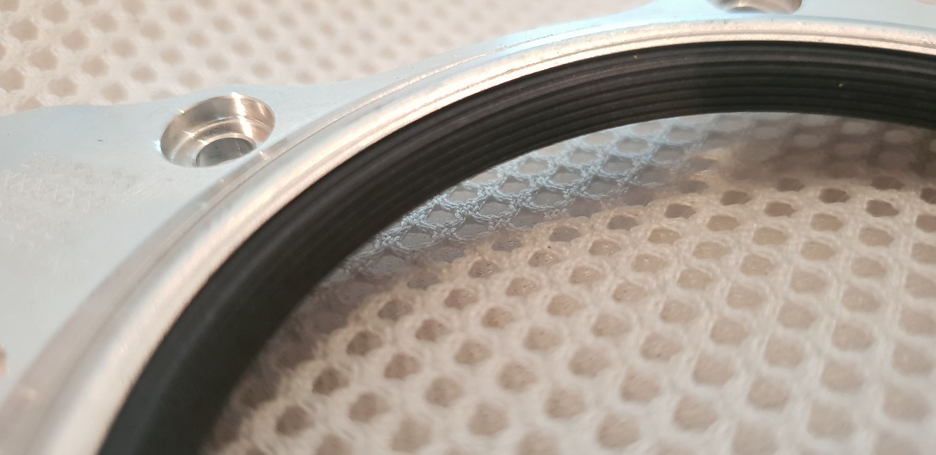
Its of the multi lip design and very stiff...keep in mind the crankcase is under vacuum,
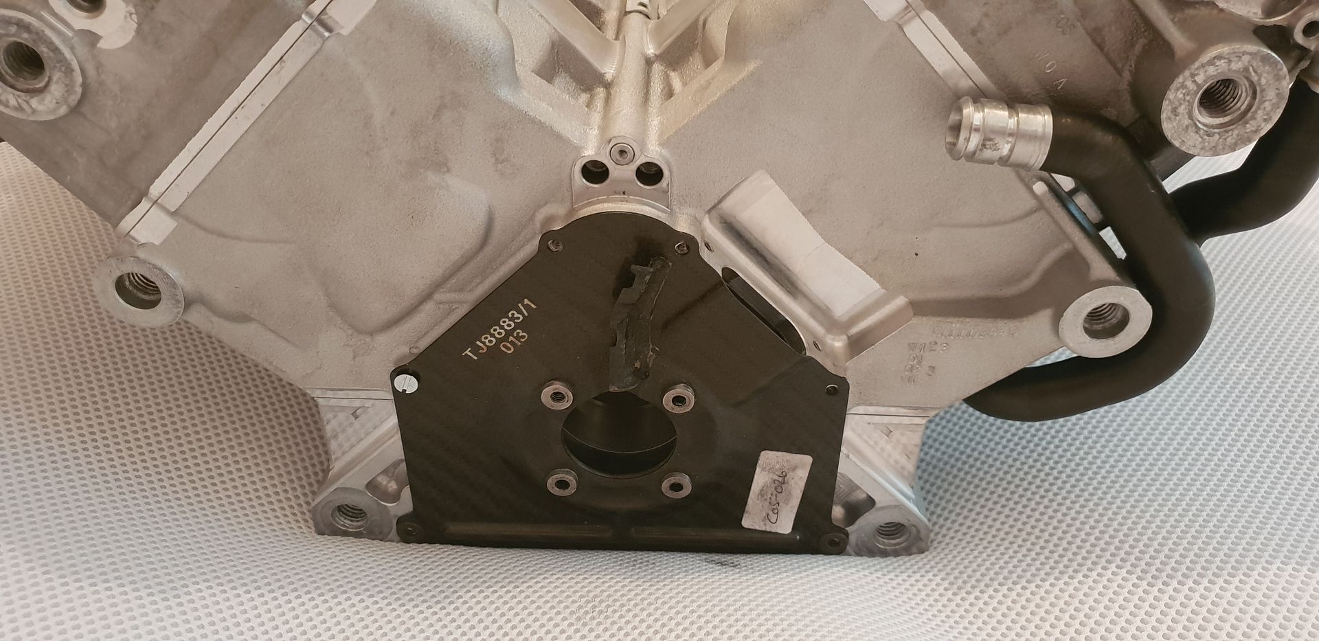
Where it mounts to block,
Fitted to crank,
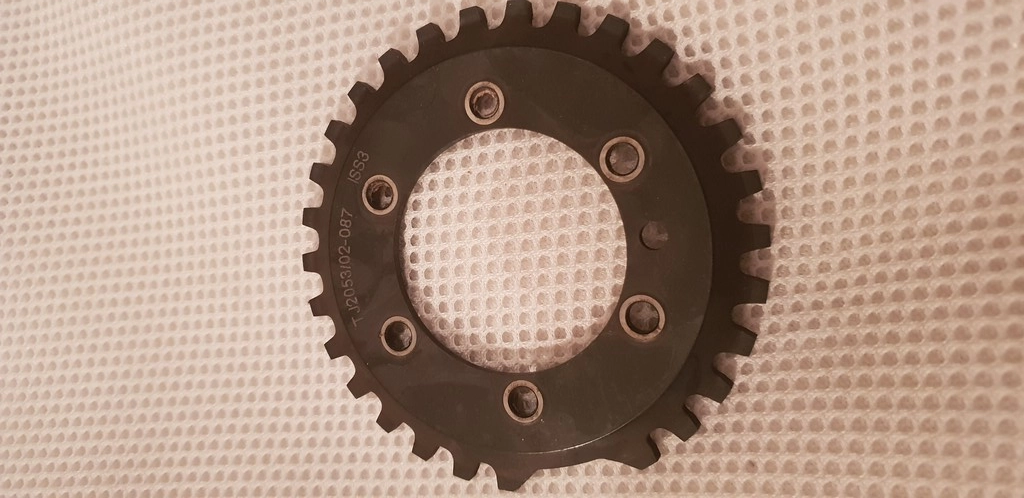
Onto this end also goes the toothed trigger ring for crank rpm monitoring,
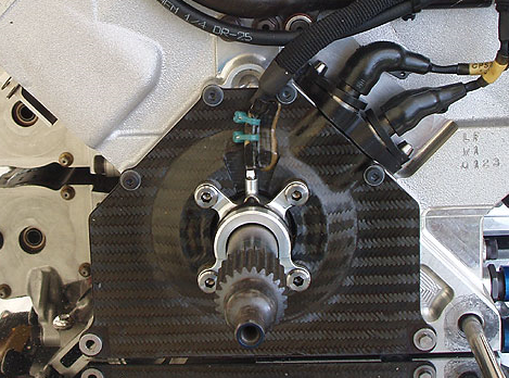
The lot gets covered when mounted with a CF cover,
Fully assembly below,
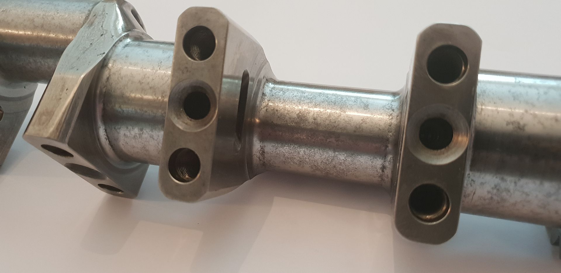
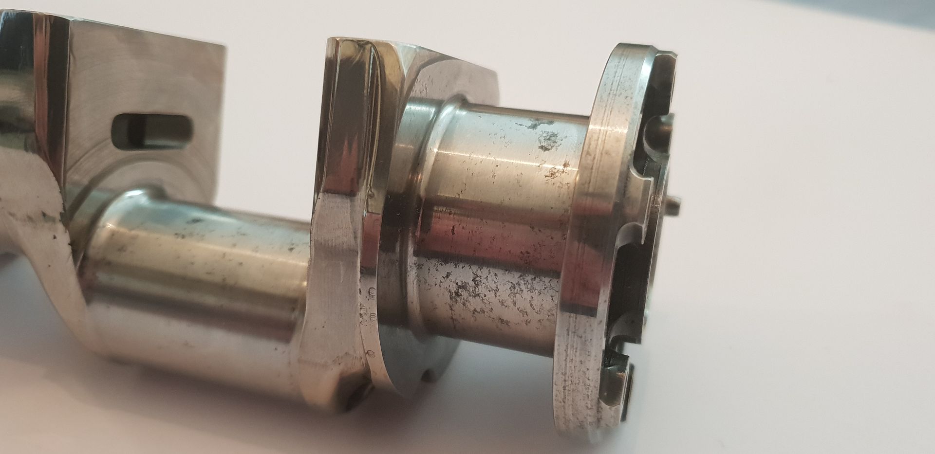
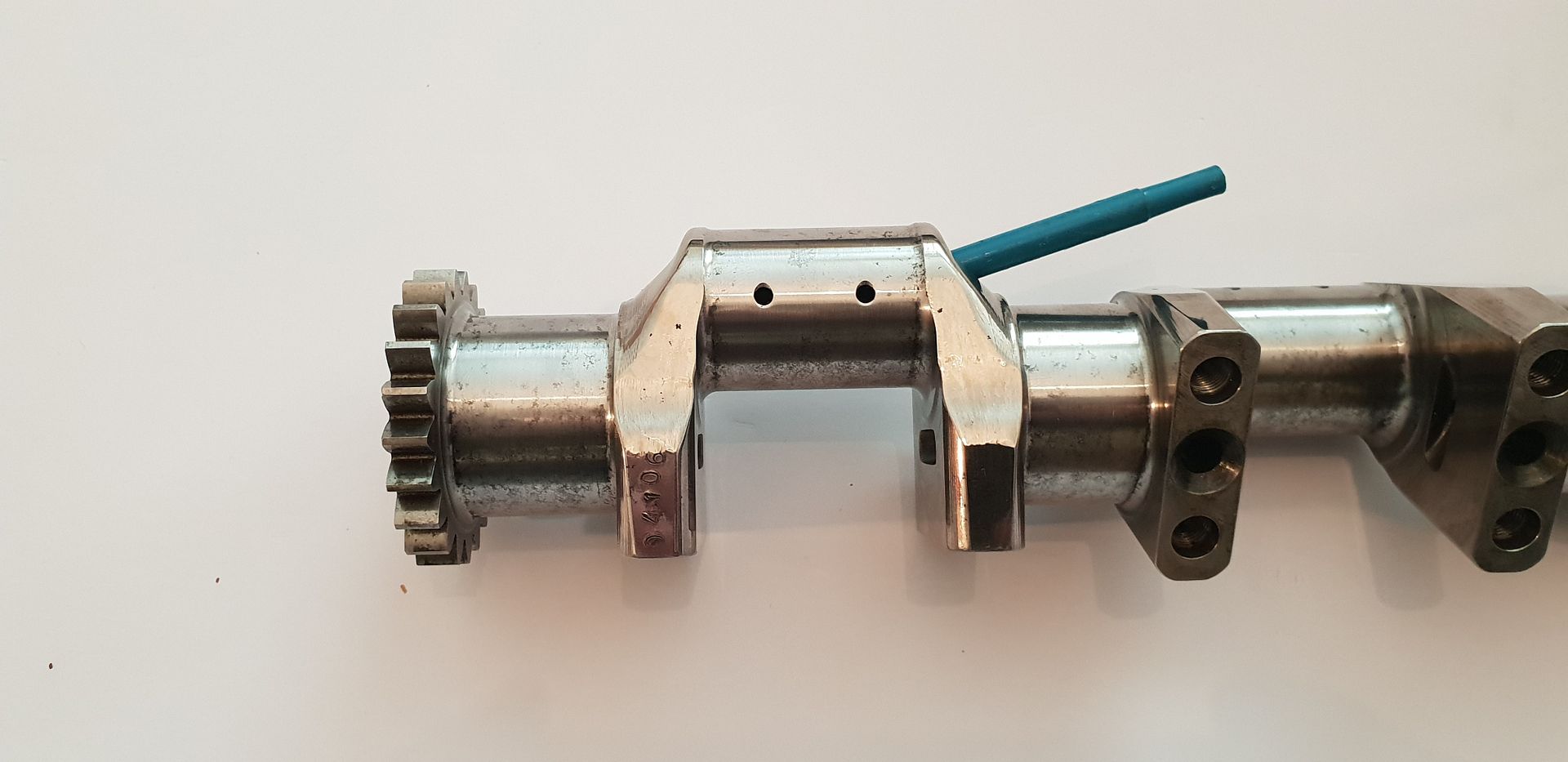
Moving up along the crank we can see the oil way drillings and journal fillet details,
The counter weights bolt on to the locations below accurate location provided by a steel pin,
The counterweight visible below bottom left,
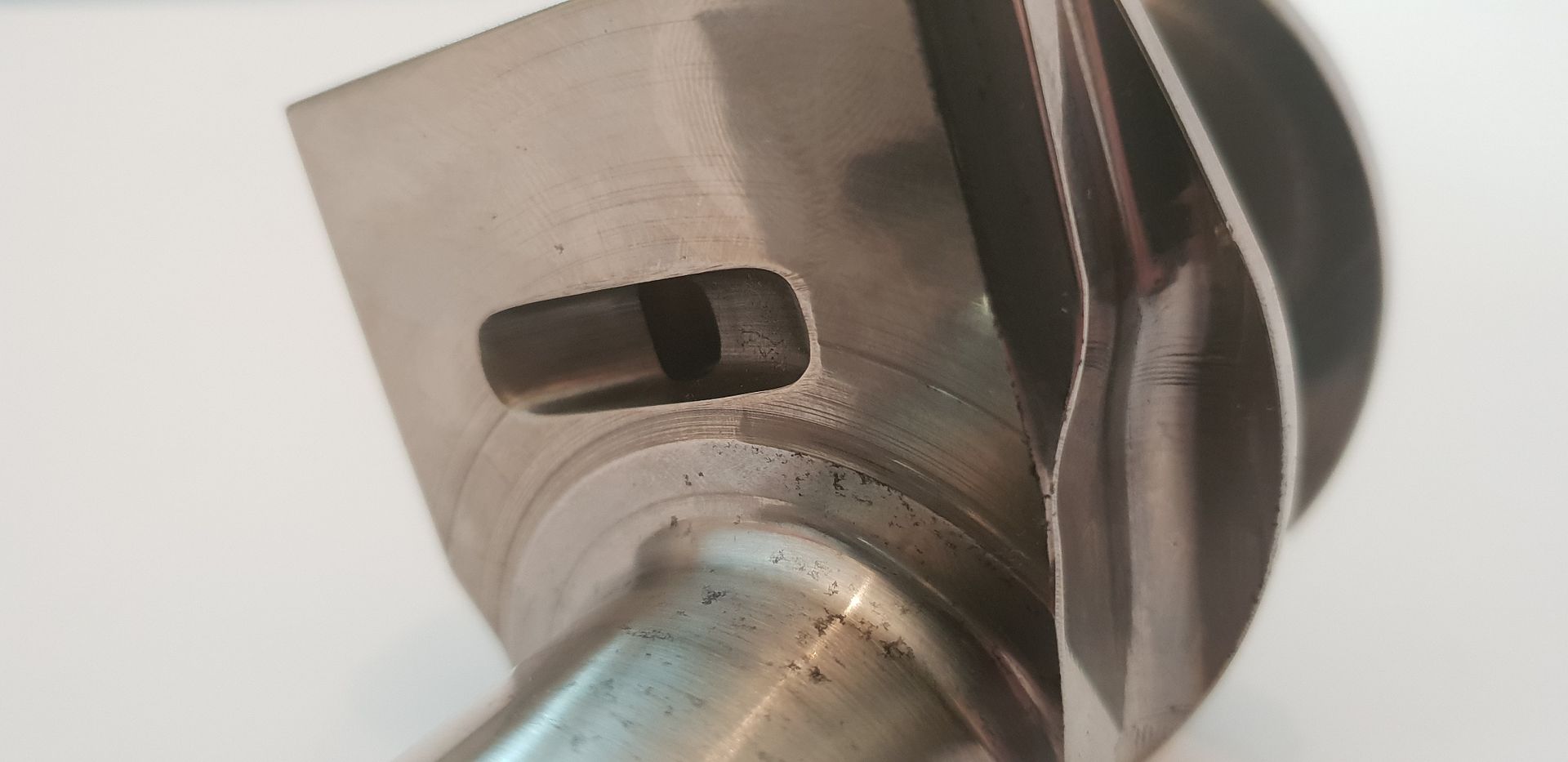
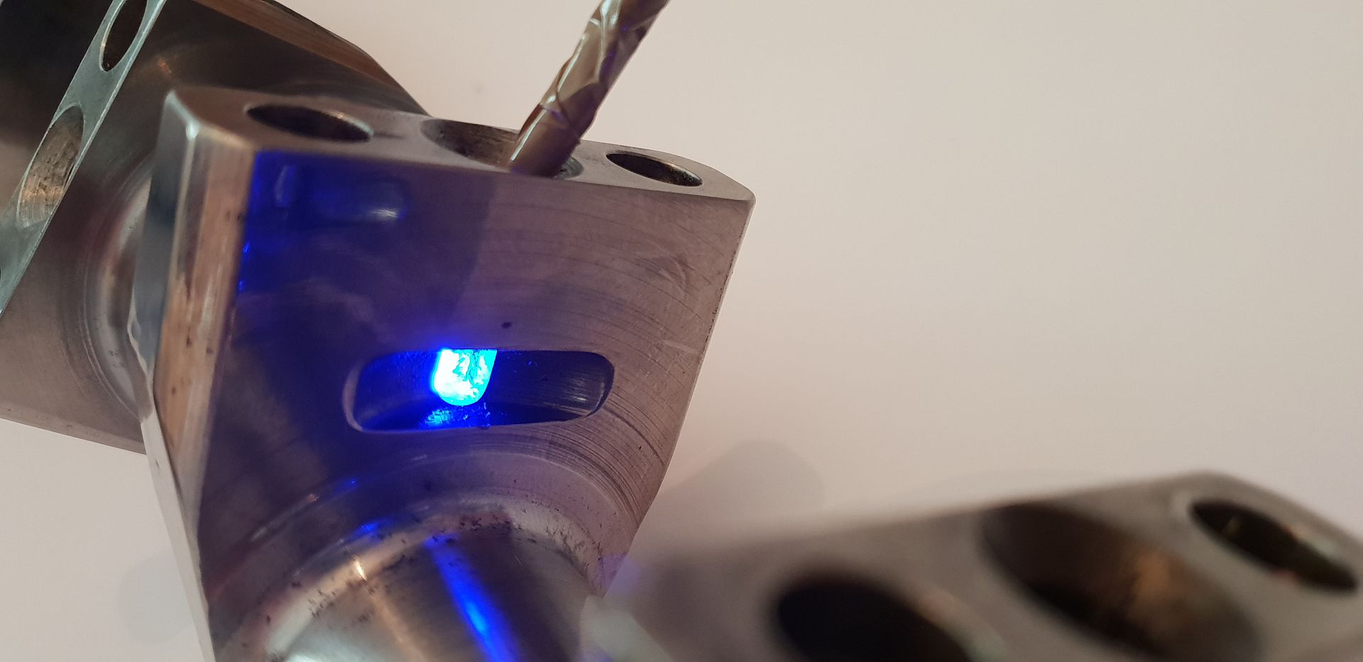
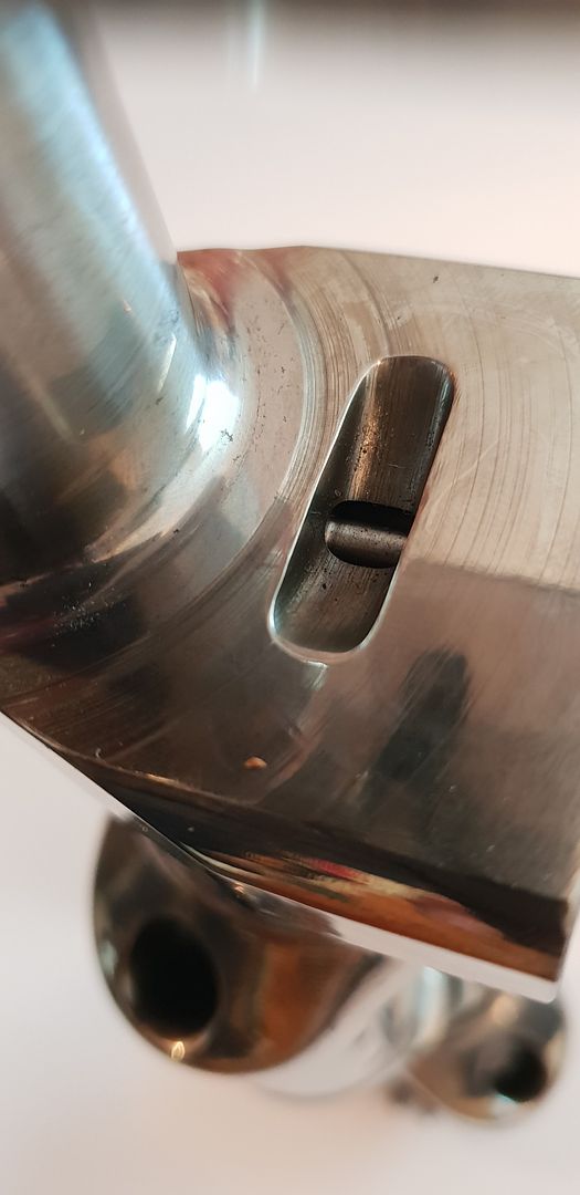
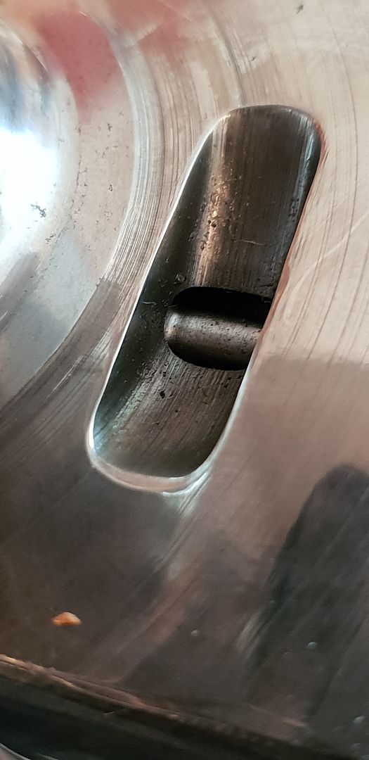
Again, notice the journal fillets...they are 4mm radius on big ends, and 2mm radius on main journals. This fillet detail is one of the most critical items on a high performance crank. Notice too the machined pocket - this is nothing more than a groove scooped out to meet a vertical drilling in the main crank mass - a waisted plug is inserted into this vertical drilling which in turn allows oil to circulate some what into the main mass in order to cool it - more on that later in thread,
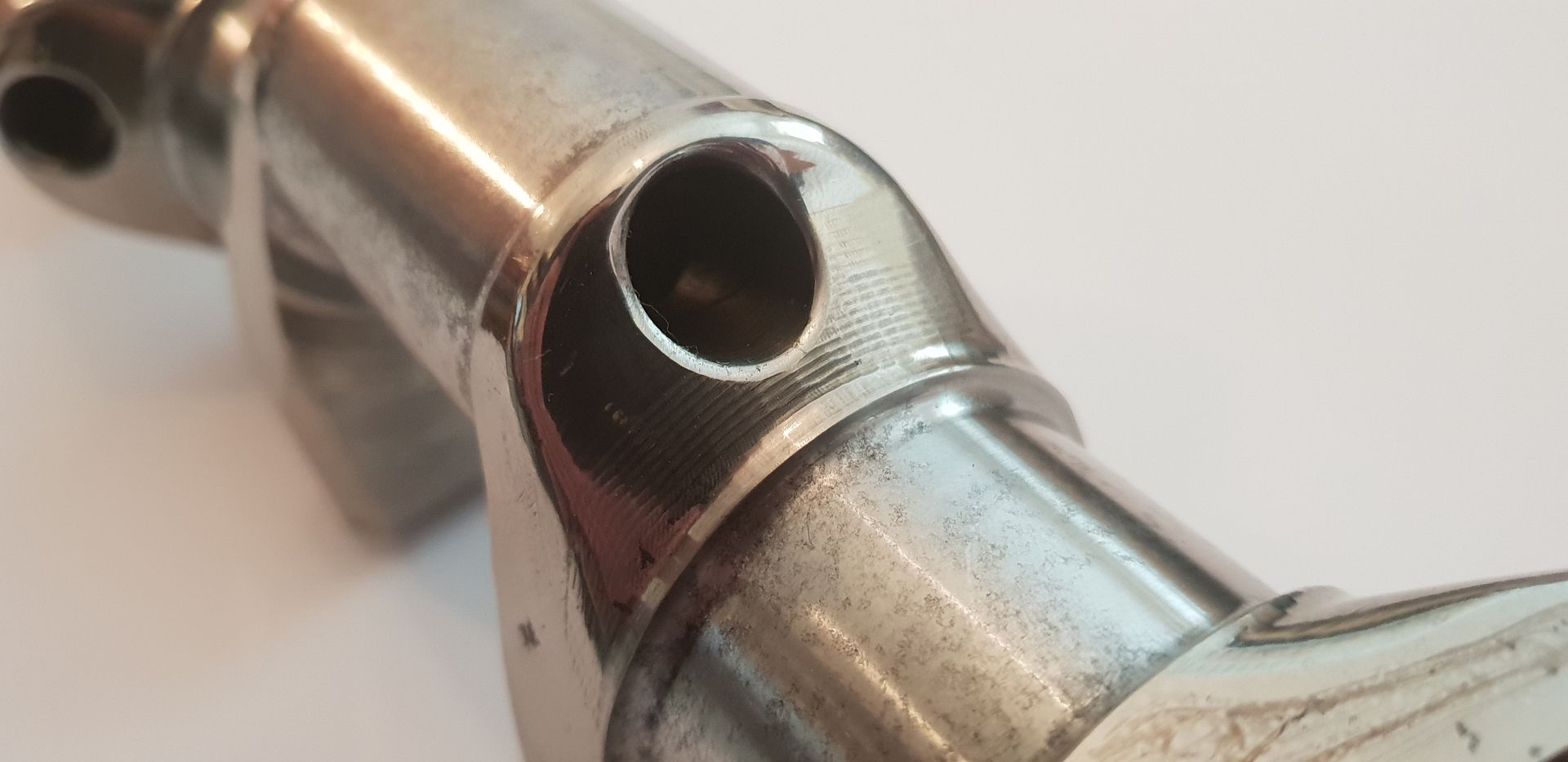
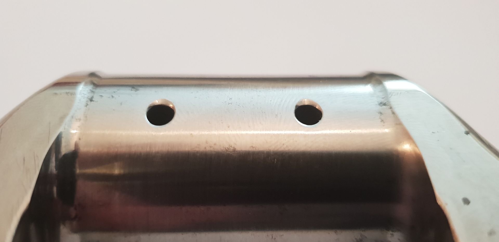
The big end drillings - each journal shares two rods - these holes enter into the internal oilway and are 3.5mm in diameter. They also have an eased trailing edge to promote oil wedge formation at low rpm in respect to the hydrodynamic oil film present between journal and shell pairs,
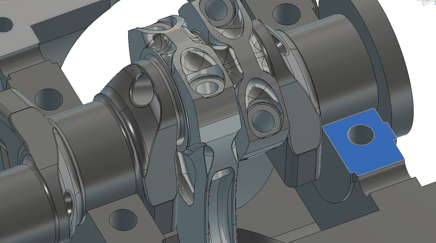
In the cad view below the crank rotates clockwise - clockwise when viewed from the timing gear end, therefore it is important to note that the big end journal drillings are located forward of top dead center and in the least area of downward force exerted by the conrod during the power stroke,
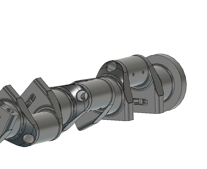
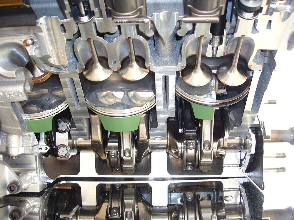
It is also worth noting that the rods are guided by the piston and have no thrust surfaces to guide them on the crank webs as shown below,
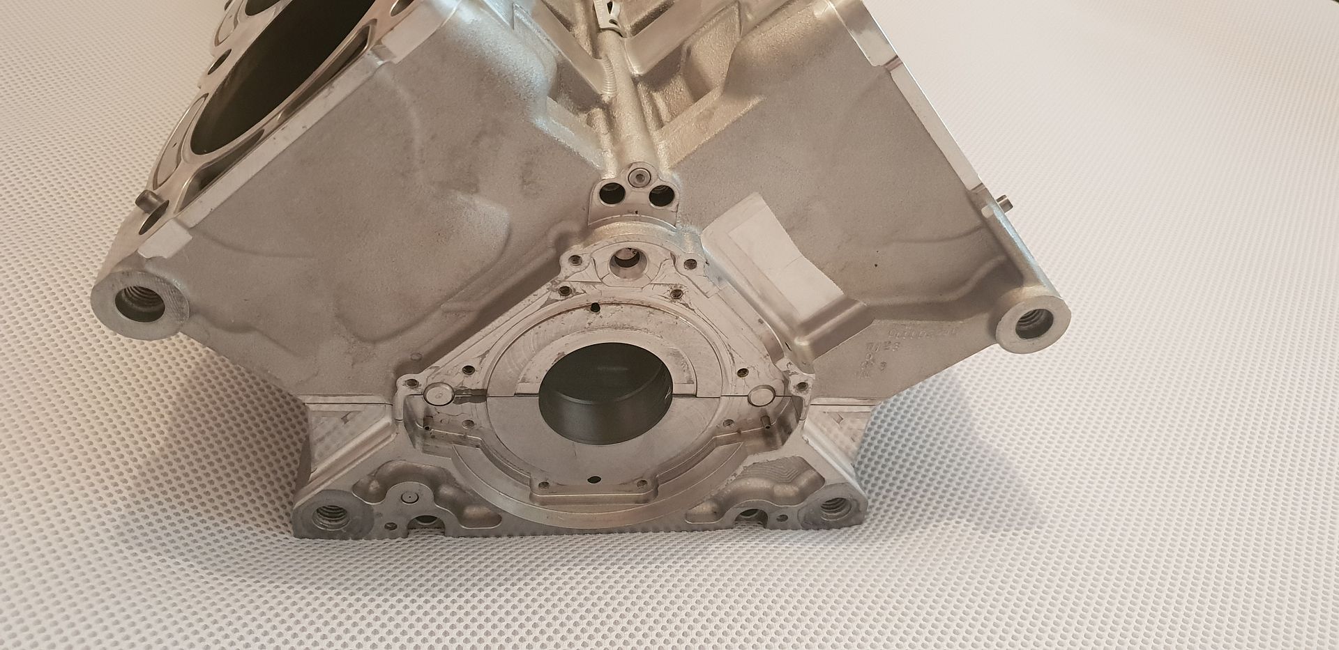
The main crank end-float is controlled via a single half moon thrust bearing on the flywheel end outer block face highlighted below,
And the recess in the actual block,
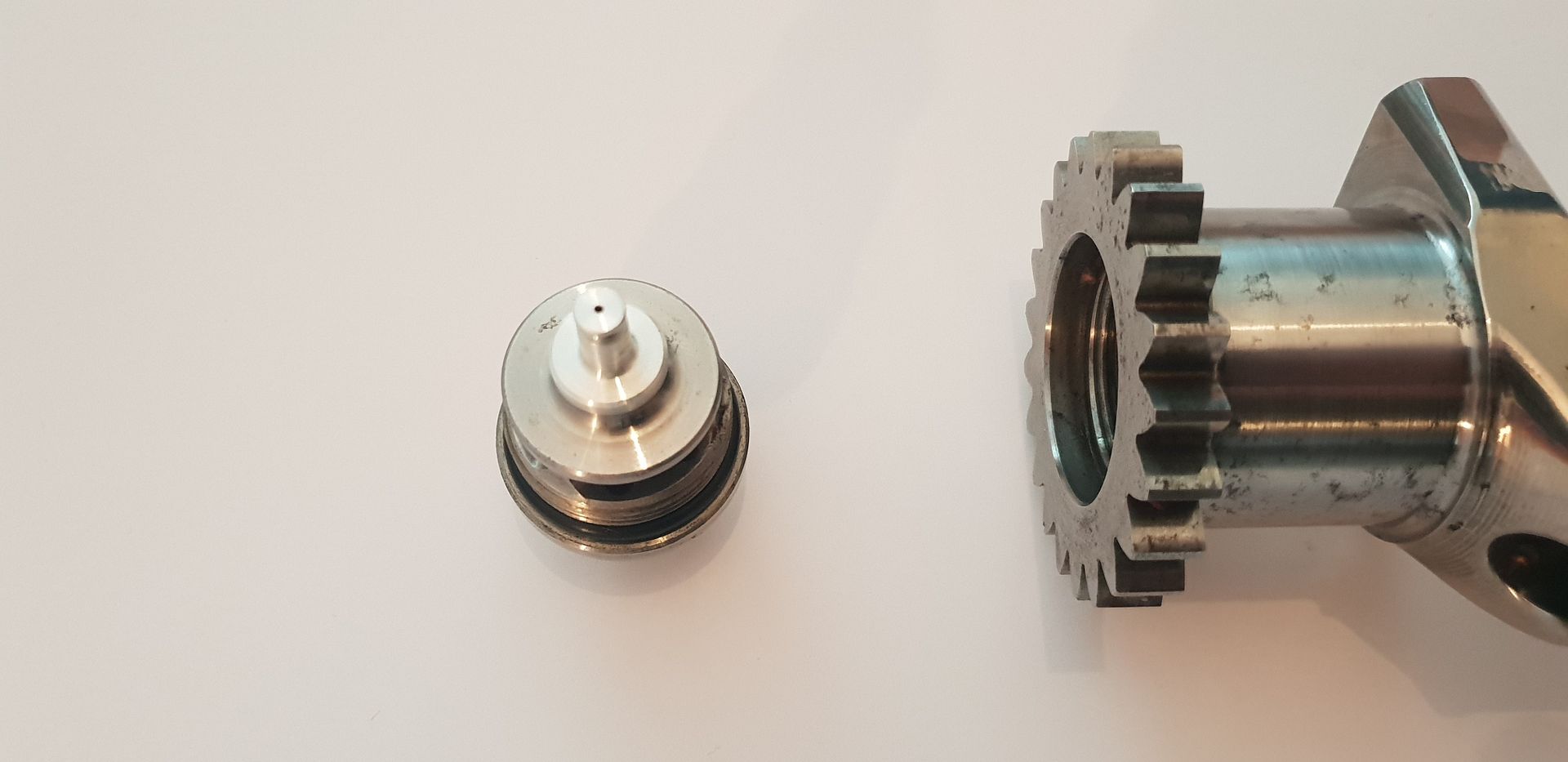
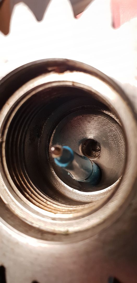
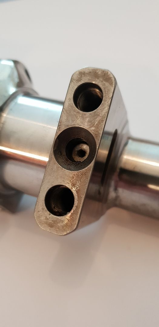
Onto the crank oiling - the oil enters the crank directly from the oil pump housing mounted onto the timing gear cover. It travels through the cover and into the crank nose fitting shown below,
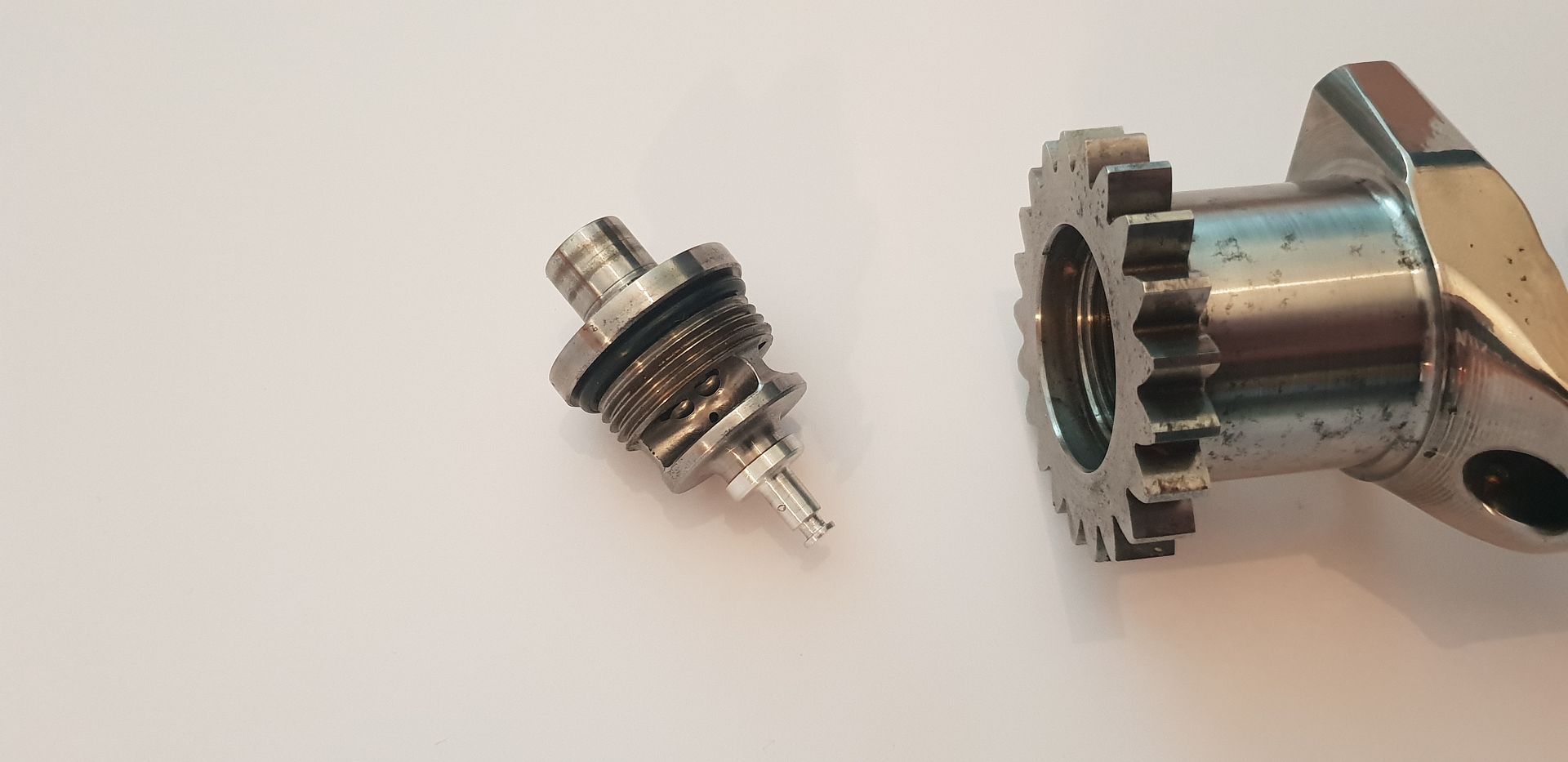
The fitting diffuses the oil flow radially, and prepares it for entry into the crank main drilling - a small jet also supplies oil to the first counter balance mass core in order to cool it(nose o-ring removed for clarity),
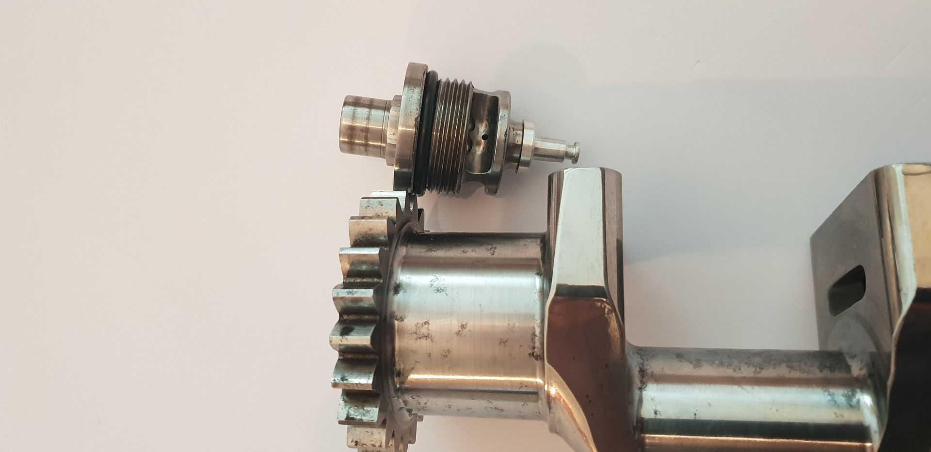
The drilling from crank nose supplies the main drilling,
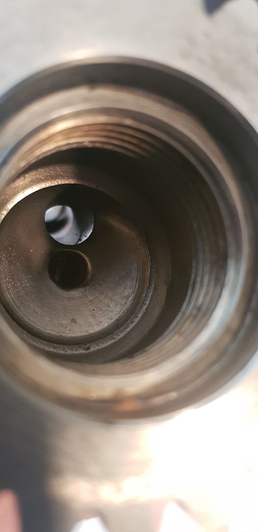
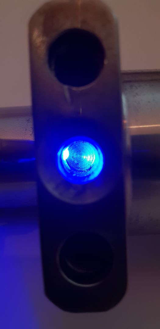
Shining an led into the first counter balance mass shows the small communal drilling from nose to provide cooling under the waisted plug, all the other counter balance masses rely on splash oil entering around the waisted plug to provide cooling.
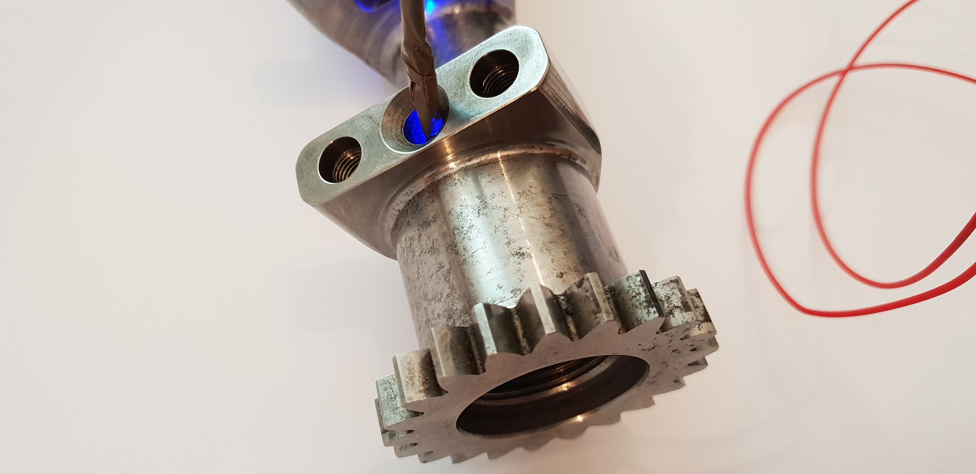
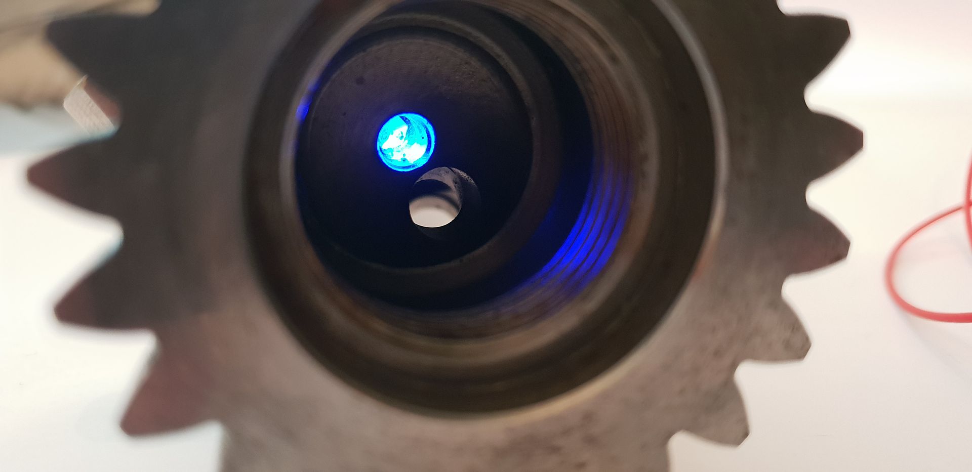
As you can see the other drillings in the counter balance masses are just blind holes to accept waisted plugs,
The plugs in question,
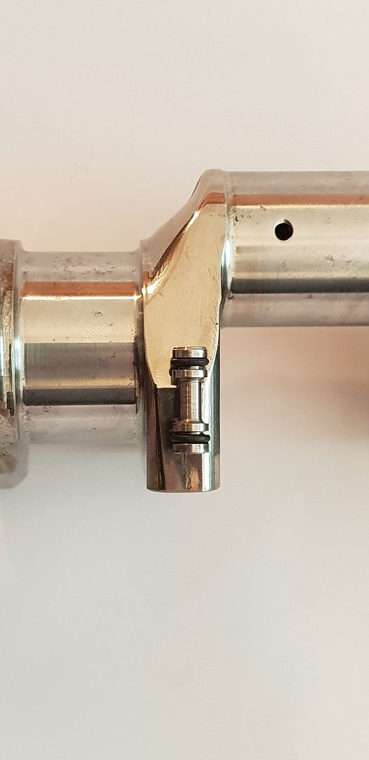
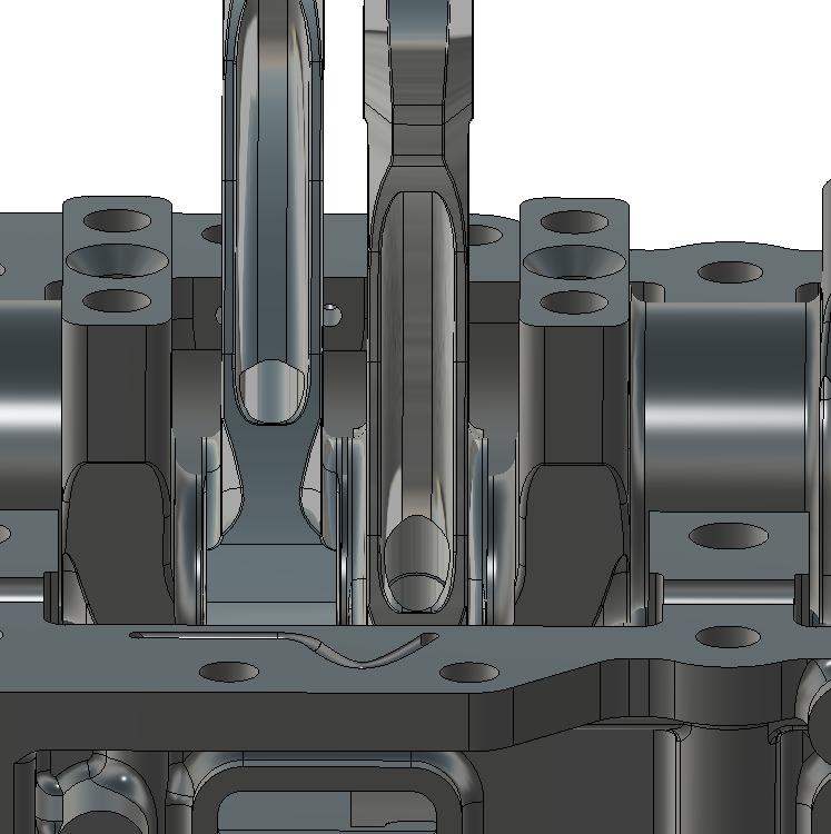
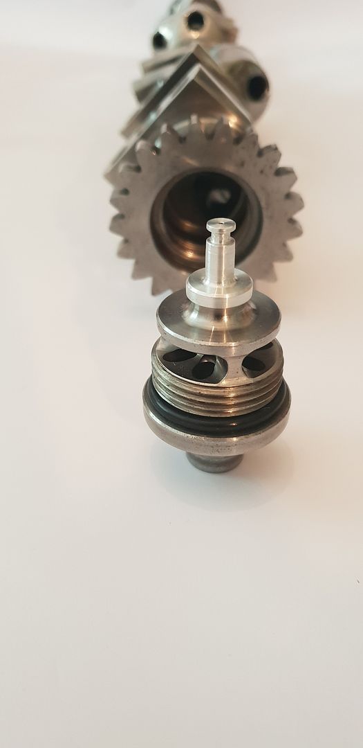
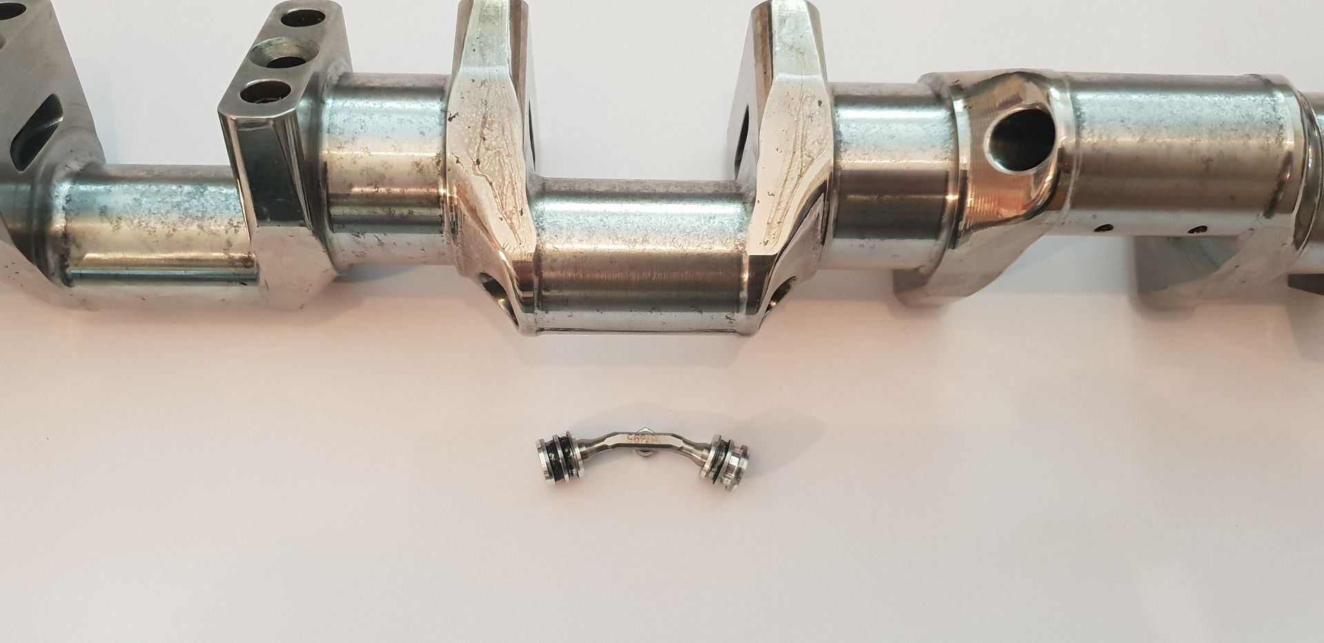
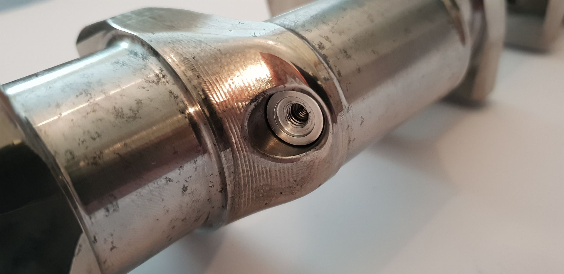
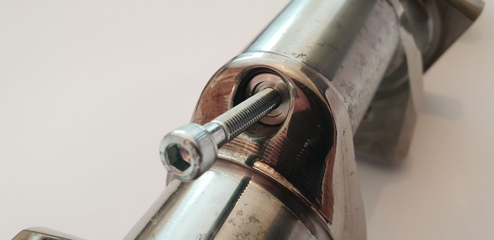
Because the main drillings need access for drilling in order for them all to connect to the supply at the nose the access drillings then need blanking in order to contain the oil pressure - this is done with two o-ringed aluminium bungs per web and are connected and locked in place internally with a titanium bridging brace as shown below(o-rings removed for ease of fitting),
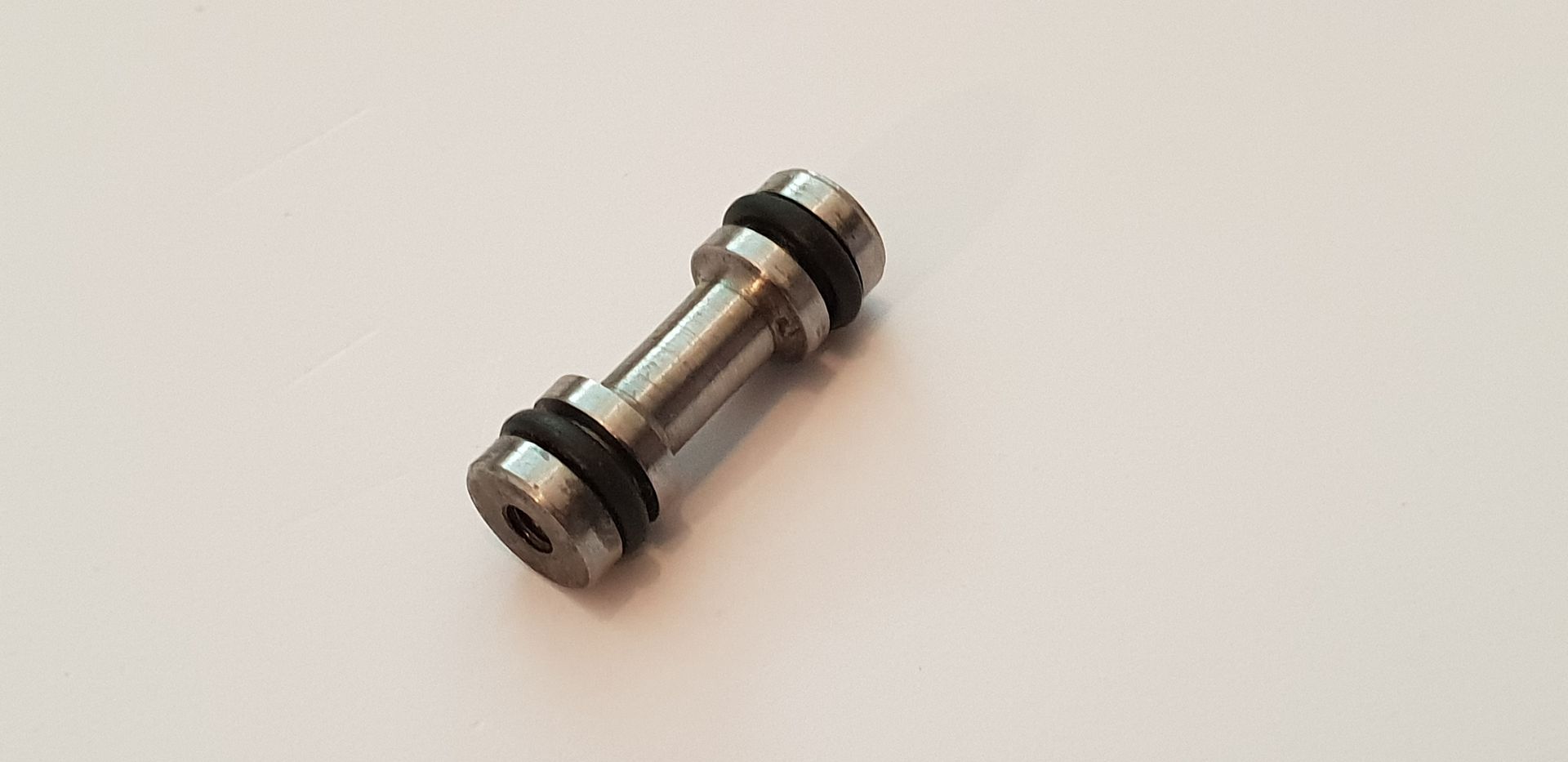
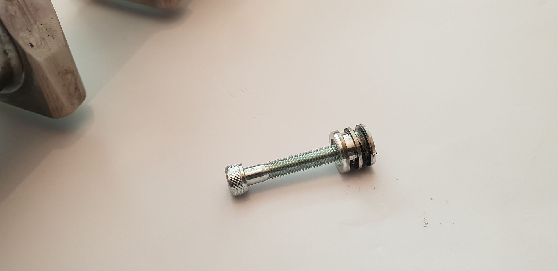
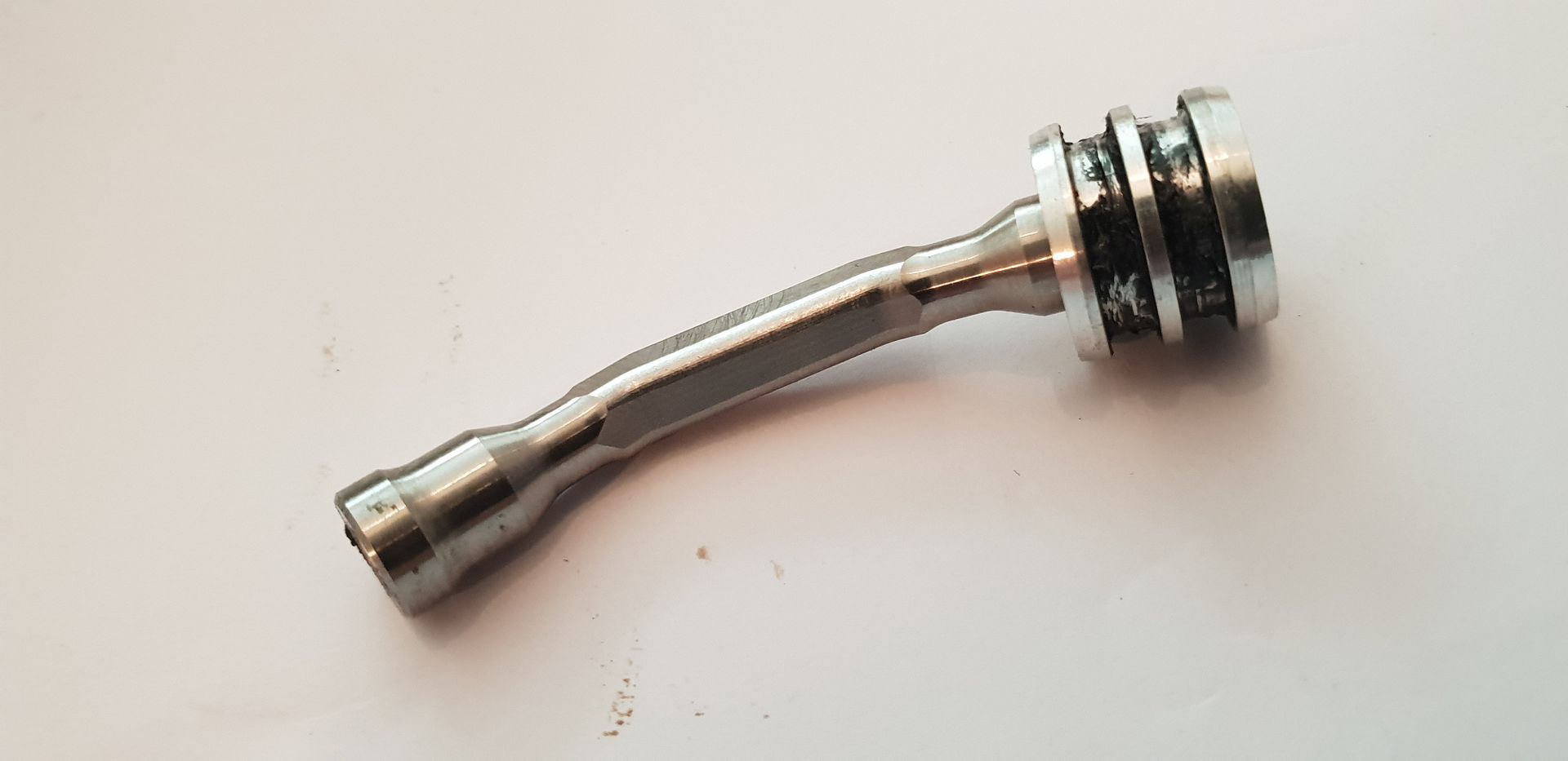
The bungs and bridging brace shown below,
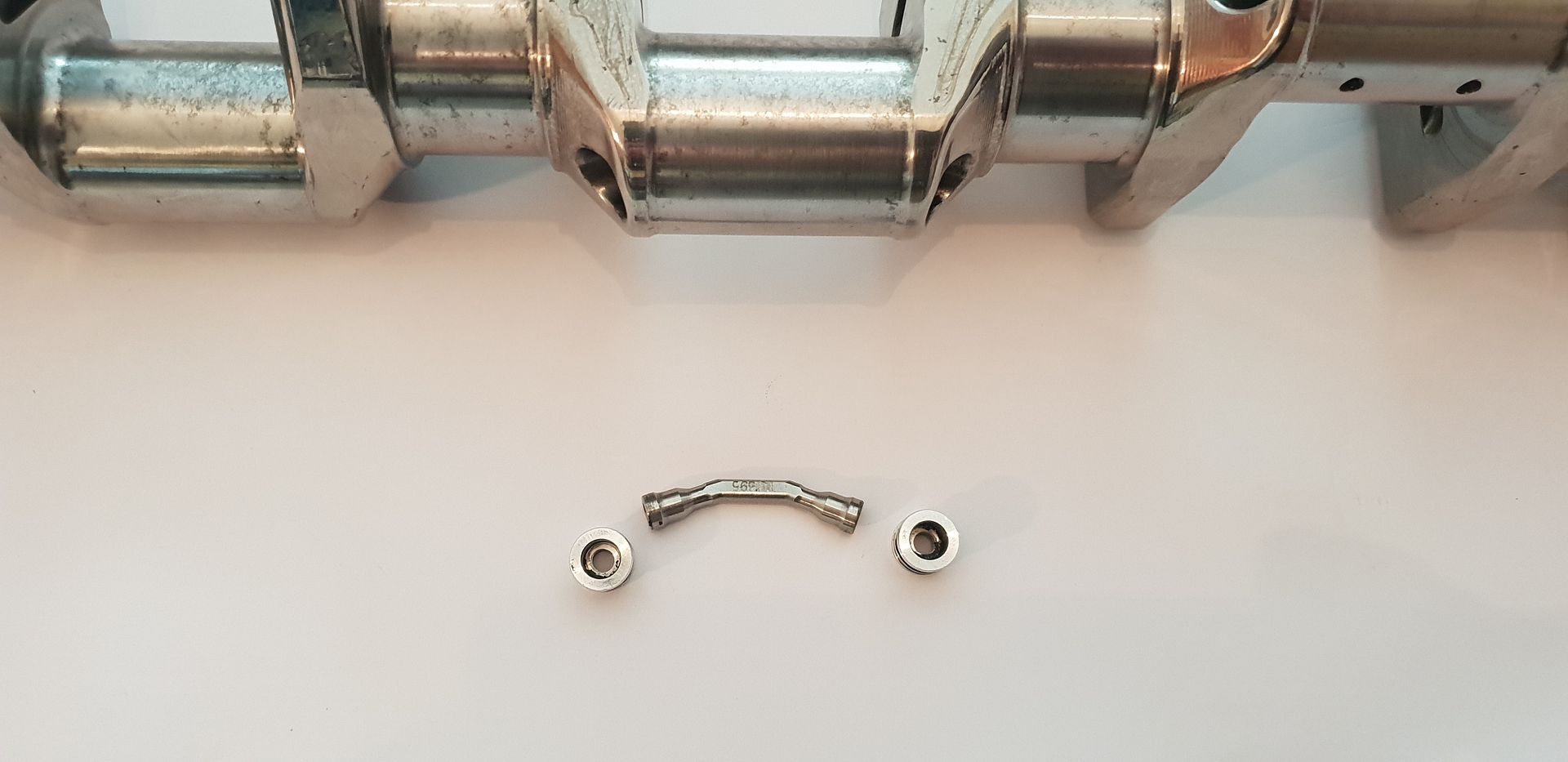
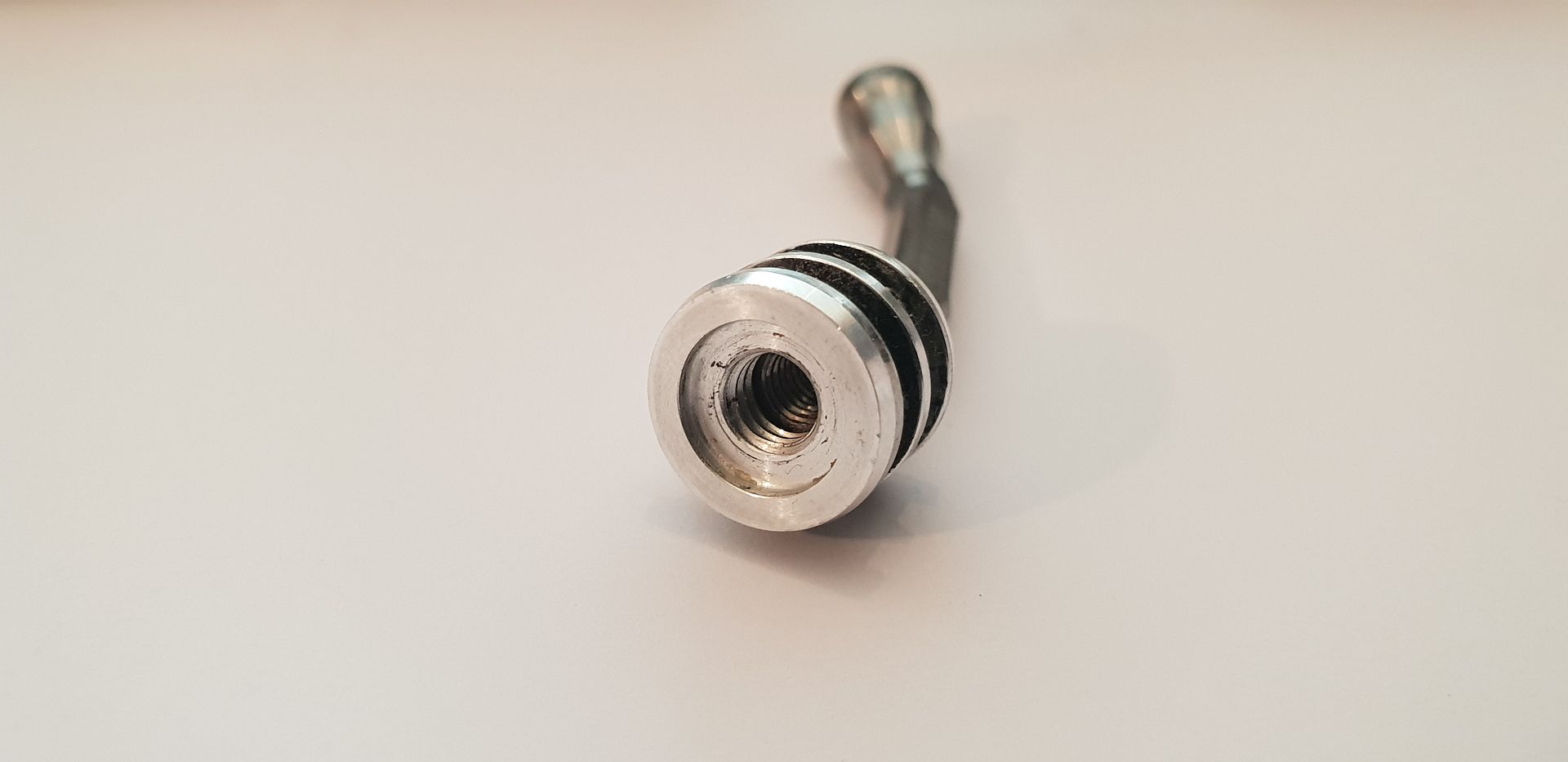
The bungs feature a larger thread than the bridge retaining bolt thread for ease of removal,
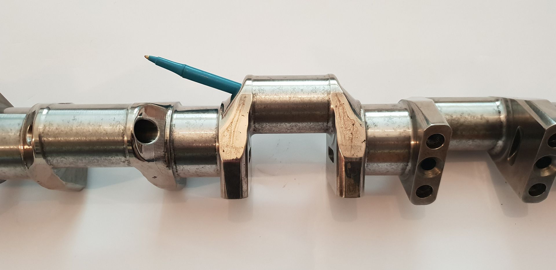
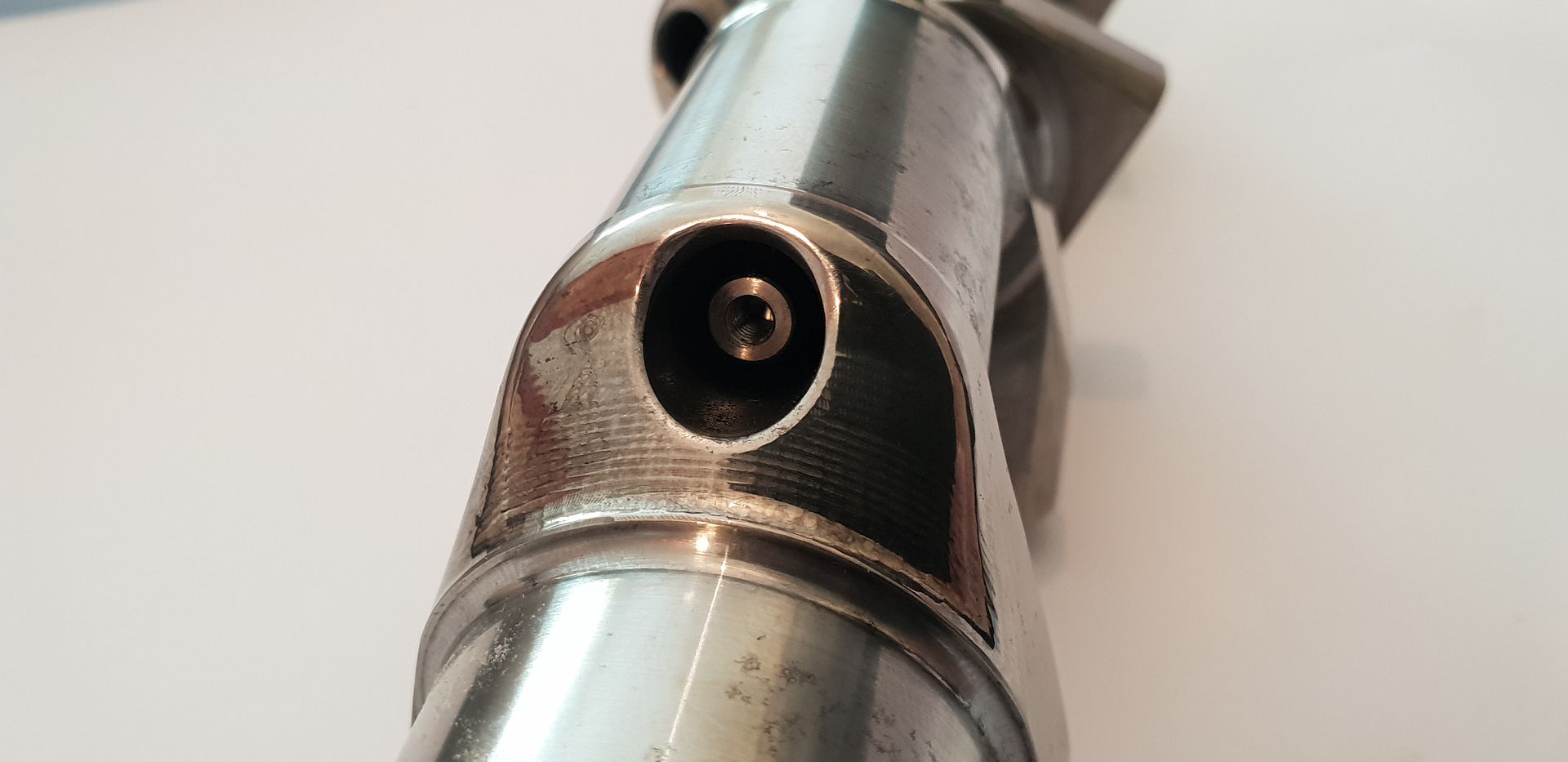
Fitted one side,
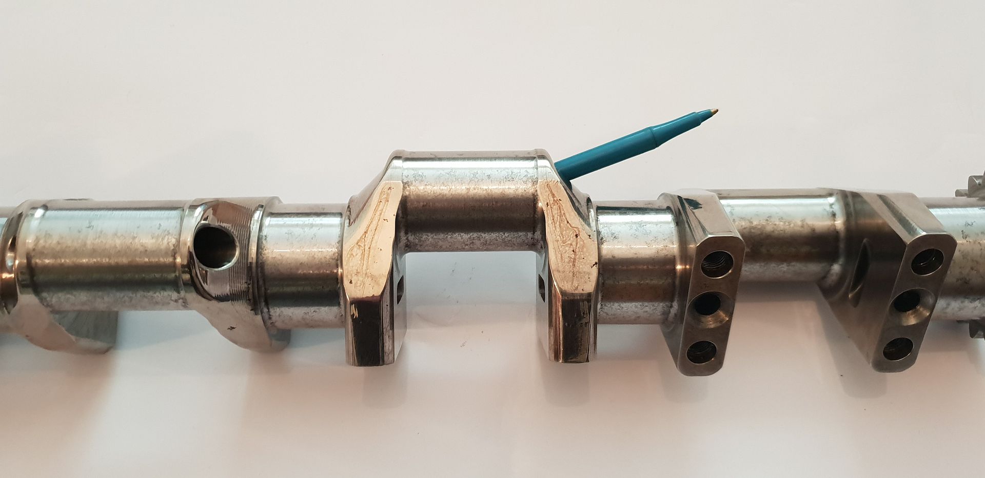
Bridge fitted,
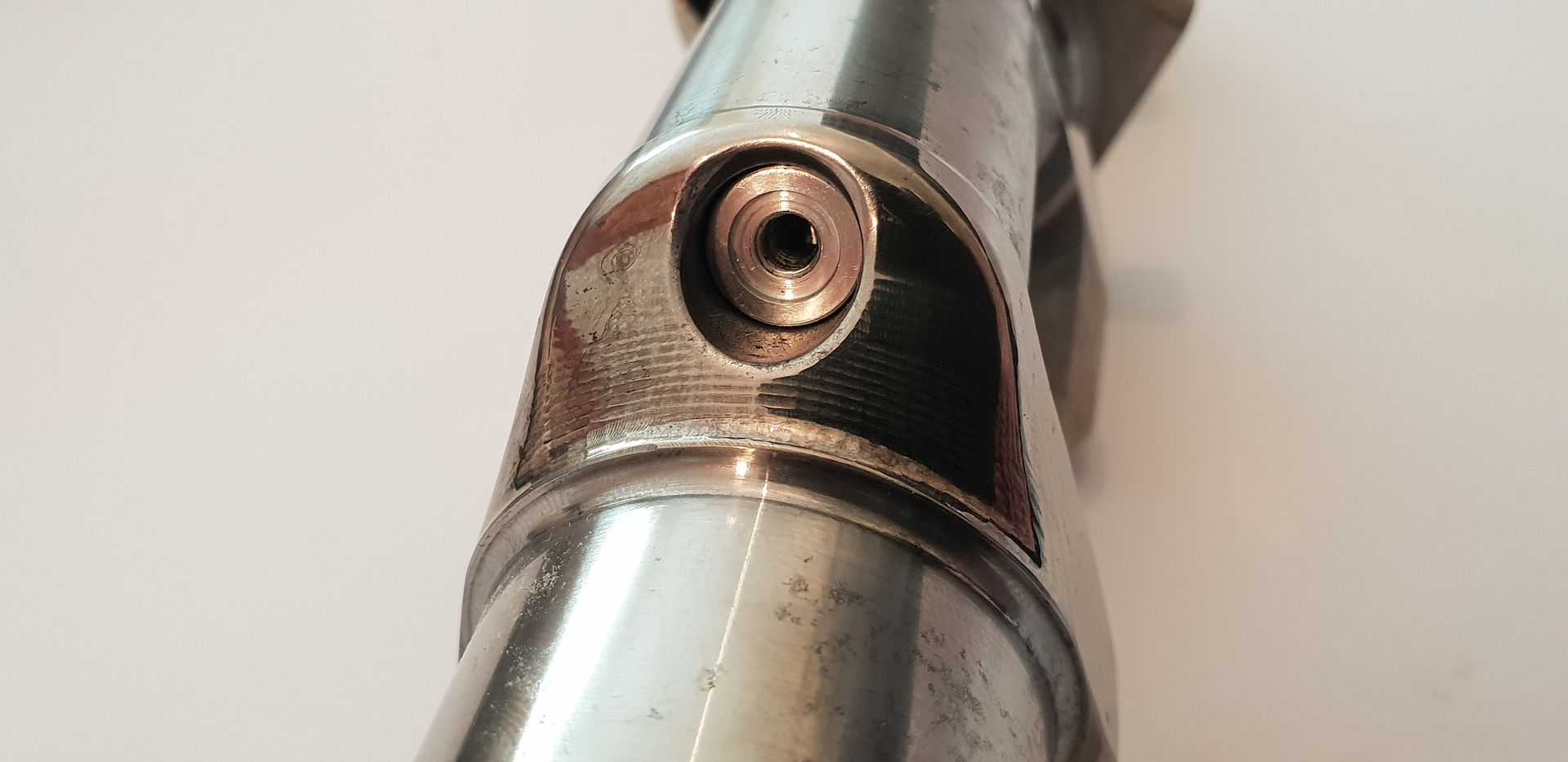
Second opposite bung fitted,
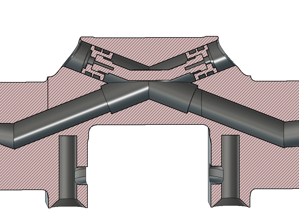
Cross-section,
Removal,
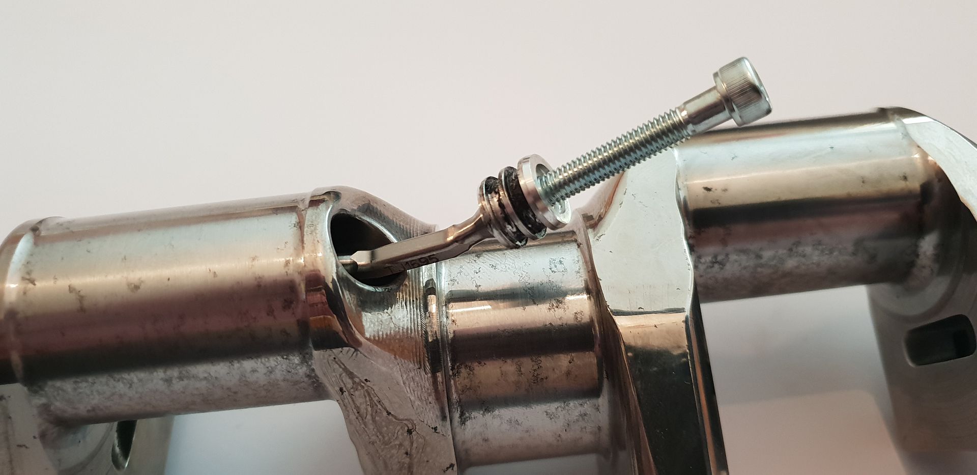
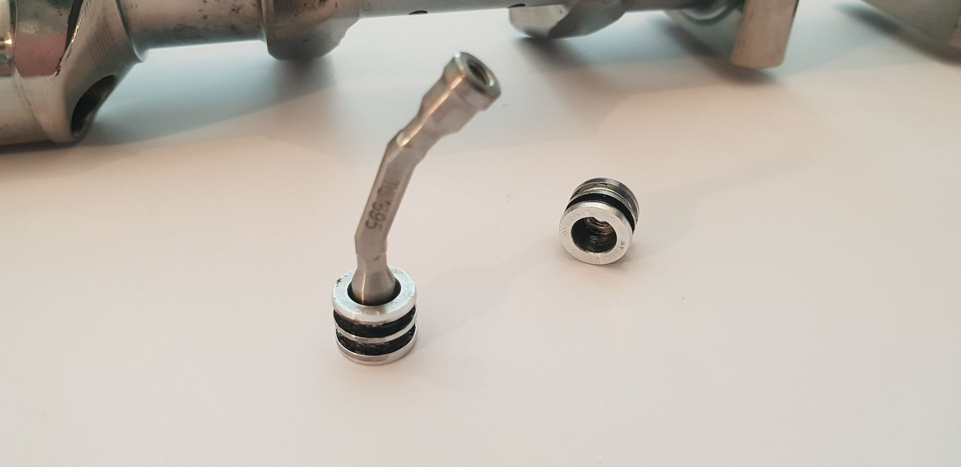
The bridge features a square cross-section in order to grip it on the bench with tightening the M4 holding the bung on one side first - once fitted inside crank, the second bung screw can be tightened as the crank stops the bridge assembly from turning,
To finish, the big end journals are 33.98mm in diameter, the main journals are 41.98mm in diameter, the stroke is 42mm(+/-.1mm) and the journal angular offsets are as follows taking the timing gear end journal to be zero degrees, and following around in a clockwise direction as you view crank from gearbox end - counting journal numbers coming towards you,
Timing End Journal 1 - 0 Degrees
Journal 2 - 64 degrees
Journal 3 - 134 Degrees
Journal 4 - 209 Degrees
Journal 5 - 265.5 Degrees
I have not yet looked at the angular dimensions bar cading it, but I suspect there is some machined in twist so that the crank runs true under power. I'll make the above angle offset call-outs a bit clearer with some cad next week.
Hope that fills in a few unanswered questions in terms of F1 Crankshafts....
All the Best,
Brian,