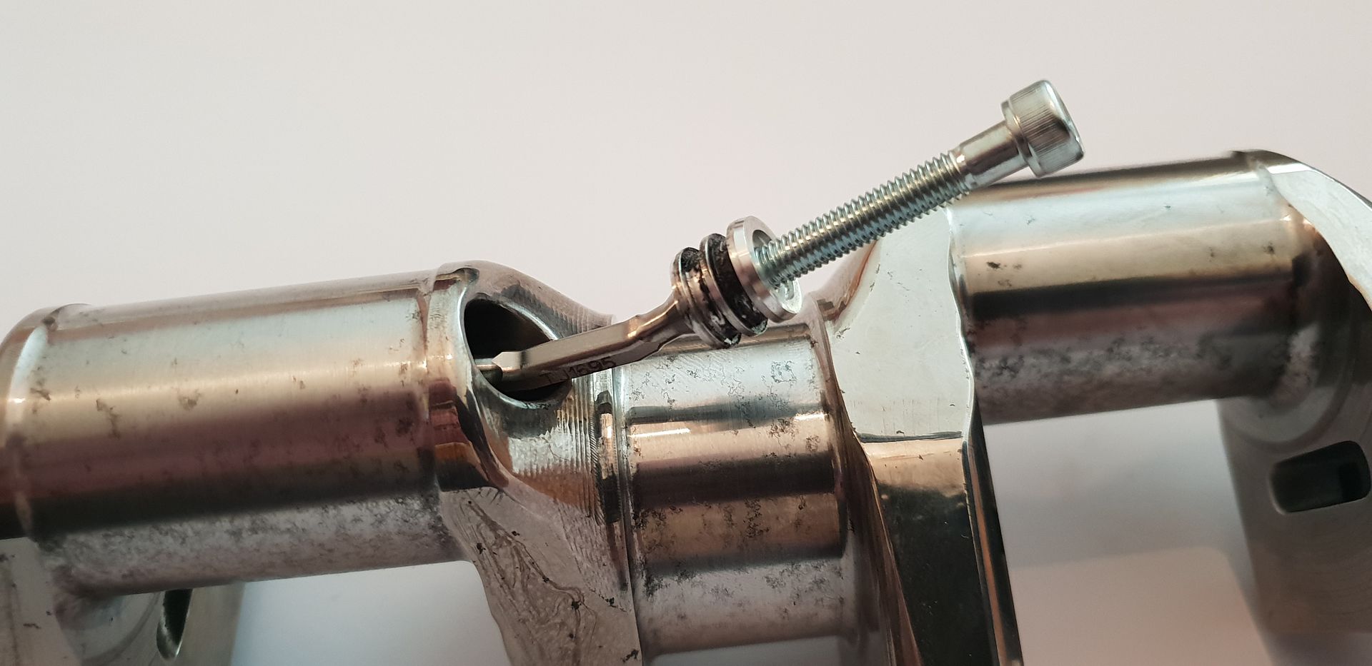
F1 Crankshaft, a closer look

All that has to do with the power train, gearbox, clutch, fuels and lubricants, etc. Generally the mechanical side of Formula One.
Brian.G
Brian.G
334
Joined: Fri Dec 10, 2010 10:52 pm
Location: Ireland

F1 Crankshaft, a closer look

Post

Another part under the spot light, this time the F1 Crankshaft.

In this thread I will be unlocking a few secrets hidden within this part - The F1 Crankshaft, mainly its construction, and some other features. For a good period of time a few things had always bothered me in terms of oil ways and so on.

The part below is from the Cosworth TJ V10 Engine - please be advised this crank has been in poor storage for the past while with the result it is now a display item only and will not be ran again. Its counterweights have also been removed but they are pretty inanimate objects in a way. With that in mind and ignoring the surface finish lets delve in and see what it has to offer.

Just to give a quick overview - F1 Crankshafts are oiled from one end - the oil travels along the crank internally, oiling each journal as it goes. In this case it is just the conrod journals that get fed from the internal oil drillings. The main journals get oiled from the block drillings as would a normal road engine. The key aspect in terms of F1 Crankshafts is keeping the oil supply to the big end journals and at the same time keeping the crankshaft cool as a single unit. Remember the F1 V10 Crankshaft is pretty long, and outputs approx 915hp from one end - so it has to be kept well in check in terms of cooling and lubrication...

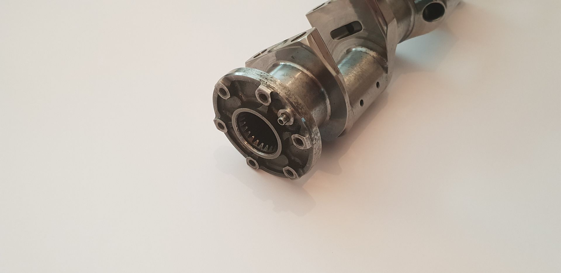
Onto the part itself - I'm starting first with a few basic overview shots, I'll touch on the finer details as we go,
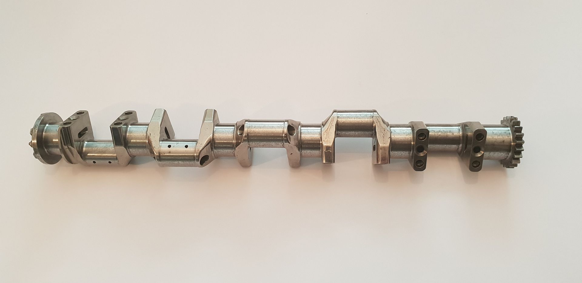
Image

Image

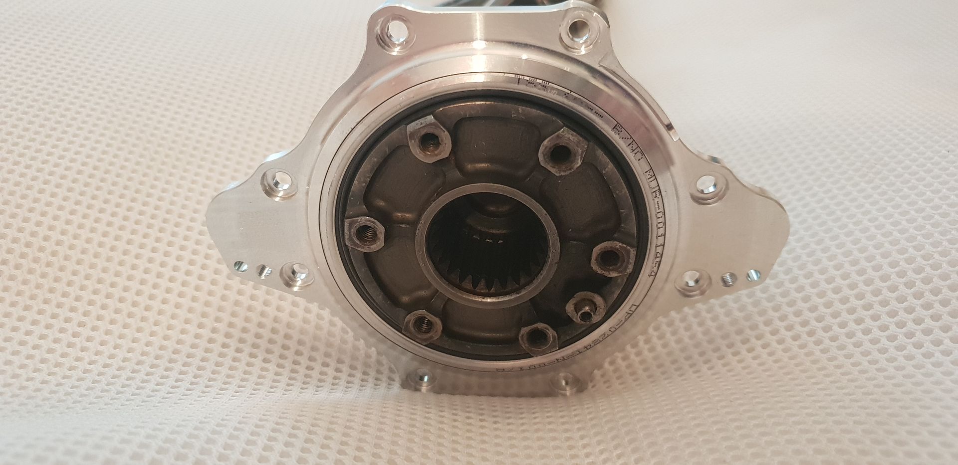
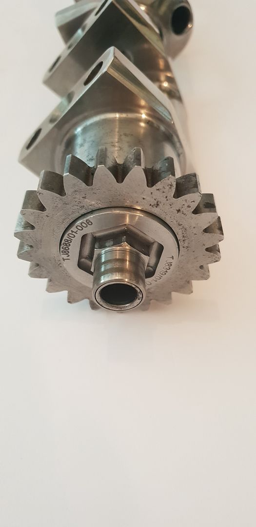
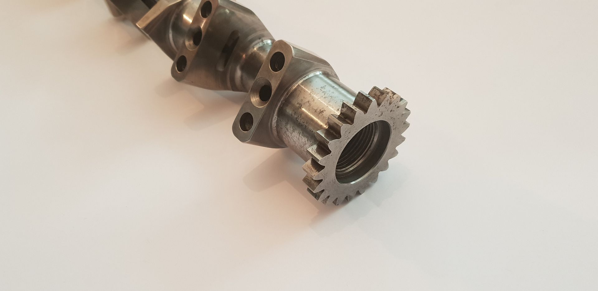
The output end,

Image

Image

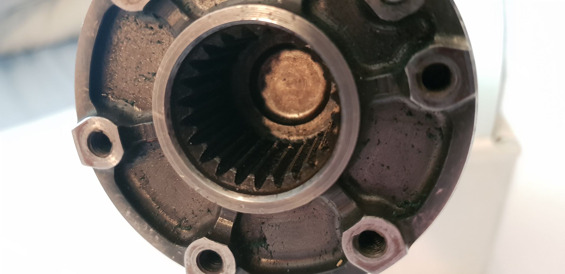
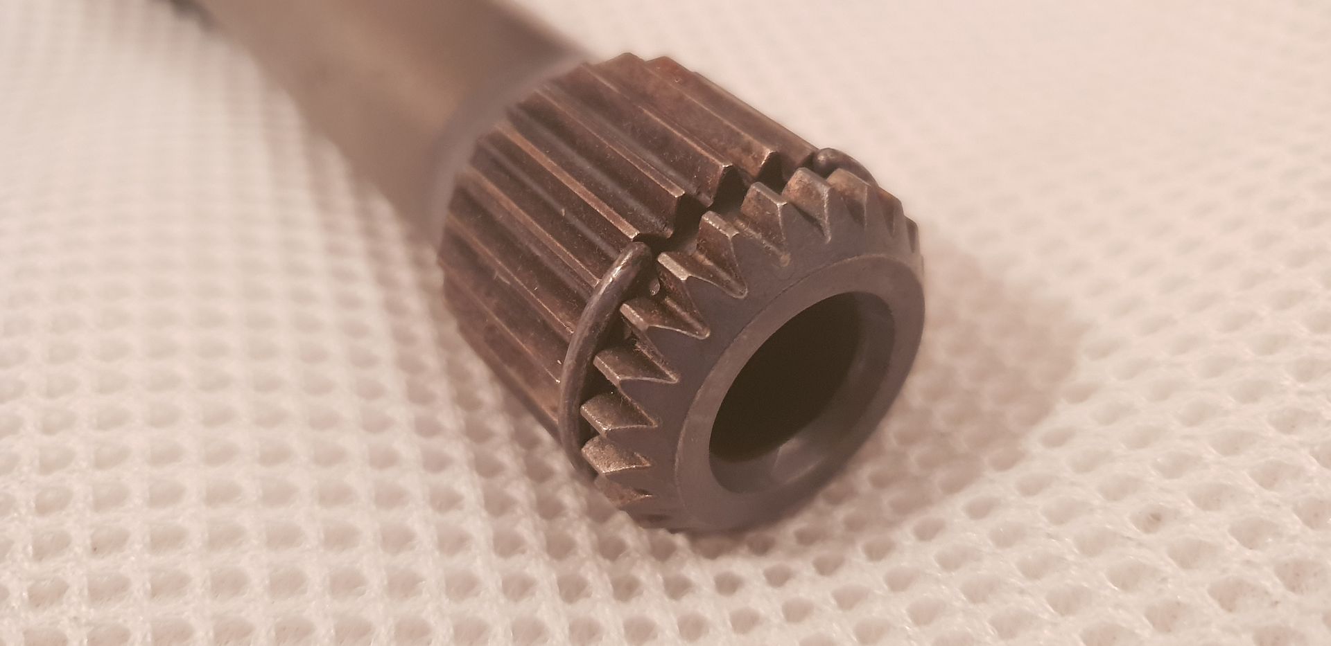
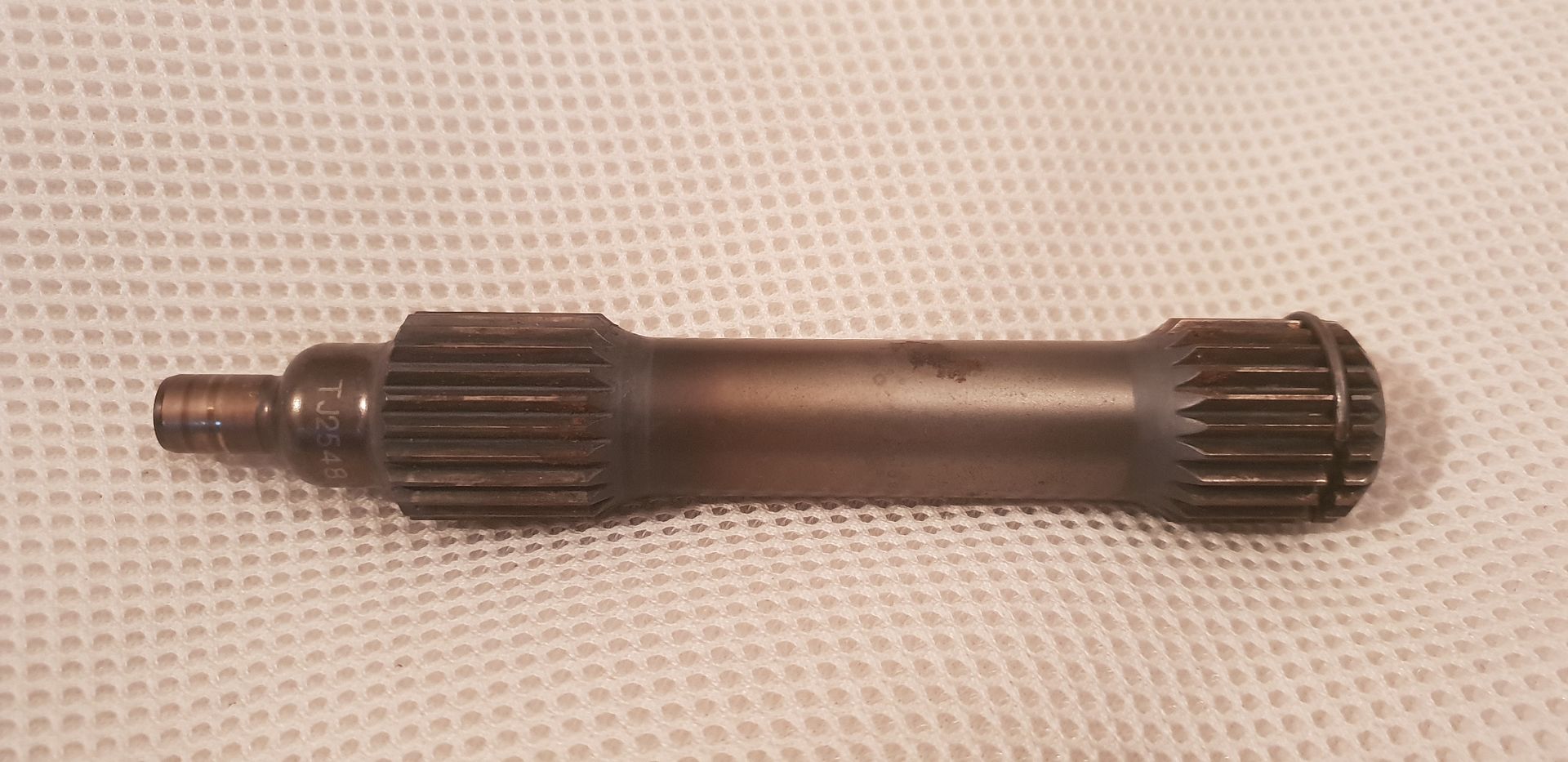
Into which the output gearbox shaft locates,
Image

Image

The end of the shaft locates into a pilot bearing in the gearbox and also of course transmits power to the clutch basket - which is hung off the gearbox bulkhead with twin angular contact bearings,
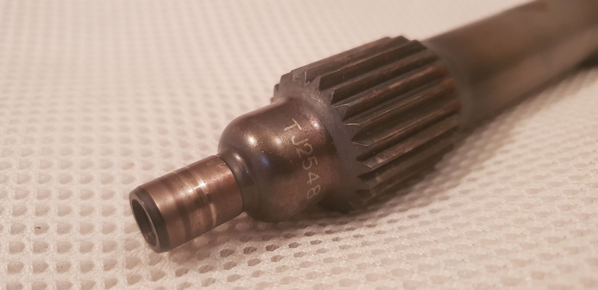
Image

The shaft is hollow and allows some compliance in the line of torsional vibrations present in the crankshaft, the splines either end also allow for any misalignment,
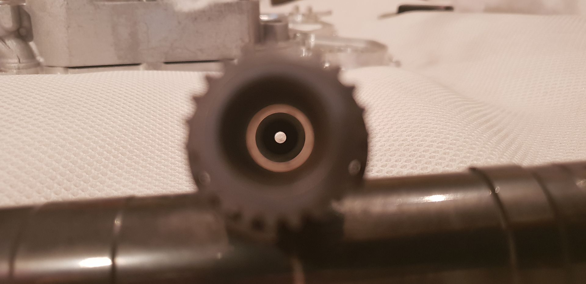
Image

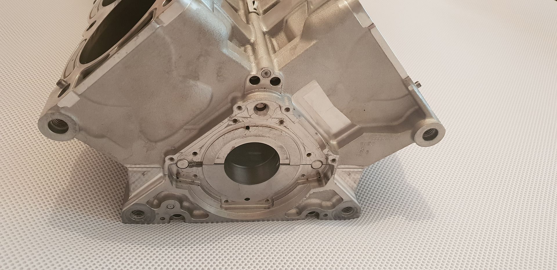
The crank seal locates too on this end - the far end has no crank seal of course as it is open to the timing gears,
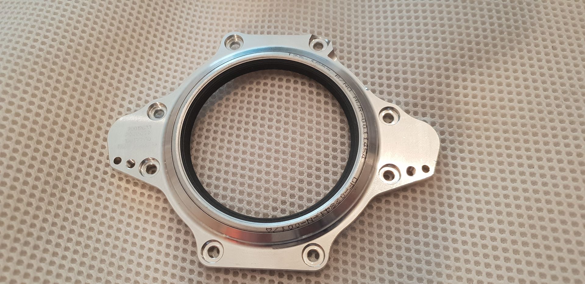
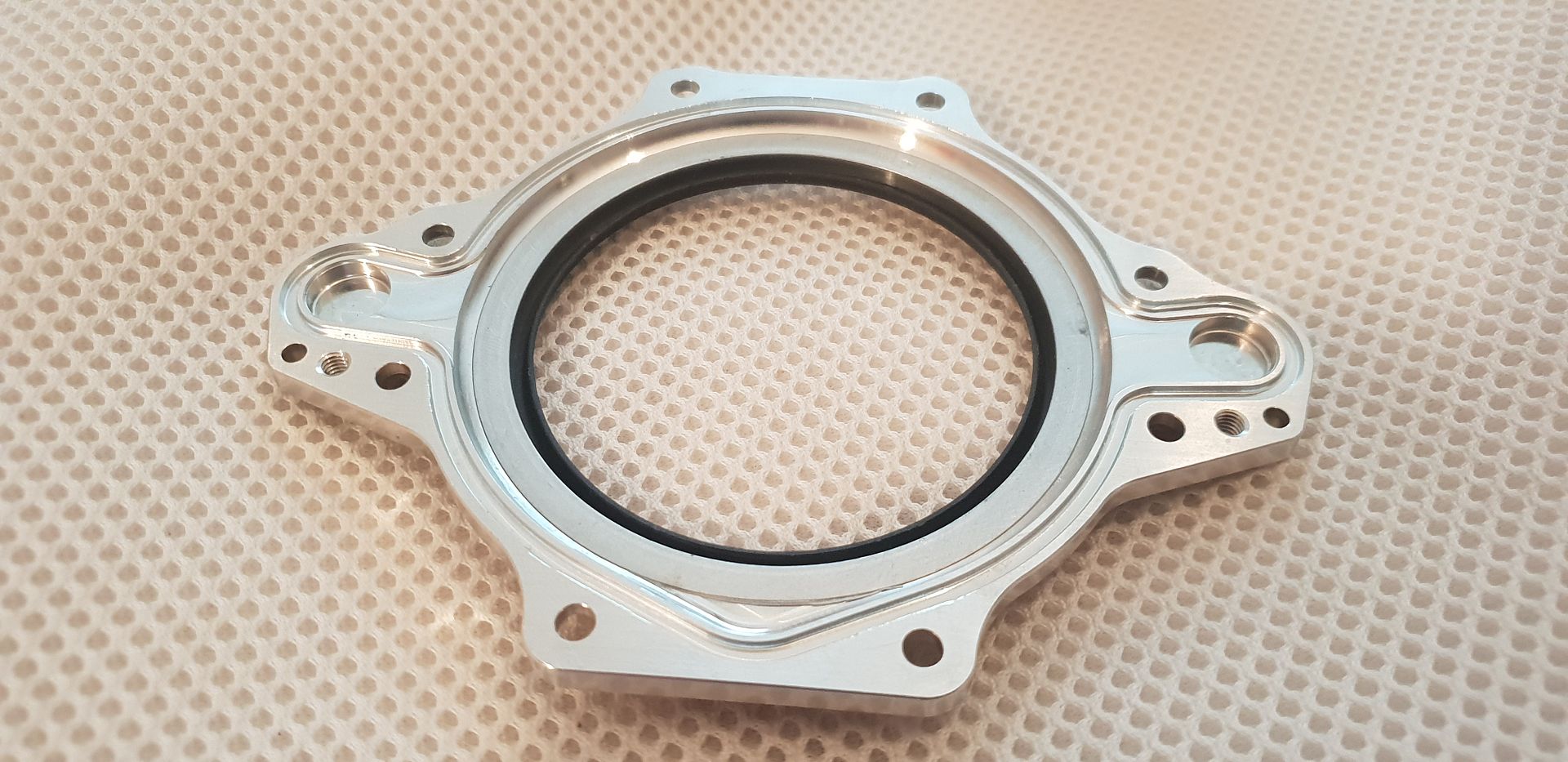
Image

Image

Its of the multi lip design and very stiff...keep in mind the crankcase is under vacuum,
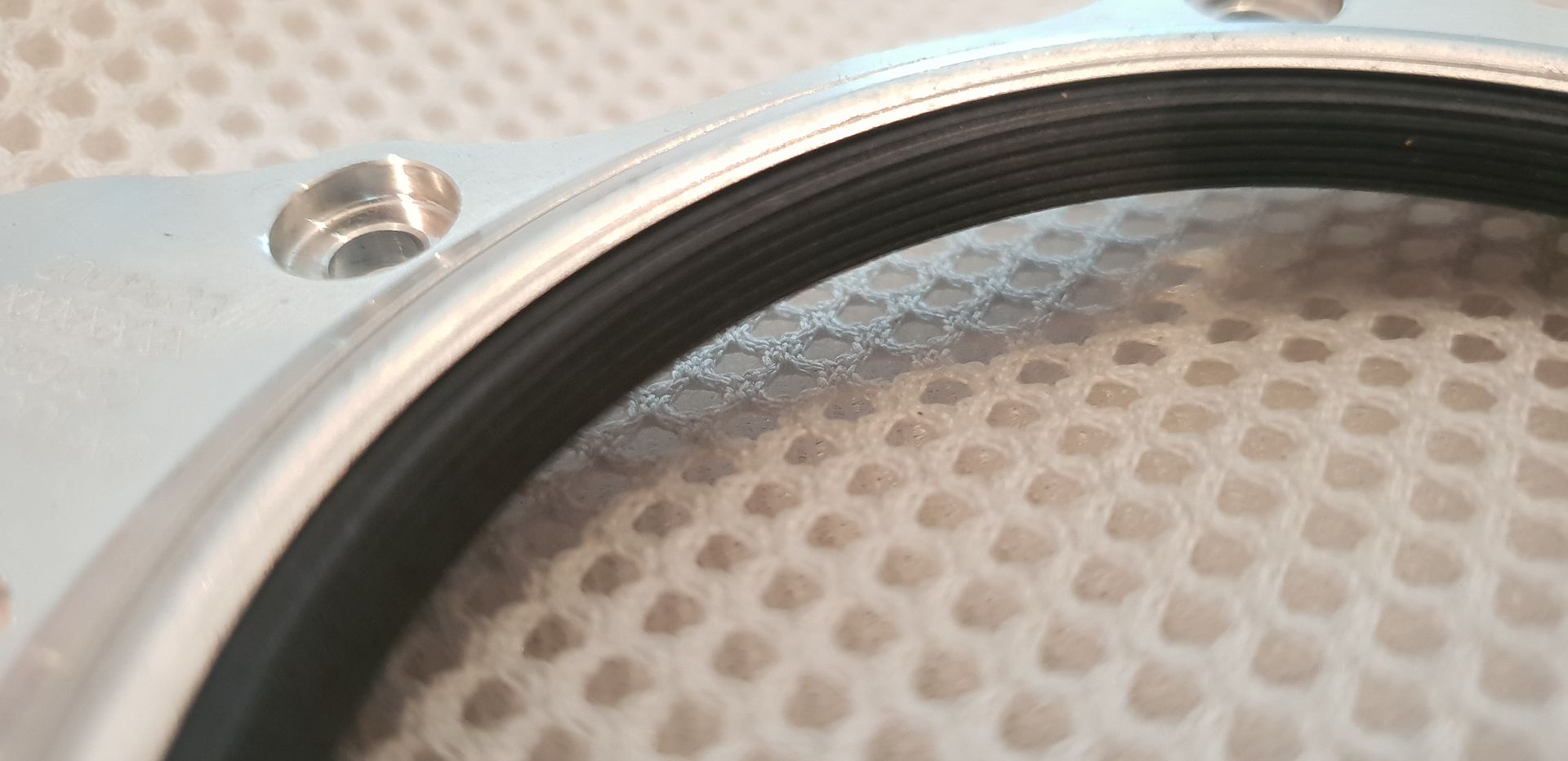
Image

Where it mounts to block,

Image

Fitted to crank,

Image

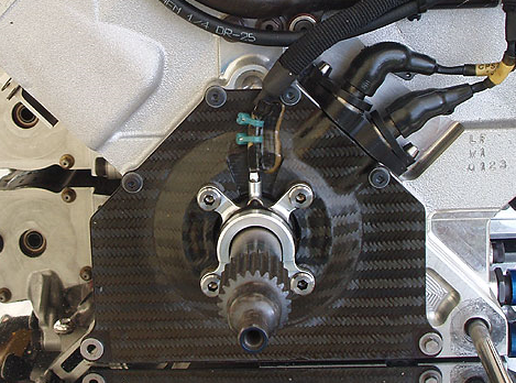
Onto this end also goes the toothed trigger ring for crank rpm monitoring,
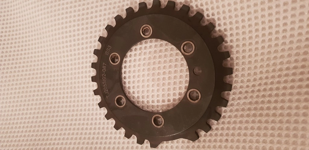
Image

The lot gets covered when mounted with a CF cover,
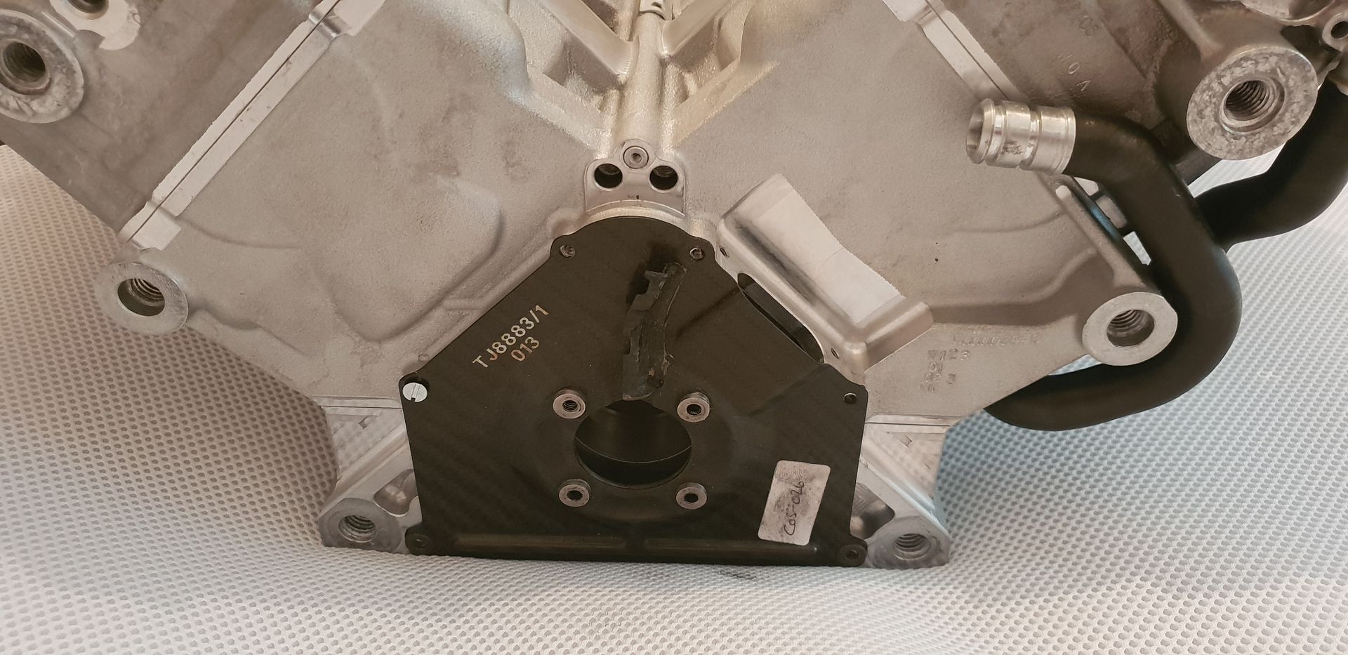
Image

Fully assembly below,

Image

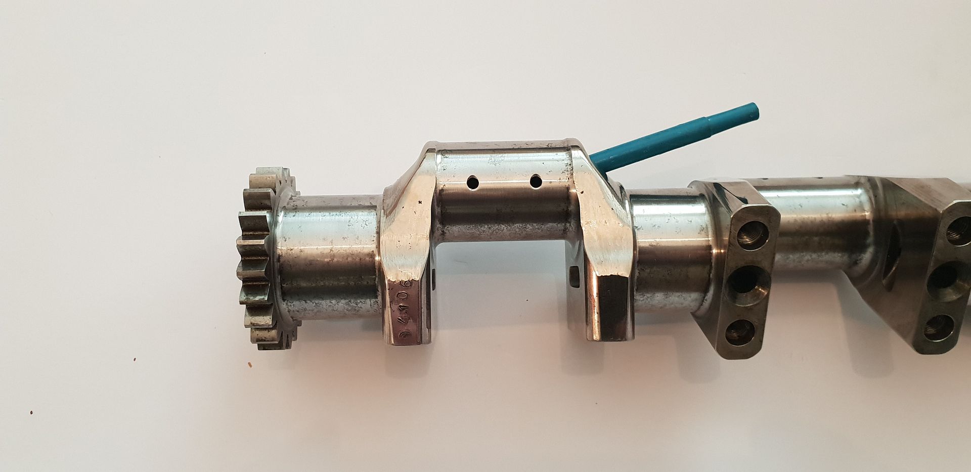
Moving up along the crank we can see the oil way drillings and journal fillet details,
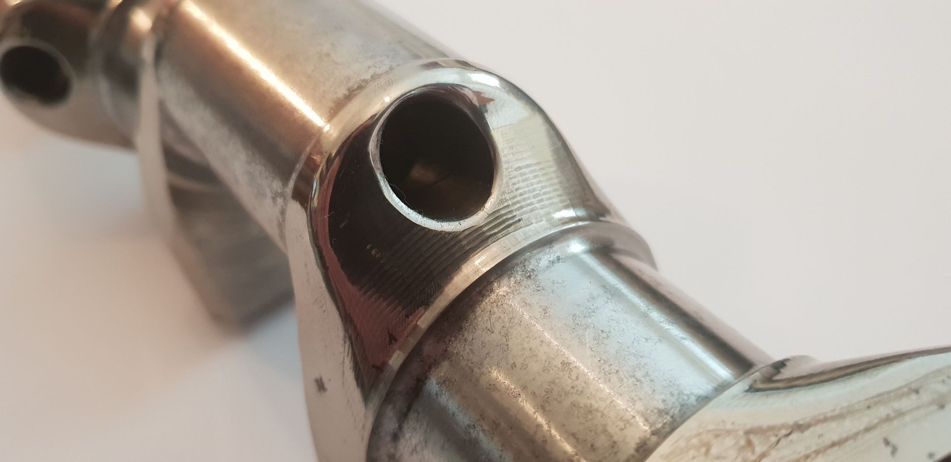
Image

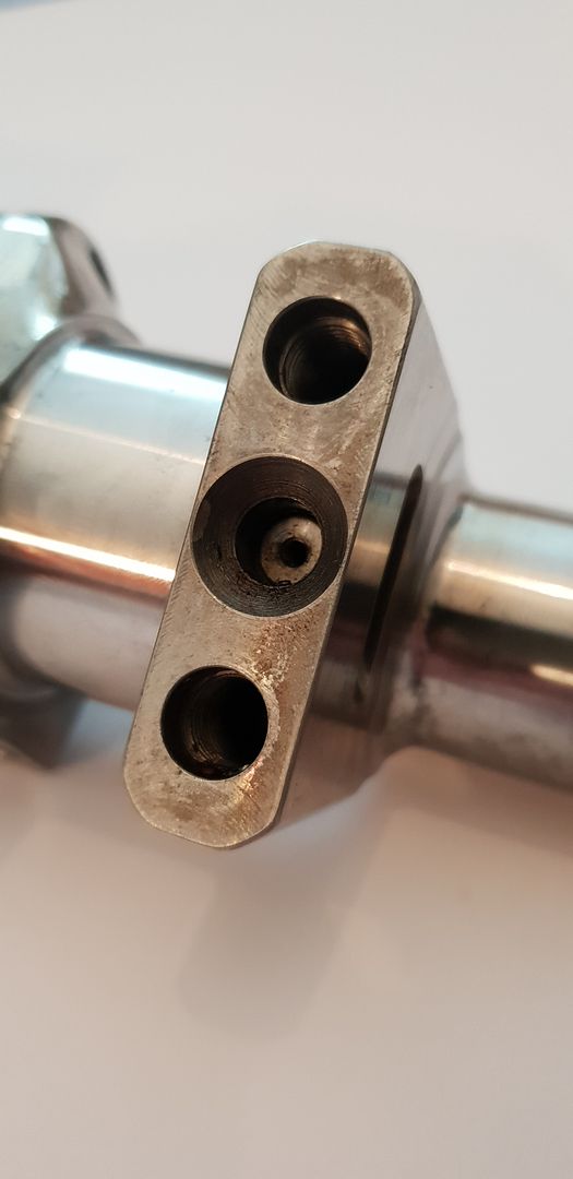
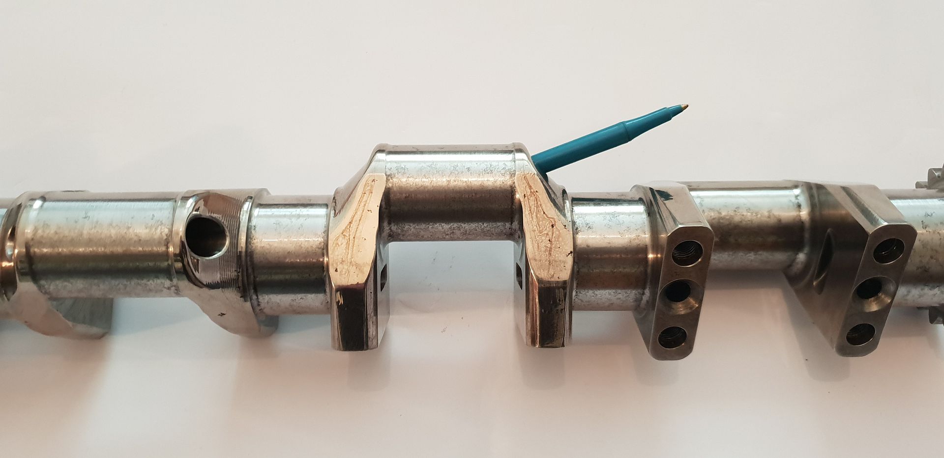
The counter weights bolt on to the locations below accurate location provided by a steel pin,
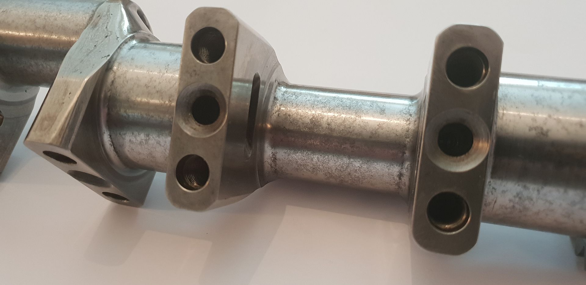
Image

The counterweight visible below bottom left,
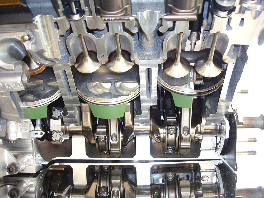
Image

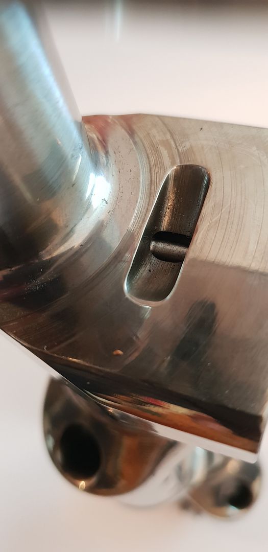
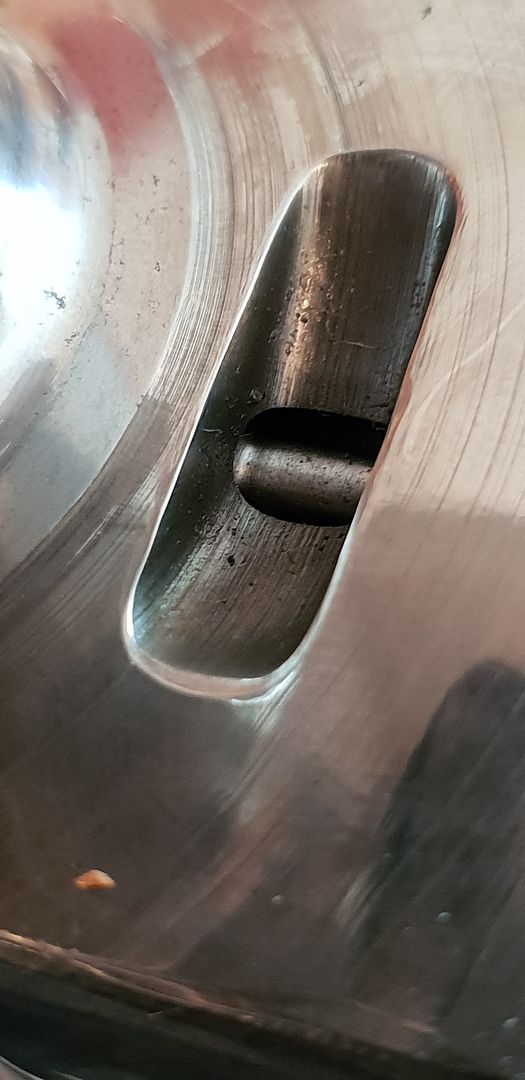
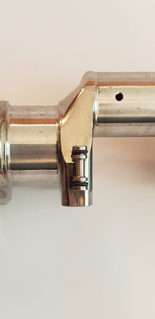
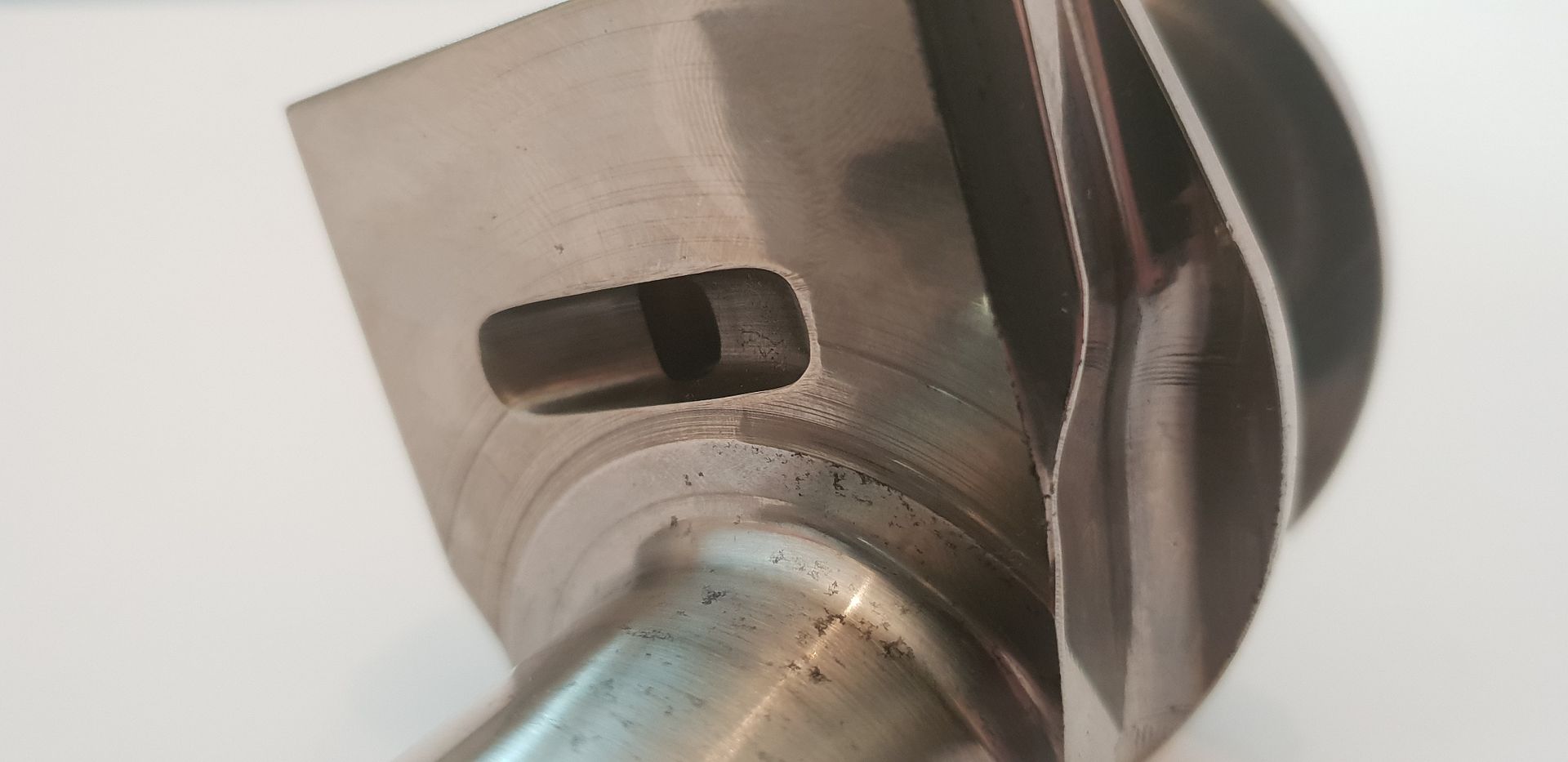
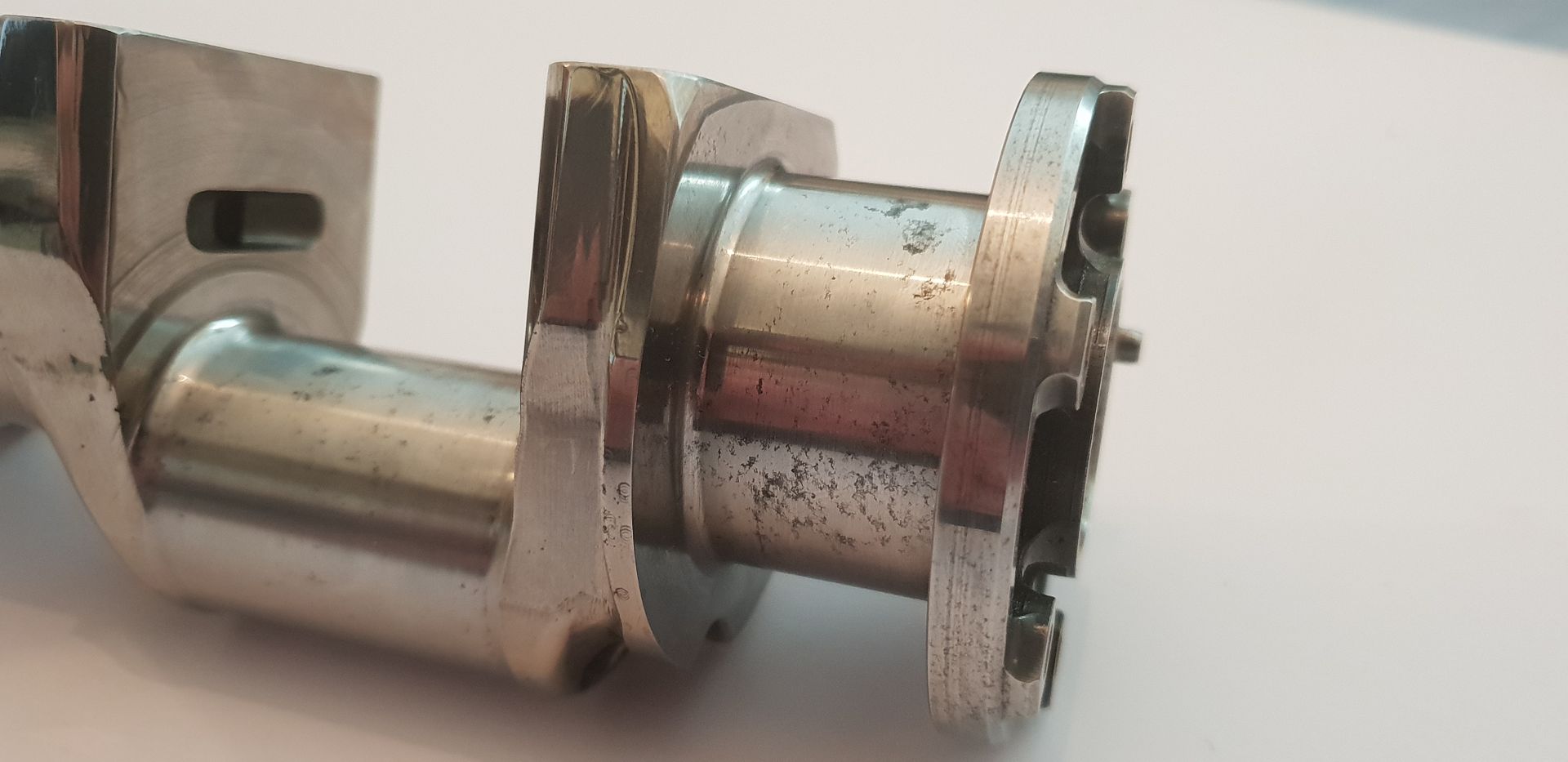
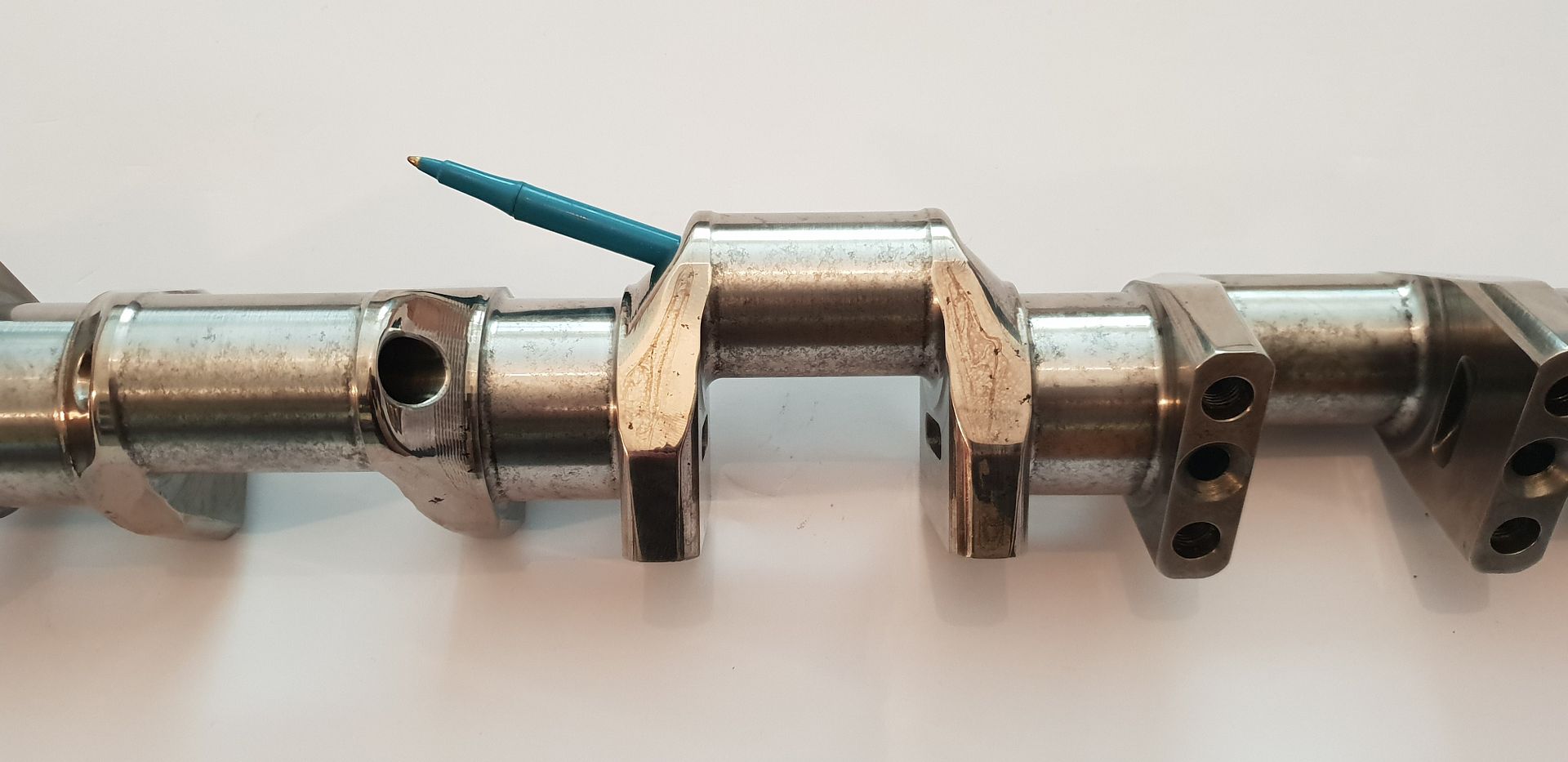
Again, notice the journal fillets...they are 4mm radius on big ends, and 2mm radius on main journals. This fillet detail is one of the most critical items on a high performance crank. Notice too the machined pocket - this is nothing more than a groove scooped out to meet a vertical drilling in the main crank mass - a waisted plug is inserted into this vertical drilling which in turn allows oil to circulate some what into the main mass in order to cool it - more on that later in thread,
Image

Image

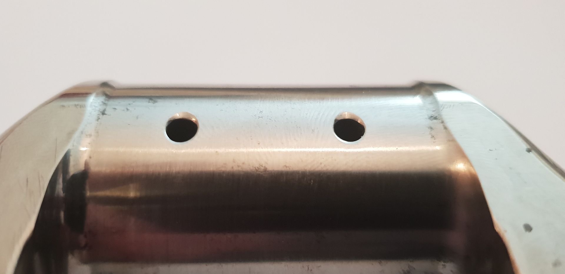
The big end drillings - each journal shares two rods - these holes enter into the internal oilway and are 3.5mm in diameter. They also have an eased trailing edge to promote oil wedge formation at low rpm in respect to the hydrodynamic oil film present between journal and shell pairs,
Image

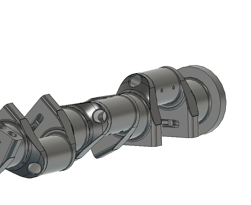
In the cad view below the crank rotates clockwise - clockwise when viewed from the timing gear end, therefore it is important to note that the big end journal drillings are located forward of top dead center and in the least area of downward force exerted by the conrod during the power stroke,
Image

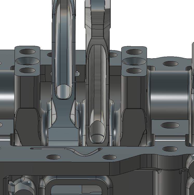
It is also worth noting that the rods are guided by the piston and have no thrust surfaces to guide them on the crank webs as shown below,
Image

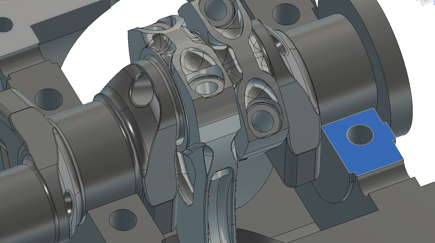
The main crank end-float is controlled via a single half moon thrust bearing on the flywheel end outer block face highlighted below,
Image

And the recess in the actual block,

Image

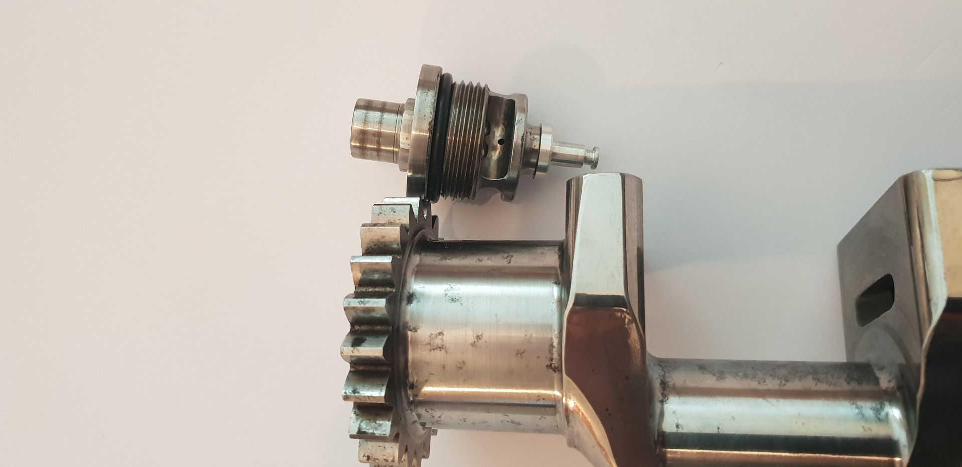
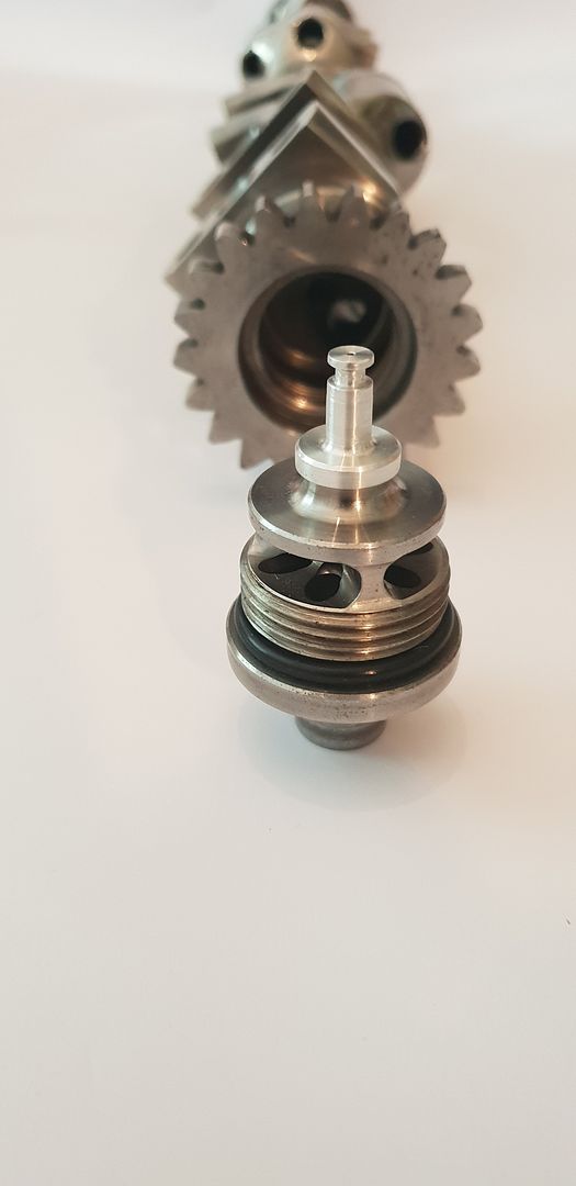
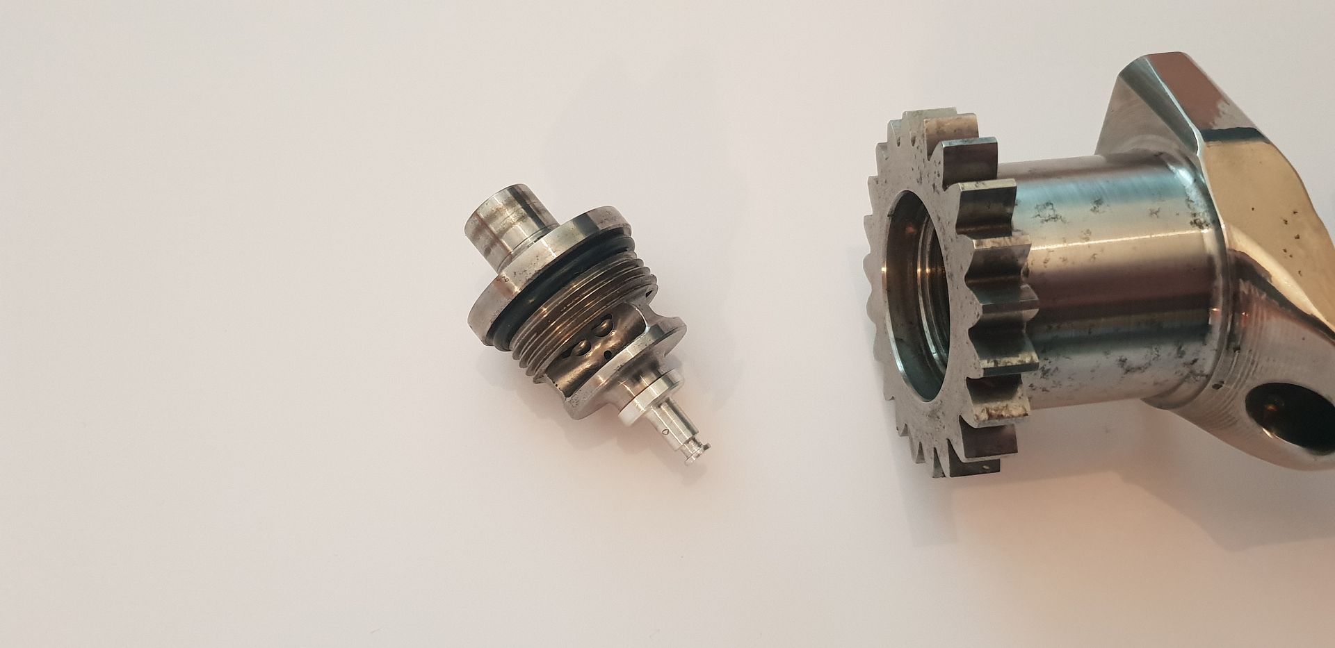
Onto the crank oiling - the oil enters the crank directly from the oil pump housing mounted onto the timing gear cover. It travels through the cover and into the crank nose fitting shown below,
Image

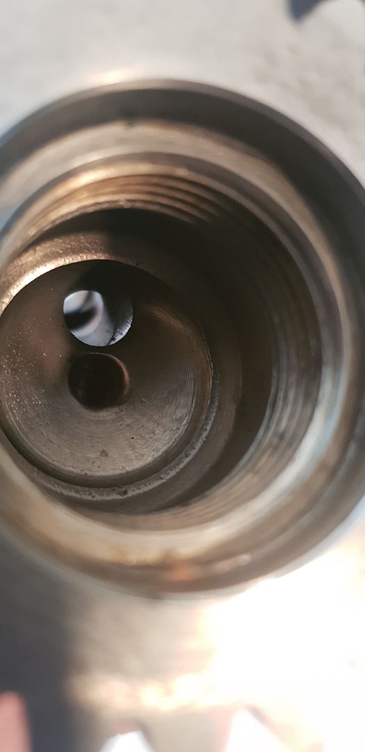
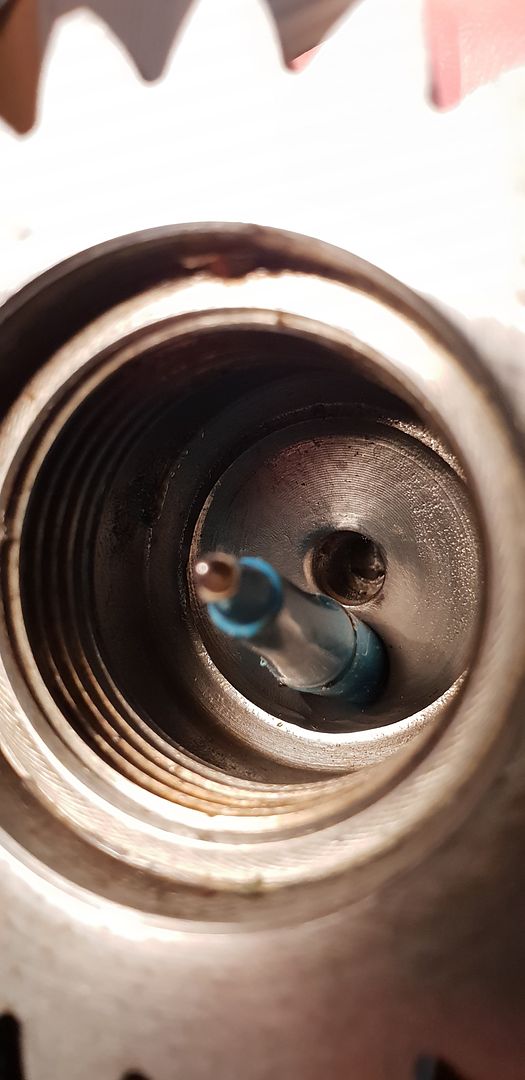
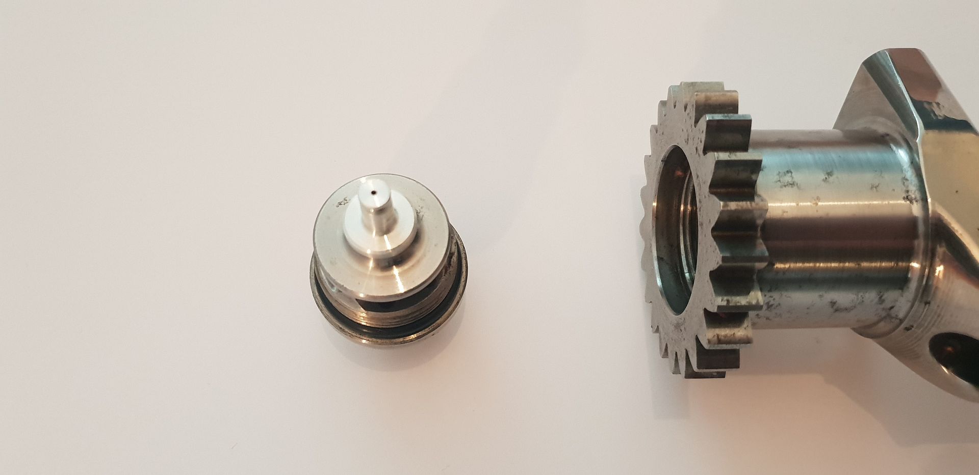
The fitting diffuses the oil flow radially, and prepares it for entry into the crank main drilling - a small jet also supplies oil to the first counter balance mass core in order to cool it(nose o-ring removed for clarity),

Image

Image

Image

Image

Image

Image

The drilling from crank nose supplies the main drilling,
Image

Image

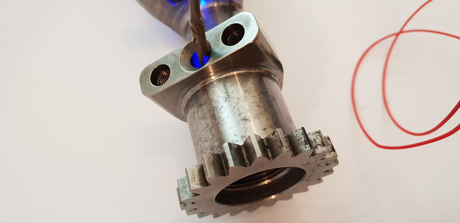
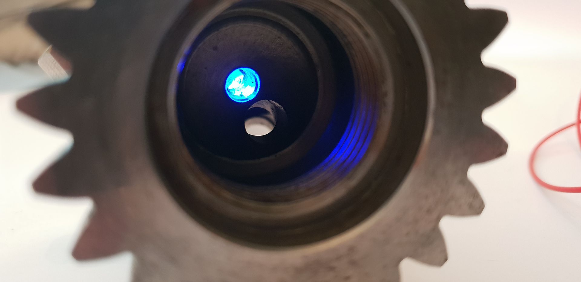
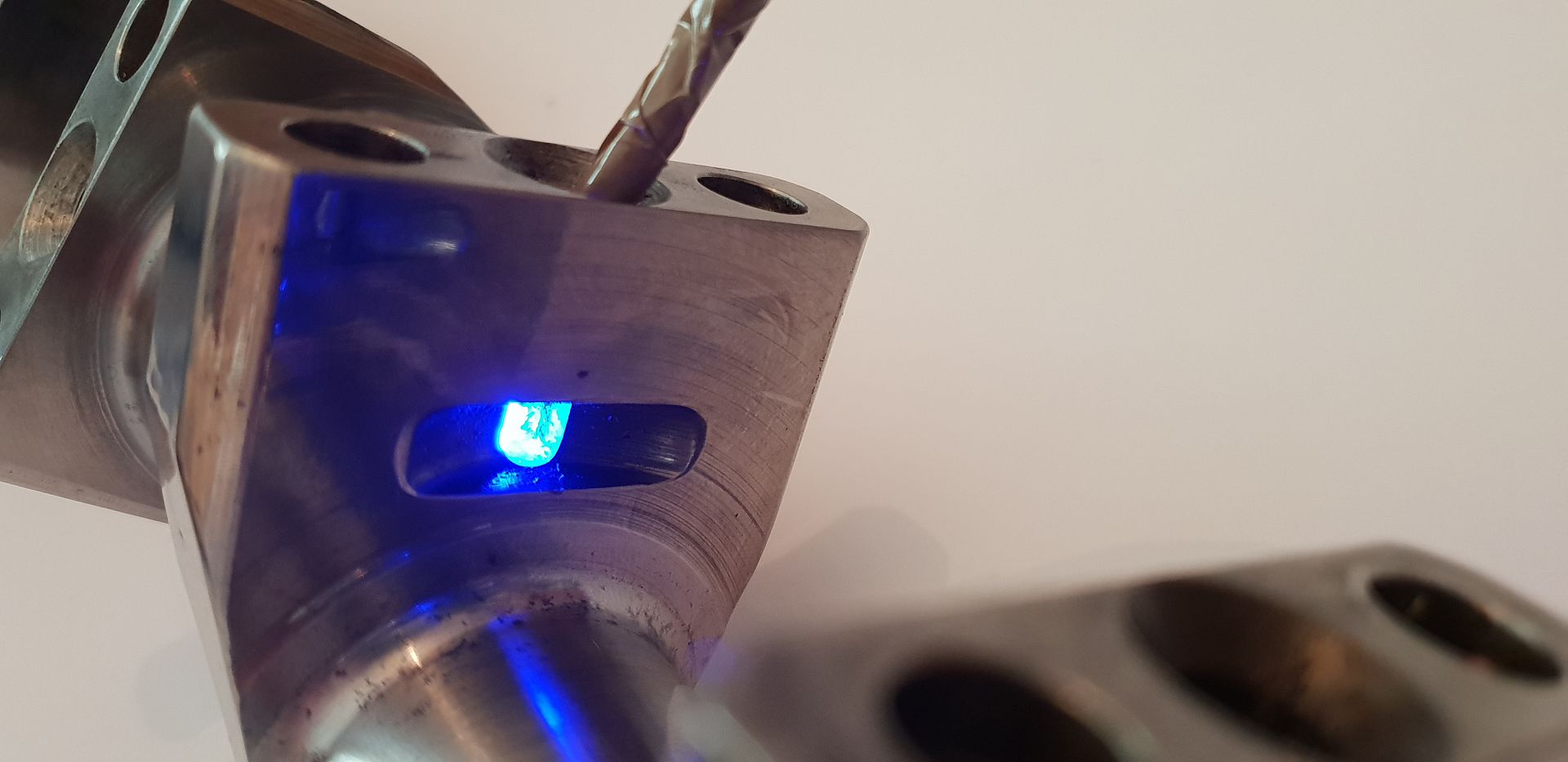
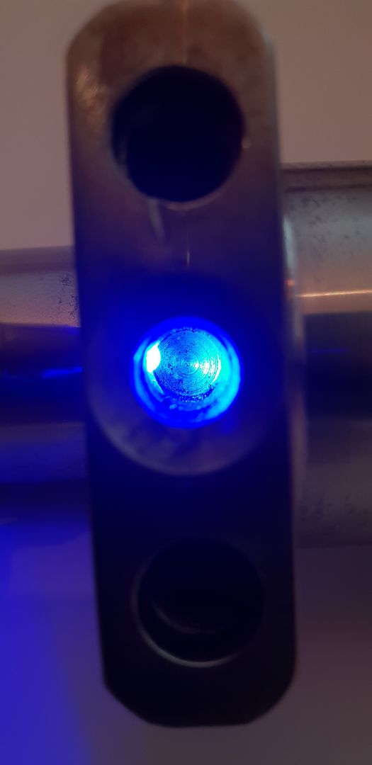
Shining an led into the first counter balance mass shows the small communal drilling from nose to provide cooling under the waisted plug, all the other counter balance masses rely on splash oil entering around the waisted plug to provide cooling.
Image

Image

As you can see the other drillings in the counter balance masses are just blind holes to accept waisted plugs,
Image

Image

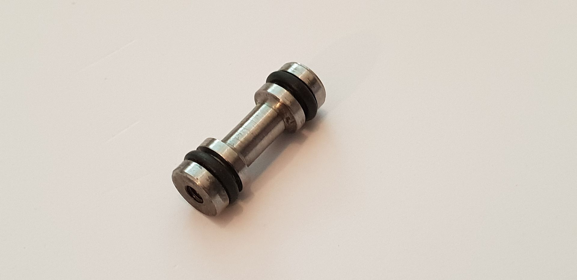
The plugs in question,

Image

Image

Image

Image

Image

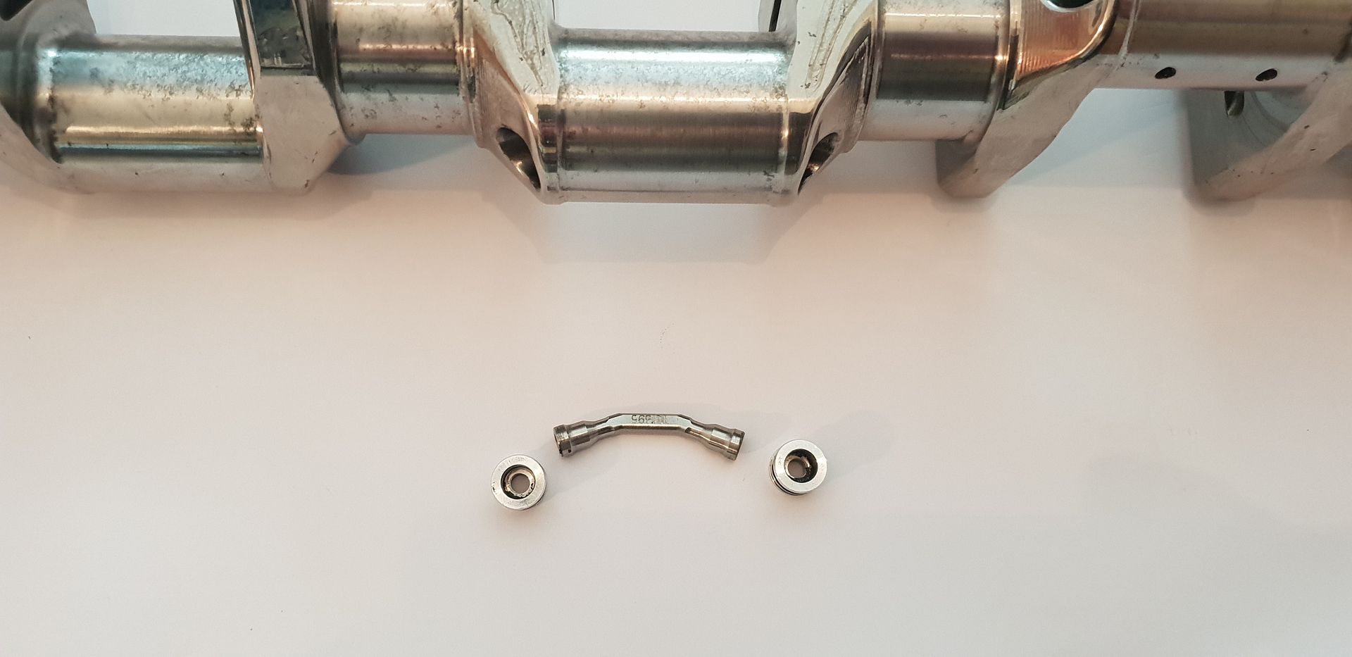
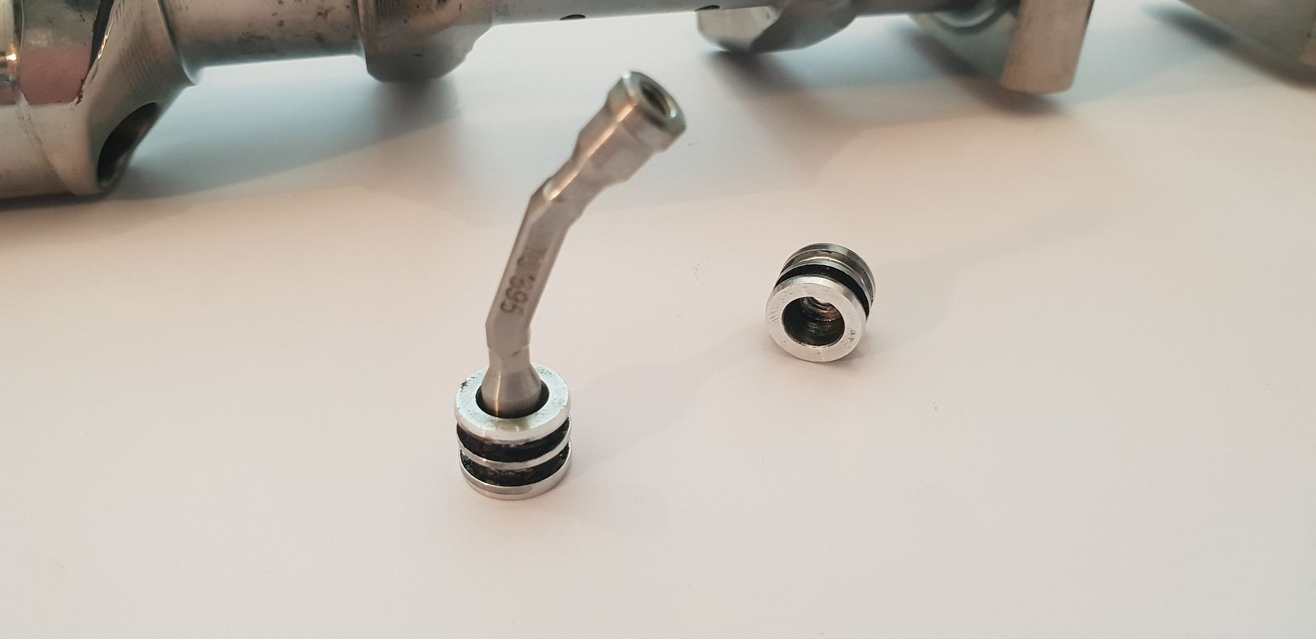
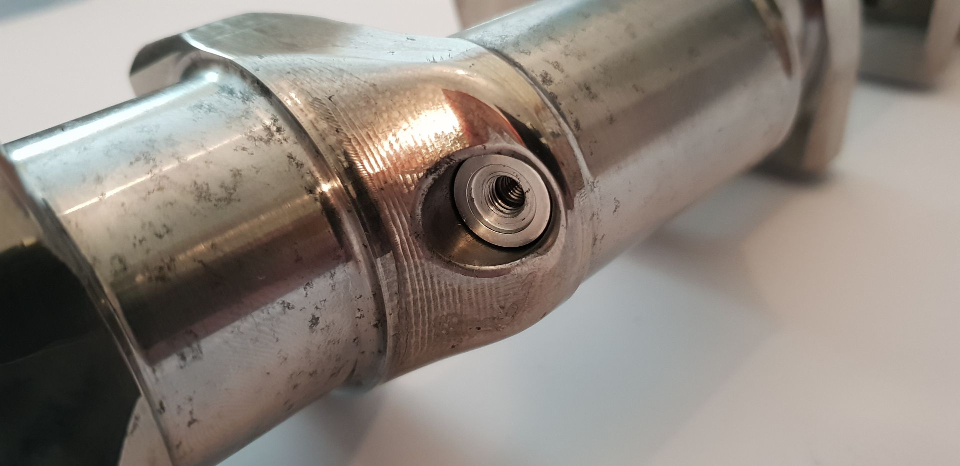
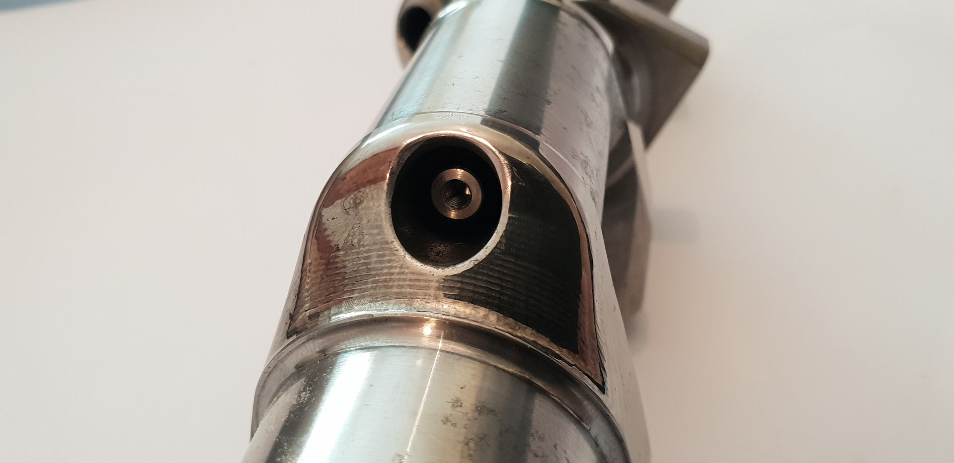
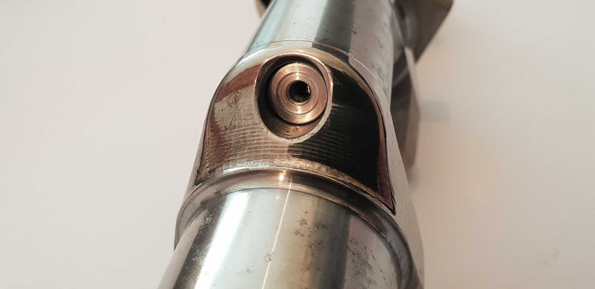
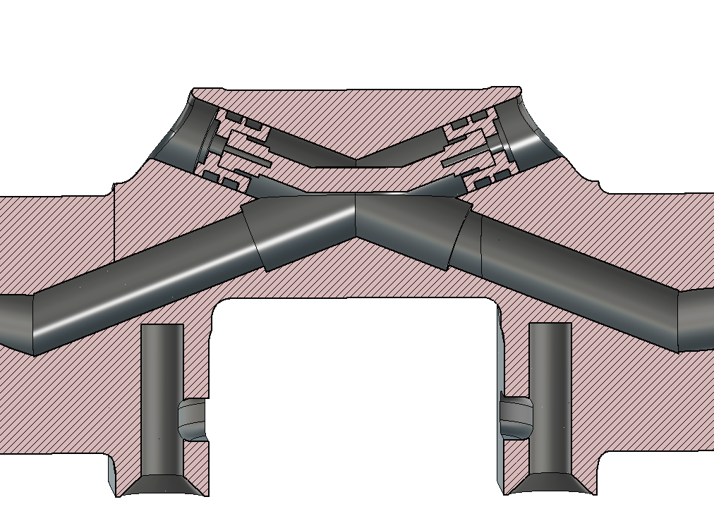
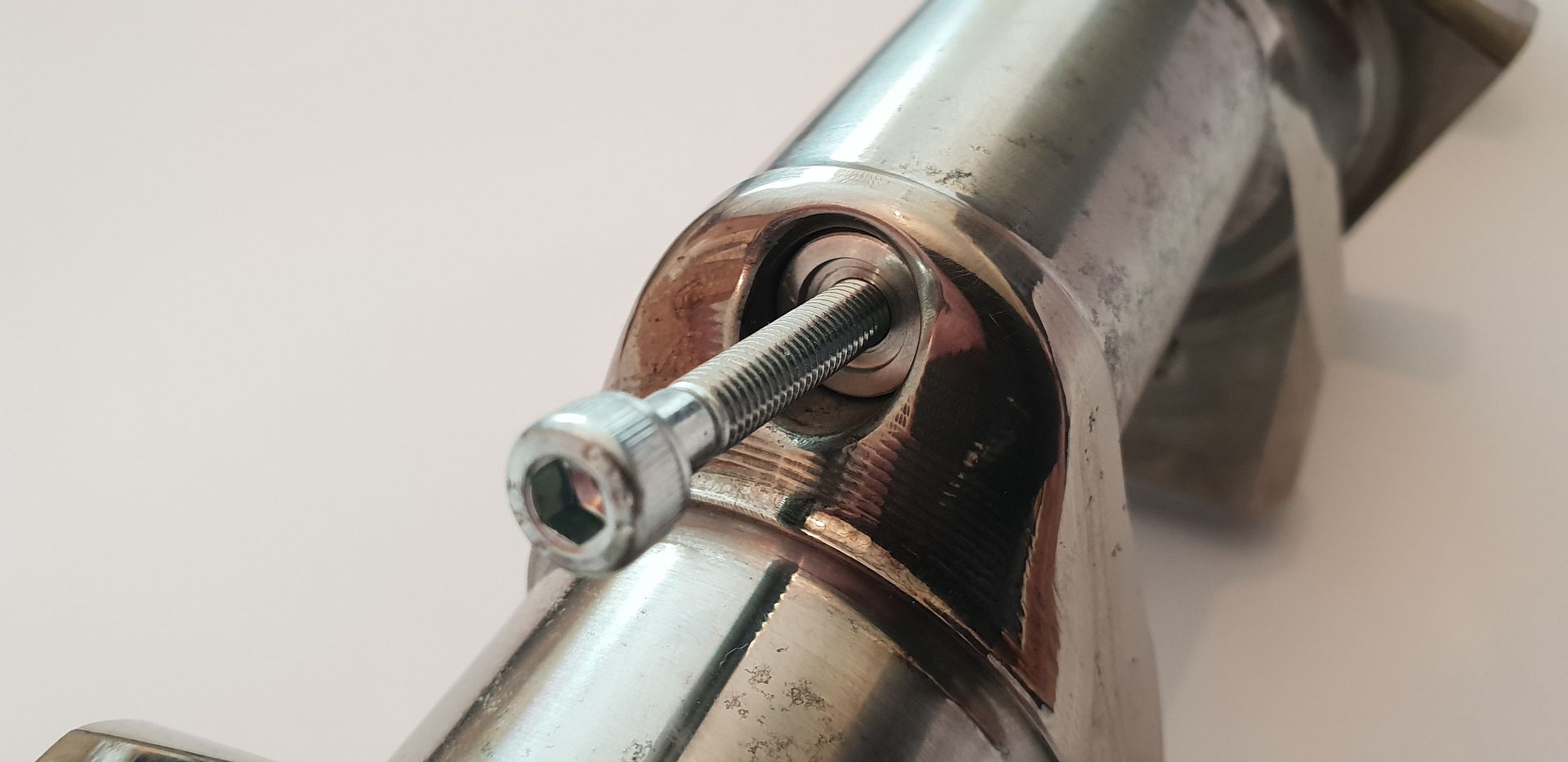
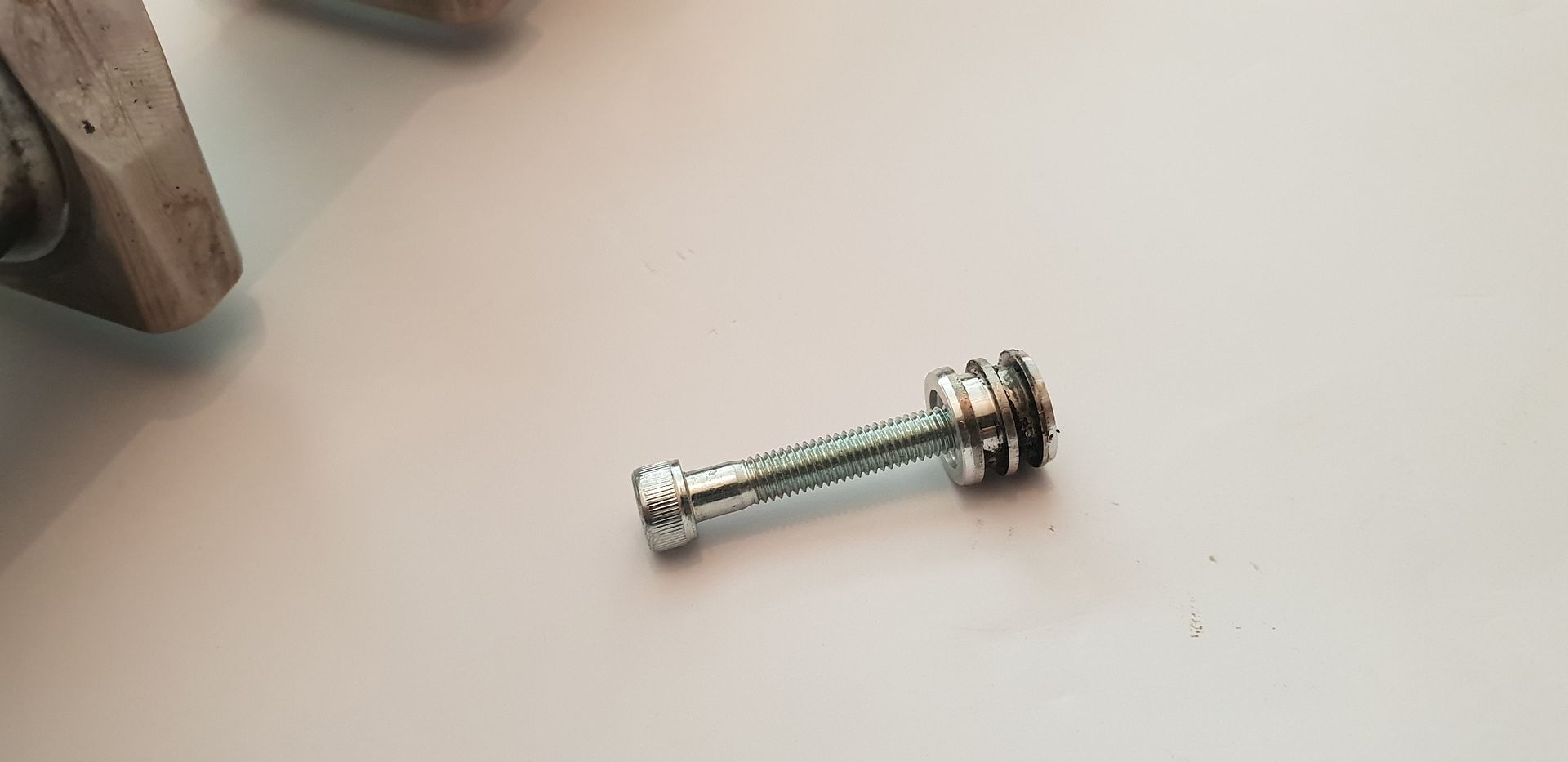
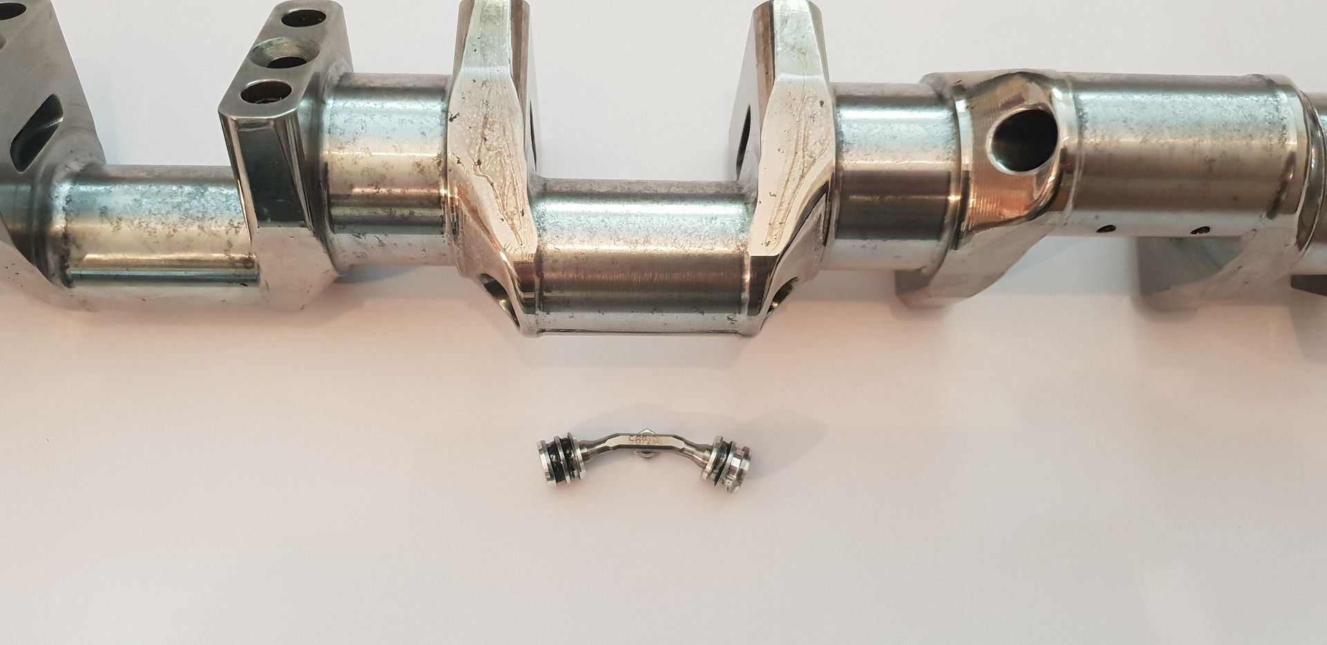
Because the main drillings need access for drilling in order for them all to connect to the supply at the nose the access drillings then need blanking in order to contain the oil pressure - this is done with two o-ringed aluminium bungs per web and are connected and locked in place internally with a titanium bridging brace as shown below(o-rings removed for ease of fitting),
Image

Image

The bungs and bridging brace shown below,
Image

Image

Image

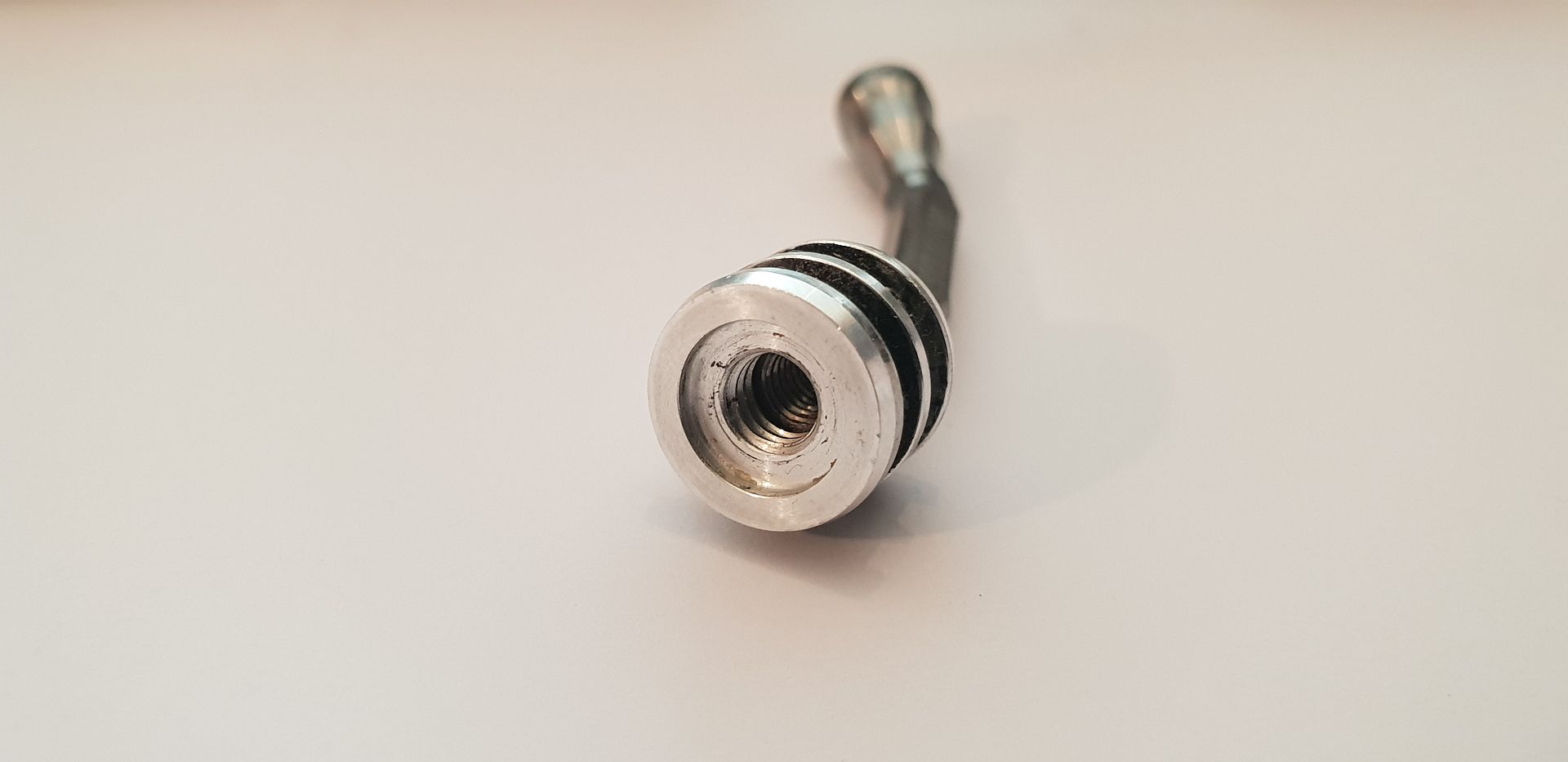
The bungs feature a larger thread than the bridge retaining bolt thread for ease of removal,
Image

Fitted one side,

Image

Bridge fitted,

Image

Second opposite bung fitted,

Image

Cross-section,

Image

Removal,

Image

Image

Image

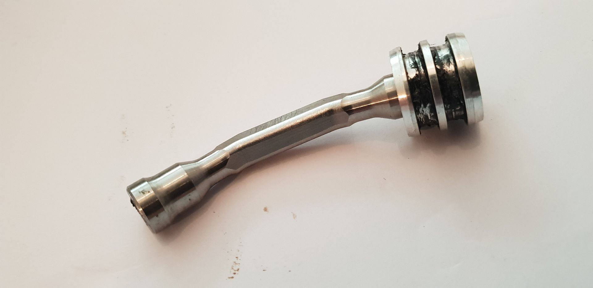
The bridge features a square cross-section in order to grip it on the bench with tightening the M4 holding the bung on one side first - once fitted inside crank, the second bung screw can be tightened as the crank stops the bridge assembly from turning,
Image

To finish, the big end journals are 33.98mm in diameter, the main journals are 41.98mm in diameter, the stroke is 42mm(+/-.1mm) and the journal angular offsets are as follows taking the timing gear end journal to be zero degrees, and following around in a clockwise direction as you view crank from gearbox end - counting journal numbers coming towards you,

Timing End Journal 1 - 0 Degrees
Journal 2 - 64 degrees
Journal 3 - 134 Degrees
Journal 4 - 209 Degrees
Journal 5 - 265.5 Degrees

I have not yet looked at the angular dimensions bar cading it, but I suspect there is some machined in twist so that the crank runs true under power. I'll make the above angle offset call-outs a bit clearer with some cad next week.

Hope that fills in a few unanswered questions in terms of F1 Crankshafts....

All the Best,

Brian,
If you think you cant, you wont, If you think you can, you will

User avatar
Chuckjr
38
Joined: Fri Feb 24, 2012 7:34 am
Location: USA

Re: F1 Crankshaft, a closer look

Post

Thank you Brian. Really enjoyed this read and pictures. Well done. Thank you for taking the time.
Watching F1 since 1986.

saviour stivala
saviour stivala
49
Joined: Wed Apr 25, 2018 11:54 am

Re: F1 Crankshaft, a closer look

Post

Fantastic incredible detail.

Martin Keene
Martin Keene
7
Joined: Tue May 11, 2010 8:02 am

Re: F1 Crankshaft, a closer look

Post

The counter weights have been removed because they were made of uranium on this engine...

Tommy Cookers
Tommy Cookers
638
Joined: Fri Feb 17, 2012 3:55 pm

Re: F1 Crankshaft, a closer look

Post

wouldn't a THA (Tungsten Heavy Alloy) be stronger and marginally denser than DU (Depleted Uranium) ?

you'd want a lot of strength at 20000 rpm but not much in inertial 'weights' changing oscillation frequencies in eg Boeing 747
and DU has been retroactively replaced by THAs in aircraft

saviour stivala
saviour stivala
49
Joined: Wed Apr 25, 2018 11:54 am

Re: F1 Crankshaft, a closer look

Post

Brain;- “the part bellow is from the Cosworth TJV10 engine” (19k max rpm). “its counterweights have also been removed but they are pretty inanimate objects in a way”. Assuming Brain acquired the crankshaft complete with counterweights and removed them himself he is the one that can shed light as to the actual material used for counterweighting.

User avatar
coaster
16
Joined: Sat Jun 30, 2012 4:10 am

Re: F1 Crankshaft, a closer look

Post

Uranium? Impossible, must be tungsten.
The f1 engine could not go for a world tour and get through customs with geiger meters going of the charts.
(Check your sources)

roy928tt
roy928tt
0
Joined: Tue Jul 11, 2017 11:55 am

Re: F1 Crankshaft, a closer look

Post

Ah, I think it might be right that they used Depleted Uranium, I seem to recall reading somewhere about a Cosworth engineer having to retrieve a lost counterweight from a racetrack (physically dig it out of the track surface after an engine failure). Companies get a bit nervous about losing uranium, depleted or not. The alloy of tungsten required for use as a counterweight is actually less dense than depleted uranium and I suspect that it will be found that depleted uranium just has better properties for the job at hand.

63l8qrrfy6
63l8qrrfy6
368
Joined: Wed Feb 17, 2016 8:36 pm

Re: F1 Crankshaft, a closer look

Post

All F1 engines I know of have used some form of sintered tungsten for crank balance weights. Densamet and another alloy I can't remember seemed to be the more common ones.

Great topic as usual Brian.
One thing I want to add is that the nose fitting functions as an oil centrifugal separator. I am fairly sure that what you have identified as a drilling for cooling the first balance mass is actually the air outlet from the middle of the fitting impeller.

Brian.G
Brian.G
334
Joined: Fri Dec 10, 2010 10:52 pm
Location: Ireland

Re: F1 Crankshaft, a closer look

Post

Mudflap wrote:
Fri May 31, 2019 1:06 pm
All F1 engines I know of have used some form of sintered tungsten for crank balance weights. Densamet and another alloy I can't remember seemed to be the more common ones.

Great topic as usual Brian.
One thing I want to add is that the nose fitting functions as an oil centrifugal separator. I am fairly sure that what you have identified as a drilling for cooling the first balance mass is actually the air outlet from the middle of the fitting impeller.
You are correct re air way I would imagine as it would collect there since it is less susceptible to G force. - I'm not sure how the air would actually escape past the vertical o-ringed plugs however but perhaps it would push past the lower o-ring.

Brian,
If you think you cant, you wont, If you think you can, you will

63l8qrrfy6
63l8qrrfy6
368
Joined: Wed Feb 17, 2016 8:36 pm

Re: F1 Crankshaft, a closer look

Post

I was revisiting this thread and realized that the pocket on the web cheek, below the big end fillet is a stress relieving feature. Its purpose is to de-stiffen the pin fillet along the critical diagonal (the imaginary line joining the bottom of the pin fillet to the top of the main journal fillet).

These features were named after a German bloke who experimented with such shapes way before my time - I'll try to find some references over the weekend and maybe show how it works.

63l8qrrfy6
63l8qrrfy6
368
Joined: Wed Feb 17, 2016 8:36 pm

Re: F1 Crankshaft, a closer look

Post

So it appears that the relief feature below the crank pin dates back to the 1912 Sulzer locomotive engine and it is sometimes referred to as a Klose relief (see Adolf Klose).

Variations of this stress relief groove have been commonplace in F1. This particular shape shown by Brian has been carried over to the Cosworth CA engine (where it no longer broke through to the counterweight thread bores).

The disadvantage is that it decreases the overall crankshaft bending stiffness which promotes big end bearing edge loading. Crankshaft pins are profiled axially (barreled) to counter this.

It is also worth noting that on a conventional crankshaft (as opposed to nose oil fed) a similar stress reduction effect can be achieved by boring through the main journal.

Below is a similar feature on the Honda V8 crankshaft.

Image


Here I've had a go at sketching a crank segment to quantify how effective such a groove would be. The Cosworth type relief reduced the pin fillet stress by 6.5% right away - with a bit of tweaking I am sure the effect can be doubled.

I've used Honda V8 stroke, bore pitch and journal diameters to mock up a crank.

Image

User avatar
PlatinumZealot
558
Joined: Thu Jun 12, 2008 2:45 am

Re: F1 Crankshaft, a closer look

Post

Yup internal forces tend to travel thru the stiffest route. So by creating that slot to "divert" the stiffness you get reduced stress in targeted areas. But as you said, care must be taken.
🖐️✌️☝️👀👌✍️🐎🏆🙏

Racing Green in 2028

Brian.G
Brian.G
334
Joined: Fri Dec 10, 2010 10:52 pm
Location: Ireland

Re: F1 Crankshaft, a closer look

Post

Great info and delighted it sparked further conversation.

Brian,
If you think you cant, you wont, If you think you can, you will

coseng
coseng
0
Joined: Tue Dec 10, 2019 1:29 am
Location: Jersey City, NJ

Re: F1 Crankshaft, a closer look

Post

Brian,

Thanks for this post. It was very helpful for me in thinking of ways to oil my single cylinder roadracer crank. I put a post up at viewtopic.php?f=14&t=28652 if you have any time to take a peek and chime in. Same goes for anyone else wanting to venture an opinion.

Thanks,
Chris
Cosentino Engineering
www.cosentinoengineering.com