2022 Aerodynamic Regulations Thread

Here are our CFD links and discussions about aerodynamics, suspension, driver safety and tyres. Please stick to F1 on this forum.
User avatar
jjn9128
769
Joined: 02 May 2017, 23:53

Re: 2022 Aero Thread

Post

Floor edge flexibility is already subject to a load test.
3.15.5 Front Floor Flexibility
Bodywork flexibility will be tested by applying a load vertically upwards using a 50mm diameter pad with a gimbled interface to the loadcell. The position of the centre of the pad will be given by the FIA and will be on the underside of the plank within a quadrilateral area with vertices at points [XF=460, 50], [XF=610, 65], [XF=610, -65], [XF=460, -50]. The deflection will be measured along the loading axis.

At all times during the test, the load at a given deflection must exceed the load given by a straight-line graph defined by connecting the following coordinates in order: (0 mm, 0 N) (1 mm, 0 N) (5 mm, 4000N) (25mm, 6000N). This must be the case whether the deflection is increasing, decreasing, or held constant. The test will have no more than a maximum load of 8000N or a maximum deflection of 15mm (whichever is reached first) unless specifically requested by the FIA to investigate behaviour above these limits.

The load deflection relationship must be strictly monotonic with both increasing and decreasing deflection.


3.15.6 Outboard Floor Flexibility
a. Bodywork may deflect no more than 8mm vertically when a [0, 0, -500]N load is applied to it at [XR=-450, ±450, 155]. The load will be applied using a 50mm diameter ram and an adaptor of the same size. Teams must supply the latter when such a test is deemed necessary.

b. Bodywork may deflect no more than 3mm vertically when a [0, 0, -100]N load is applied to it at [XR=-450, ±600, 60]. The load will be applied using a 50mm diameter ram and an adaptor of the same size. Teams must supply the latter when such a test is deemed necessary.
#aerogandalf
"There is one big friend. It is downforce. And once you have this it’s a big mate and it’s helping a lot." Robert Kubica

User avatar
godlameroso
309
Joined: 16 Jan 2010, 21:27
Location: Miami FL

Re: 2022 Aero Thread

Post

8mm is 1/3 of an inch, while not a huge amount it is not insignificant.
Saishū kōnā

User avatar
dans79
267
Joined: 03 Mar 2013, 19:33
Location: USA

Re: 2022 Aero Thread

Post

godlameroso wrote:
10 Nov 2021, 20:14
8mm is 1/3 of an inch, while not a huge amount it is not insignificant.

Thats this years rules, next years are more stringent.

https://www.fia.com/sites/default/files ... -10-15.pdf

3.15.6 Front Floor Flexibility
Bodywork flexibility will be tested by applying a load vertically upwards using a 50mm
diameter pad with a gimbled interface to the loadcell. The position of the centre of the pad
will be given by the FIA and will be on the underside of the plank within a quadrilateral area,
with vertices at points [XF=460, 50], [XF=610, 65], [XF=610, -65], [XF=460, -50]. The deflection
will be measured along the loading axis.

At all times during the test, the load at a given deflection must exceed the load given by a
straight-line graph defined by connecting the following coordinates in order: (0 mm, 0 N) (1
mm, 0 N) (5 mm, 4000N) (25mm, 6000N). This must be the case whether the deflection is
increasing, decreasing, or held constant. The test will have no more than a maximum load of
8000N or a maximum deflection of 15mm (whichever is reached first) unless specifically
requested by the FIA to investigate behaviour above these limits.

The load deflection relationship must be strictly monotonic with both increasing and
decreasing deflection.
3.15.7 Outboard Floor Flexibility
a. Bodywork may deflect no more than 5mm vertically when a [0, 0, -500]N load is
applied to it at XR=-450 and Y= ±450. The load will be applied using a 50mm diameter
ram and an adaptor of the same size. Teams must supply the latter when such a test is
deemed necessary.

b. Bodywork may deflect no more than 20mm vertically when a [0, 0, 500]N load is
applied to it at points [XR, Y] [-450, ±600] or [-1300, ±670]. The load will be applied
using a 50mm diameter ram and an adaptor of the same size in an upwards or
downwards direction. Teams must supply the latter when such a test is deemed
necessary
3.15.8 Central Floor Flexibility
a. Bodywork within RV-PLANK may deflect no more than 1mm at the two holes in the
plank at XF=1080 and no more than 2mm at the rearmost hole, when the car, without
driver, is supported at these positions. The car will be supported on 70mm diameter
pads, centred on the holes, and only in contact with the underside of the plank
assembly. The displacement will be measured at the supports, relative to the
reference plane at the centre of each hole. Furthermore, there may be up to 1mm
additional deflection at the forward positions provided it complies with Article 3.15.2.

b. Bodywork on the reference plane may deflect no more than 0.2mm when the car,
without driver, is supported at the two holes in the plank at XF=1080 and at the
rearmost hole in the plank. The car will be supported on 40mm diameter pads,
centred on the holes, and only contacting the bodywork on the reference plane. For
the two holes at XF=1080 the displacement will be measured at the supports, relative
to the survival cell datum points detailed in Article 3.2.6. For the rearmost hole the
displacement will be measured at the support, relative to the power unit at the
uppermost transmission mounting studs detailed in Article 5.4.8.

Also if a floor flexed anywhere close to as much as the rules allowed, the car would be next to impossible to drive. The flutter it would have would lead to a lot of downforce instability, as you would run the risk of stalling the floor.
197 104 103 7

User avatar
godlameroso
309
Joined: 16 Jan 2010, 21:27
Location: Miami FL

Re: 2022 Aero Thread

Post

Image

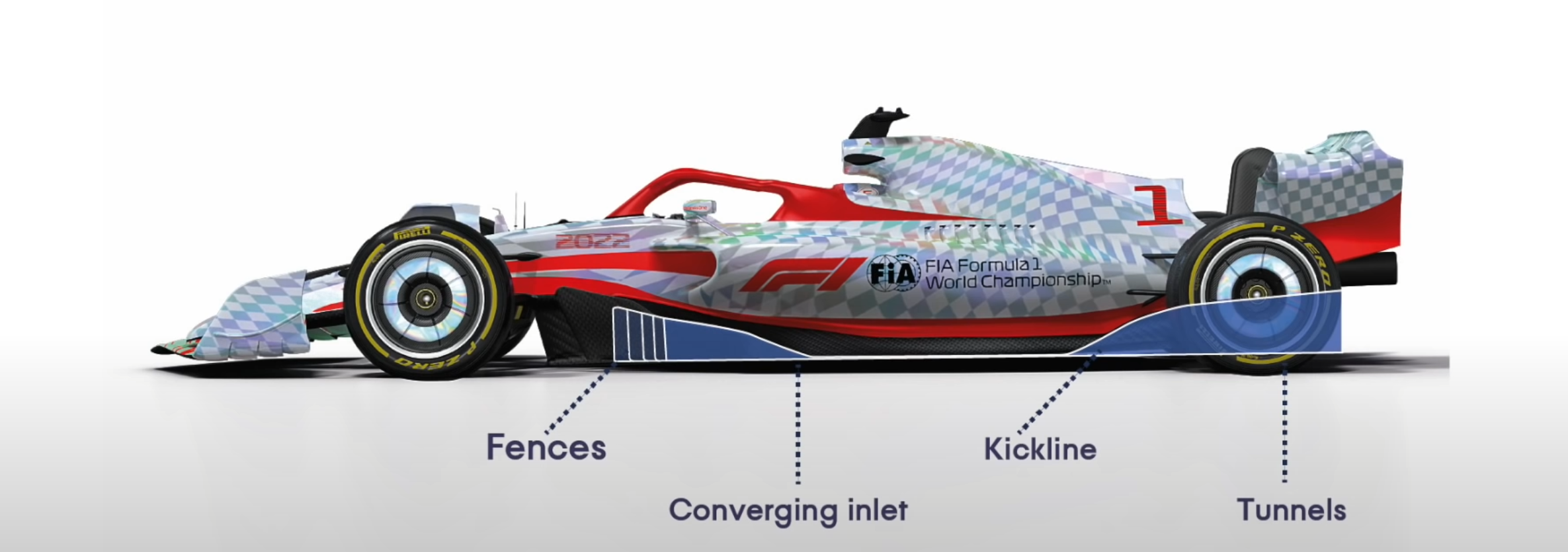
It's starting to become clear what is possible with the new floors. The front fences will be critical to accelerate the airflow into the tunnels. If the central section of the tunnel before the diffuser is that close to the road it's very likely we could have local supersonic flow at the converging inlet and kink line of the diffuser. Choking and blocking will come into play, so ensuring sufficient mass flow at the inlet will be crucial for floor performance.

Since part of the diffuser tunnel is made by the road, the shape of the road will have a big influence on diffuser performance.

Therefore, the inlet fences should work as part vortex generators, and also create a large stagnation pressure outboard of the inlets. This will coax the maximum amount of airflow into the floor. Getting the inlet fences correct will have a big influence in how much rake angle can be ran, which can lead to lower ride height sensitivity for the diffuser.

If you only have SS flow at the inlet but not the diffuser kick line the floor will work much worse than having SS flow at both inlet and diffuser kick.
Saishū kōnā

Just_a_fan
591
Joined: 31 Jan 2010, 20:37

Re: 2022 Aero Thread

Post

godlameroso wrote:
11 Nov 2021, 16:48
https://files.catbox.moe/ysr3vl.png

It's starting to become clear what is possible with the new floors. The front fences will be critical to accelerate the airflow into the tunnels. If the central section of the tunnel before the diffuser is that close to the road it's very likely we could have local supersonic flow at the converging inlet and kink line of the diffuser. Choking and blocking will come into play, so ensuring sufficient mass flow at the inlet will be crucial for floor performance.

Since part of the diffuser tunnel is made by the road, the shape of the road will have a big influence on diffuser performance.

Therefore, the inlet fences should work as part vortex generators, and also create a large stagnation pressure outboard of the inlets. This will coax the maximum amount of airflow into the floor. Getting the inlet fences correct will have a big influence in how much rake angle can be ran, which can lead to lower ride height sensitivity for the diffuser.

If you only have SS flow at the inlet but not the diffuser kick line the floor will work much worse than having SS flow at both inlet and diffuser kick.
Supersonic flow under the car? How fast do you think these cars are going to go? :shock:
If you are more fortunate than others, build a larger table not a taller fence.

User avatar
godlameroso
309
Joined: 16 Jan 2010, 21:27
Location: Miami FL

Re: 2022 Aero Thread

Post

Just_a_fan wrote:
11 Nov 2021, 17:18
godlameroso wrote:
11 Nov 2021, 16:48
https://files.catbox.moe/ysr3vl.png

It's starting to become clear what is possible with the new floors. The front fences will be critical to accelerate the airflow into the tunnels. If the central section of the tunnel before the diffuser is that close to the road it's very likely we could have local supersonic flow at the converging inlet and kink line of the diffuser. Choking and blocking will come into play, so ensuring sufficient mass flow at the inlet will be crucial for floor performance.

Since part of the diffuser tunnel is made by the road, the shape of the road will have a big influence on diffuser performance.

Therefore, the inlet fences should work as part vortex generators, and also create a large stagnation pressure outboard of the inlets. This will coax the maximum amount of airflow into the floor. Getting the inlet fences correct will have a big influence in how much rake angle can be ran, which can lead to lower ride height sensitivity for the diffuser.

If you only have SS flow at the inlet but not the diffuser kick line the floor will work much worse than having SS flow at both inlet and diffuser kick.
Supersonic flow under the car? How fast do you think these cars are going to go? :shock:
Local supersonic flow, at the lowest pressure point. It's not hard to have plus 1 mach numbers at a very isolated section while the bulk flow itself is subsonic. The mantis shrimp doesn't make the whole ocean go hypersonic, just a very small part of it. Likewise the diffuser doesn't make all the airflow underneath it supersonic, just a very small part of it. That very small part can be choked upstream, and when the flow is choked, the supersonic flow at the throat extends into the diffuser.

As long as upstream mass flow is sufficient you can have a choked diffuser. That's always been the name of the game, and RBR is just better at it. Next year this knowledge and understanding is just shaped differently. Same rules of nature still apply.


Everything I say is inline with the information in this video. And this guy has that 50's science voice so you know it's legit. We make local supersonic flows in the same limited narrow window we make smooth laminar flow, the bulk of it is sub sonic just as it is turbulent in overall scope.
Saishū kōnā

User avatar
theVortexCreatorY250
12
Joined: 07 Oct 2021, 14:53

Re: 2022 Aero Thread

Post

godlameroso wrote:
11 Nov 2021, 16:48
https://files.catbox.moe/ysr3vl.png

It's starting to become clear what is possible with the new floors. The front fences will be critical to accelerate the airflow into the tunnels. If the central section of the tunnel before the diffuser is that close to the road it's very likely we could have local supersonic flow at the converging inlet and kink line of the diffuser. Choking and blocking will come into play, so ensuring sufficient mass flow at the inlet will be crucial for floor performance.

Since part of the diffuser tunnel is made by the road, the shape of the road will have a big influence on diffuser performance.

Therefore, the inlet fences should work as part vortex generators, and also create a large stagnation pressure outboard of the inlets. This will coax the maximum amount of airflow into the floor. Getting the inlet fences correct will have a big influence in how much rake angle can be ran, which can lead to lower ride height sensitivity for the diffuser.

If you only have SS flow at the inlet but not the diffuser kick line the floor will work much worse than having SS flow at both inlet and diffuser kick.
To be honest I can't see the SS effects being much larger that they are today, although yes at 350km/h compressibility will exist. Why do you say that a large CpT (stagnation) OB of the fences allows more air to come into the floor? If anything more outwash in that region pushes air away from the floor- yes increasing floor peformance then sucking it back in however I sitll don't know what you mean.

I think maximising the floor inlet (should be easy) and position of the fences relative to the body is key. Between the fence and the body a large low Cp is generated as both surfaces expand.
I create vortices

Just_a_fan
591
Joined: 31 Jan 2010, 20:37

Re: 2022 Aero Thread

Post

godlameroso wrote:
11 Nov 2021, 17:37
Just_a_fan wrote:
11 Nov 2021, 17:18
godlameroso wrote:
11 Nov 2021, 16:48
https://files.catbox.moe/ysr3vl.png

It's starting to become clear what is possible with the new floors. The front fences will be critical to accelerate the airflow into the tunnels. If the central section of the tunnel before the diffuser is that close to the road it's very likely we could have local supersonic flow at the converging inlet and kink line of the diffuser. Choking and blocking will come into play, so ensuring sufficient mass flow at the inlet will be crucial for floor performance.

Since part of the diffuser tunnel is made by the road, the shape of the road will have a big influence on diffuser performance.

Therefore, the inlet fences should work as part vortex generators, and also create a large stagnation pressure outboard of the inlets. This will coax the maximum amount of airflow into the floor. Getting the inlet fences correct will have a big influence in how much rake angle can be ran, which can lead to lower ride height sensitivity for the diffuser.

If you only have SS flow at the inlet but not the diffuser kick line the floor will work much worse than having SS flow at both inlet and diffuser kick.
Supersonic flow under the car? How fast do you think these cars are going to go? :shock:
Local supersonic flow, at the lowest pressure point. It's not hard to have plus 1 mach numbers at a very isolated section while the bulk flow itself is subsonic. The mantis shrimp doesn't make the whole ocean go hypersonic, just a very small part of it. Likewise the diffuser doesn't make all the airflow underneath it supersonic, just a very small part of it. That very small part can be choked upstream, and when the flow is choked, the supersonic flow at the throat extends into the diffuser.

As long as upstream mass flow is sufficient you can have a choked diffuser. That's always been the name of the game, and RBR is just better at it. Next year this knowledge and understanding is just shaped differently. Same rules of nature still apply.


Everything I say is inline with the information in this video. And this guy has that 50's science voice so you know it's legit. We make local supersonic flows in the same limited narrow window we make smooth laminar flow, the bulk of it is sub sonic just as it is turbulent in overall scope.
The Mantis Shrimp doesn't go at supersonic speeds either. The claws move at about 50mph. But they cause a cavitation bubble and it is the collapse of the bubble that does the damage because, as it collapses, it forms a narrow jet of water than hits the surface of the prey at high speed and breaks the shell.

But how are you going to get supersonic flow at any point under the car? The demonstration video, whilst very interesting, is using a vacuum pump to drag air through the system. I'm doubtful that an F1 car will manage anything similar.
If you are more fortunate than others, build a larger table not a taller fence.

Tommy Cookers
617
Joined: 17 Feb 2012, 16:55

Re: 2022 Aero Thread

Post

godlameroso wrote:
11 Nov 2021, 17:37
Local supersonic flow, at the lowest pressure point etc....
afaik
(super)sonic relative velocity isn't the same thing as (super)sonic flow
(super)sonic flow means real (super)sonic velocity not relative (super)sonic velocity

a body moving near-sonically through stillish air causes the relative velocity of the air to be sonic

a body moving relatively slowly through stillish air can't cause the relative velocity of the air to be sonic
because it can't accelerate the air to the near-sonic velocity needed to reach a sonic relative velocity

so 'local supersonic flow' doesn't happen in F1
(the necessary air will always find another route around the moving body)
ie there's no big force to accelerate the air to near-sonic velocity

User avatar
godlameroso
309
Joined: 16 Jan 2010, 21:27
Location: Miami FL

Re: 2022 Aero Thread

Post

Just_a_fan wrote:
11 Nov 2021, 19:10
godlameroso wrote:
11 Nov 2021, 17:37
Just_a_fan wrote:
11 Nov 2021, 17:18


Supersonic flow under the car? How fast do you think these cars are going to go? :shock:
Local supersonic flow, at the lowest pressure point. It's not hard to have plus 1 mach numbers at a very isolated section while the bulk flow itself is subsonic. The mantis shrimp doesn't make the whole ocean go hypersonic, just a very small part of it. Likewise the diffuser doesn't make all the airflow underneath it supersonic, just a very small part of it. That very small part can be choked upstream, and when the flow is choked, the supersonic flow at the throat extends into the diffuser.

As long as upstream mass flow is sufficient you can have a choked diffuser. That's always been the name of the game, and RBR is just better at it. Next year this knowledge and understanding is just shaped differently. Same rules of nature still apply.


Everything I say is inline with the information in this video. And this guy has that 50's science voice so you know it's legit. We make local supersonic flows in the same limited narrow window we make smooth laminar flow, the bulk of it is sub sonic just as it is turbulent in overall scope.
The Mantis Shrimp doesn't go at supersonic speeds either. The claws move at about 50mph. But they cause a cavitation bubble and it is the collapse of the bubble that does the damage because, as it collapses, it forms a narrow jet of water than hits the surface of the prey at high speed and breaks the shell.

But how are you going to get supersonic flow at any point under the car? The demonstration video, whilst very interesting, is using a vacuum pump to drag air through the system. I'm doubtful that an F1 car will manage anything similar.
The car moving is dragging air through the system ain't it?
Saishū kōnā

User avatar
godlameroso
309
Joined: 16 Jan 2010, 21:27
Location: Miami FL

Re: 2022 Aero Thread

Post

theVortexCreatorY250 wrote:
11 Nov 2021, 18:36
godlameroso wrote:
11 Nov 2021, 16:48
https://files.catbox.moe/ysr3vl.png

It's starting to become clear what is possible with the new floors. The front fences will be critical to accelerate the airflow into the tunnels. If the central section of the tunnel before the diffuser is that close to the road it's very likely we could have local supersonic flow at the converging inlet and kink line of the diffuser. Choking and blocking will come into play, so ensuring sufficient mass flow at the inlet will be crucial for floor performance.

Since part of the diffuser tunnel is made by the road, the shape of the road will have a big influence on diffuser performance.

Therefore, the inlet fences should work as part vortex generators, and also create a large stagnation pressure outboard of the inlets. This will coax the maximum amount of airflow into the floor. Getting the inlet fences correct will have a big influence in how much rake angle can be ran, which can lead to lower ride height sensitivity for the diffuser.

If you only have SS flow at the inlet but not the diffuser kick line the floor will work much worse than having SS flow at both inlet and diffuser kick.
To be honest I can't see the SS effects being much larger that they are today, although yes at 350km/h compressibility will exist. Why do you say that a large CpT (stagnation) OB of the fences allows more air to come into the floor? If anything more outwash in that region pushes air away from the floor- yes increasing floor peformance then sucking it back in however I sitll don't know what you mean.

I think maximising the floor inlet (should be easy) and position of the fences relative to the body is key. Between the fence and the body a large low Cp is generated as both surfaces expand.
Think of stagnation pressure as a column if you have fluid travelling perpendicular to the column the fluid will go around the column. Creating static, or even above static pressure on the outboard of the fences not only creates a pressure differential which will create a down force by itself, but also act as a wall, and since the floor inlet will be at a lower pressure, air will want to go in that direction. Rather than force its way outboard of the fences. It's how the bargeboards work today.
Saishū kōnā

User avatar
godlameroso
309
Joined: 16 Jan 2010, 21:27
Location: Miami FL

Re: 2022 Aero Thread

Post

Tommy Cookers wrote:
11 Nov 2021, 19:27
godlameroso wrote:
11 Nov 2021, 17:37
Local supersonic flow, at the lowest pressure point etc....
afaik
(super)sonic relative velocity isn't the same thing as (super)sonic flow
(super)sonic flow means real (super)sonic velocity not relative (super)sonic velocity

a body moving near-sonically through stillish air causes the relative velocity of the air to be sonic

a body moving relatively slowly through stillish air can't cause the relative velocity of the air to be sonic
because it can't accelerate the air to the near-sonic velocity needed to reach a sonic relative velocity

so 'local supersonic flow' doesn't happen in F1
(the necessary air will always find another route around the moving body)
ie there's no big force to accelerate the air to near-sonic velocity
Thanks for clarifying. While the car is moving there is always an upstream and downstream flow, the way the car cuts through the air, and the air seeking equilibrium as a result is the big force that accelerates the air. The separation of positive(yang) and negative pressure(yin), creates force as a result of the static air surrounding that parcel of air moving across the car.
Saishū kōnā

Just_a_fan
591
Joined: 31 Jan 2010, 20:37

Re: 2022 Aero Thread

Post

godlameroso wrote:
11 Nov 2021, 20:29
Just_a_fan wrote:
11 Nov 2021, 19:10
godlameroso wrote:
11 Nov 2021, 17:37


Local supersonic flow, at the lowest pressure point. It's not hard to have plus 1 mach numbers at a very isolated section while the bulk flow itself is subsonic. The mantis shrimp doesn't make the whole ocean go hypersonic, just a very small part of it. Likewise the diffuser doesn't make all the airflow underneath it supersonic, just a very small part of it. That very small part can be choked upstream, and when the flow is choked, the supersonic flow at the throat extends into the diffuser.

As long as upstream mass flow is sufficient you can have a choked diffuser. That's always been the name of the game, and RBR is just better at it. Next year this knowledge and understanding is just shaped differently. Same rules of nature still apply.


Everything I say is inline with the information in this video. And this guy has that 50's science voice so you know it's legit. We make local supersonic flows in the same limited narrow window we make smooth laminar flow, the bulk of it is sub sonic just as it is turbulent in overall scope.
The Mantis Shrimp doesn't go at supersonic speeds either. The claws move at about 50mph. But they cause a cavitation bubble and it is the collapse of the bubble that does the damage because, as it collapses, it forms a narrow jet of water than hits the surface of the prey at high speed and breaks the shell.

But how are you going to get supersonic flow at any point under the car? The demonstration video, whilst very interesting, is using a vacuum pump to drag air through the system. I'm doubtful that an F1 car will manage anything similar.
The car moving is dragging air through the system ain't it?
Not in the way that the big vacuum pump is, no.
If you are more fortunate than others, build a larger table not a taller fence.

User avatar
godlameroso
309
Joined: 16 Jan 2010, 21:27
Location: Miami FL

Re: 2022 Aero Thread

Post

Just_a_fan wrote:
11 Nov 2021, 21:36
godlameroso wrote:
11 Nov 2021, 20:29
Just_a_fan wrote:
11 Nov 2021, 19:10

The Mantis Shrimp doesn't go at supersonic speeds either. The claws move at about 50mph. But they cause a cavitation bubble and it is the collapse of the bubble that does the damage because, as it collapses, it forms a narrow jet of water than hits the surface of the prey at high speed and breaks the shell.

But how are you going to get supersonic flow at any point under the car? The demonstration video, whilst very interesting, is using a vacuum pump to drag air through the system. I'm doubtful that an F1 car will manage anything similar.
The car moving is dragging air through the system ain't it?
Not in the way that the big vacuum pump is, no.
Well then what is the point of even having a wind tunnel in your F1 team? It's not the same as a car moving across a track, no matter how good your rolling road, and your algorithms compensate for wall effects. What's the point of using a simulator since it's not the way that driving a circuit is, it's just a simulation. Why use CFD if it's not visualizing the processes exactly as they are? Why use a dyno if it's not the same as running it in the car?

In the wind tunnel the car is stationary and the air is moving, it's not the same as on track, on track the air is moving and the car is moving, but teams still spend $30,000-50,000/hr doing wind tunnel runs. The reason is obviously because there is some correlation between a car running on track, and air being blown through the automotive windbag.
Saishū kōnā

Just_a_fan
591
Joined: 31 Jan 2010, 20:37

Re: 2022 Aero Thread

Post

godlameroso wrote:
11 Nov 2021, 22:59
Just_a_fan wrote:
11 Nov 2021, 21:36
godlameroso wrote:
11 Nov 2021, 20:29


The car moving is dragging air through the system ain't it?
Not in the way that the big vacuum pump is, no.
Well then what is the point of even having a wind tunnel in your F1 team? It's not the same as a car moving across a track, no matter how good your rolling road, and your algorithms compensate for wall effects. What's the point of using a simulator since it's not the way that driving a circuit is, it's just a simulation. Why use CFD if it's not visualizing the processes exactly as they are? Why use a dyno if it's not the same as running it in the car?

In the wind tunnel the car is stationary and the air is moving, it's not the same as on track, on track the air is moving and the car is moving, but teams still spend $30,000-50,000/hr doing wind tunnel runs. The reason is obviously because there is some correlation between a car running on track, and air being blown through the automotive windbag.
Rolling road. There, you got it. The wind tunnel attempts to replicate the track by having the air and the floor moving at the same speed as each other and relative to the model that isn't moving - this is the same as having the car moving through air that is not moving relative to the road surface. Your video blew air through a construction where the floor and the nozzle surface were still relative to each other. Only the air moved. Thus it's not like a car on a track.

The lack of a moving ground is key.
If you are more fortunate than others, build a larger table not a taller fence.

Post Reply