In this thread I will be unlocking a few secrets hidden within this part - The F1 Steering Rack and Control Valve, mainly its construction, operation, and some other features.
Before we begin I must give a quick shout out to Craig Scarborough @ScarbsTech. As you can imagine coming up with these posts takes a lot of looking online for interesting F1 parts. Spotted this part on Race to the Finish F1 parts website but being an Engine person couldn't identify what part of the car it was from. A message to Craig set things straight that it was steering related.
First off, a quick rundown on power steering and how it works. While this is basic to start off, it may be no harm read it all the same since sometimes understandings and assumptions of how something works can be incorrect.
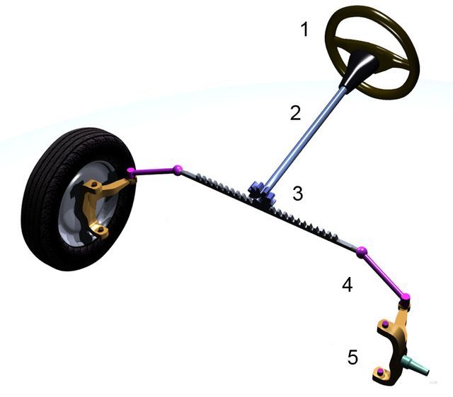
As we all know, most steering systems use a rack and pinion system - that is, the steering wheel is connected to a shaft which carries a pinion gear at the end. The pinion engages with a rack - on the ends of this rack are tie rods which connect to the hub carriers. When the pinion is rotated the rack moves in a linear fashion within the steering rack housing thus steering the wheels. The image below shows a basic manual steering rack layout,
Moving on from that, nearly all cars now have whats called power assisted steering. These systems can be hydraulic assist or electric assist. For the purposes of this thread, and taking into account the Redbull part in question is hydraulic assist, that is the system we shall be concentrating on.
Hydraulic assisted power steering uses a few components.
1.Hydraulic Pump to provide system flow/pressure.
2.Spool Control Valve.
3.Rack capable of turning the oil pressure in the system into linear motion to steer the wheels.
The image below shows a basic hydraulic assisted power steering rack layout,
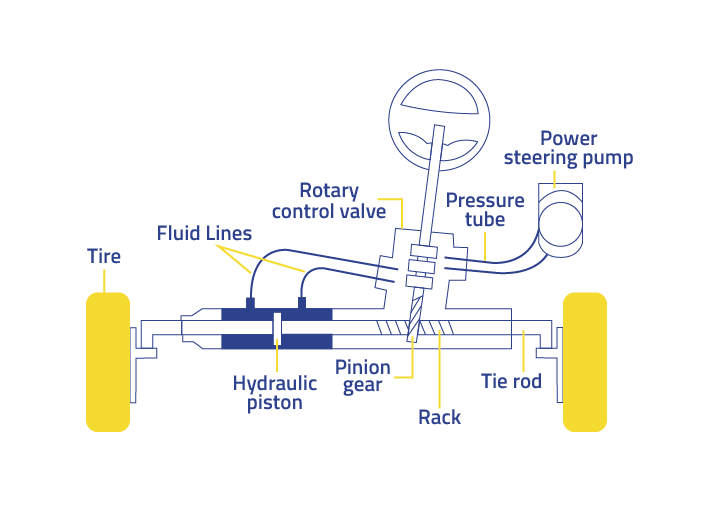
As we can see the spool valve directs the fluid to chambers either side of a piston connected to the rack. This fluid when pumped into either the right or left chamber pushes on the piston and causes the rack to move in that direction. For example, if it is pumped into the left chamber above, it will cause the rack to move in a linear fashion to the right.
Digging a bit deeper into the spool valve and pinion operation it is probably apparent that the above diagram is just a representation of the layout. The diagram above shows the pinion shaft in the steering rack as one piece surrounded by the spool valve.
If the spool valve was directly mounted onto the pinion shaft and the pinion shaft one piece, then the rotational movement from steering wheel to pinion would mirror the workings of the manual steering rack described earlier and any hydraulic assist would be pointless since all the work is still being done anyway with the rack and pinion.
So to combat this, a rotary motion delay needs to be built into the pinion shaft between the spool and the pinion.
This delay then means that the spool has time to ''see'' what rotational motion is at the input, before the pinion does.
In conventional power steering systems this 'rotary motion delay' feature takes the form of a long slender torsion bar inside the two piece pinion shaft as shown below,
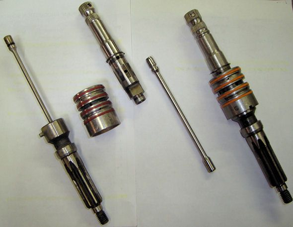
On the far right above we can see the assembled pinion and spool valve.
The three parts on the left above are the lower pinion shaft, the torsion bar, and the spool valve.
The part in the middle is the input - upper pinion shaft.
The upper and lower pinion shafts locate together axially by means of loosely fitting dog features. This feature can be seen on the lower end of the upper pinion shaft(middle of photo). These dogs never normally transmit any rotating motion from the upper pinion to lower pinion shaft and would have maybe 10 degrees of rotational play. They are there for when the car is turned off, when the hydraulic system fails, and when the steering is on full lock. In an ideal world, there would be no need for these loose fitting dogs and the torsion bar would suffice on its own.
(Worth noting, many tuners often convert a power assisted rack back to manual for preferred steering ratios by disconnecting the hoses and capping the ports. This is not how to do it correctly as the system will have play since the output pinion is being driven via the loose fitting dogs - the two shafts must be welded together)
Inside the upper and lower pinion shafts lies the torsion bar. This torsion bar is fixed at either end to both upper and lower shaft parts with small 3mm cross pins as can be seen. Once the upper and lower pinion shafts are assembled it should now become clear that the torsion bar provides torsional elasticity from the input, to output/pinion.
Since the pinion is in mesh with the rack - which requires a far bit of force to move linearly, any input to the upper shaft causes the pinion shaft assembly to 'wind up' a few degrees.
Given that the spool valve is attached to the lower pinion shaft with a cross pin, and the corresponding oil ways matching the internal features of spool are machined into the upper pinion shaft this torsional elasticity between both parts allows for oil to flow depending on rotational orientation with each other.
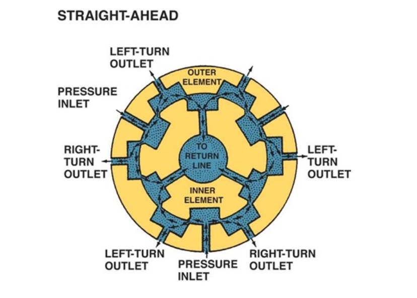
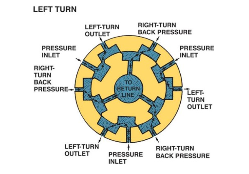
A plan view cross section below of upper pinion shaft (center) and outer spool valve part, and oil paths at various positions,
And with wheel turned,
Since the torsional windup of the pinion shaft assembly depends on the resistance the lower pinion shaft sees at rack interface, once the spool valve has directed the oil to either chamber at rack piston the rack then moves to position and equilibrium is thus reached between lower pinion shaft, and upper pinion shaft and the spool rests in its ''straight ahead'' position even if wheels are turned to left or right.
Having taken all of the above into account we can now progress onto the F1 Steering Rack Control Valve with a better understanding of features, and also on how it differs from a normal road car.
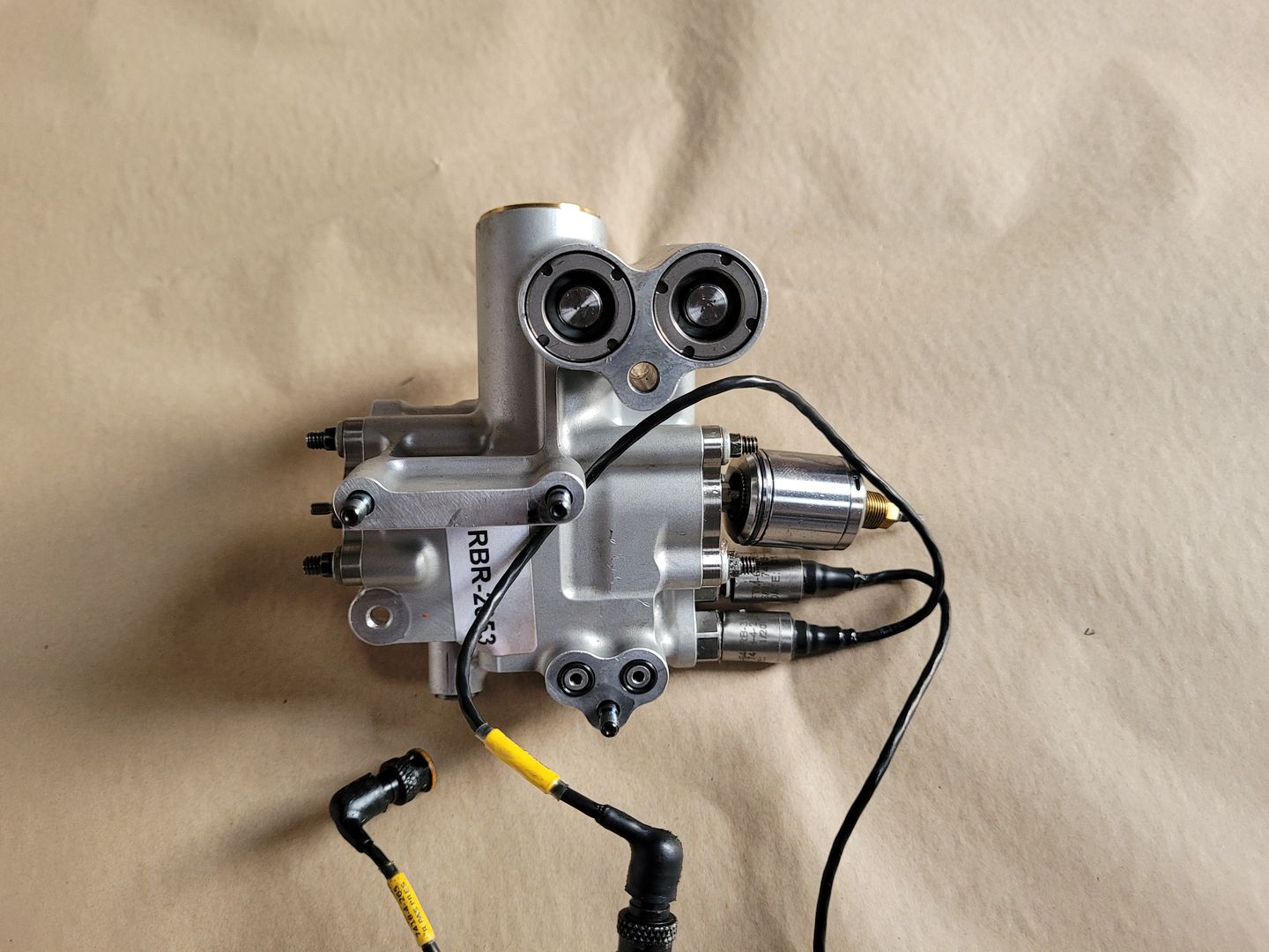
The part below is from the RedBull F1 RB4 (2008). It is very clear it features an axial spool valve,
A bit of searching brought up a few pictures and from those the research below started which ended up being possibly the largest body of work ever done to date on an F1 part in order to create a technical post.
Obviously it is well known how a hydraulic power assisted steering rack works as outlined above but F1 Steering racks are very different. In the end, a rough cad model was generated from many pictures gathered online. Motion Simulations were added gradually to this rough cad model based on each part having one function/possible motion given its location - basic application of classical mechanics if you will. Following on from this it was clear for certain as to how the rack functioned then.
So first off some pictures of various racks in F1 cars. As you are probably aware it is extremely hard get photos of the car in this area since the nose cone has to be removed,
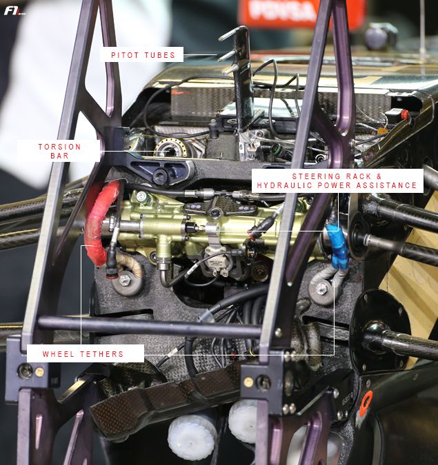
A Lotus F1 car, nose off, a closer look you will notice end of axial spool valve is connected to a silver part,
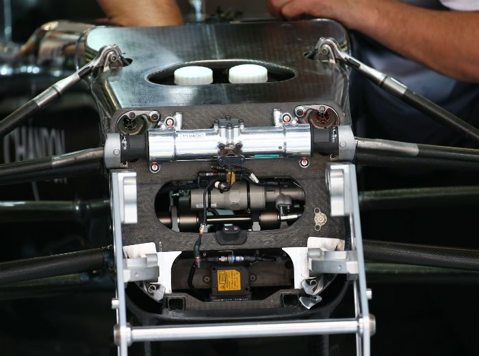
A later Redbull car, nose off,
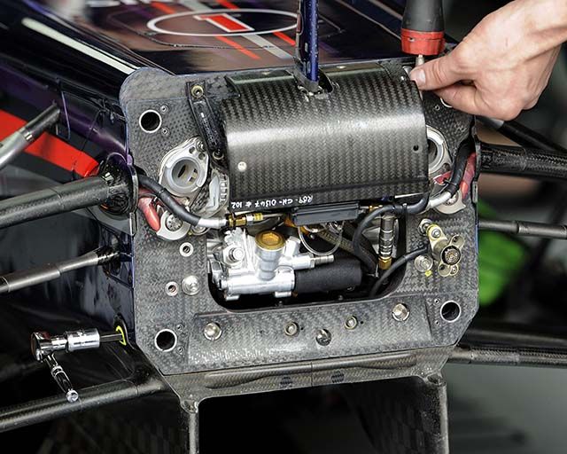
Finding this image was a huge breakthrough however it leaded to further confusion,
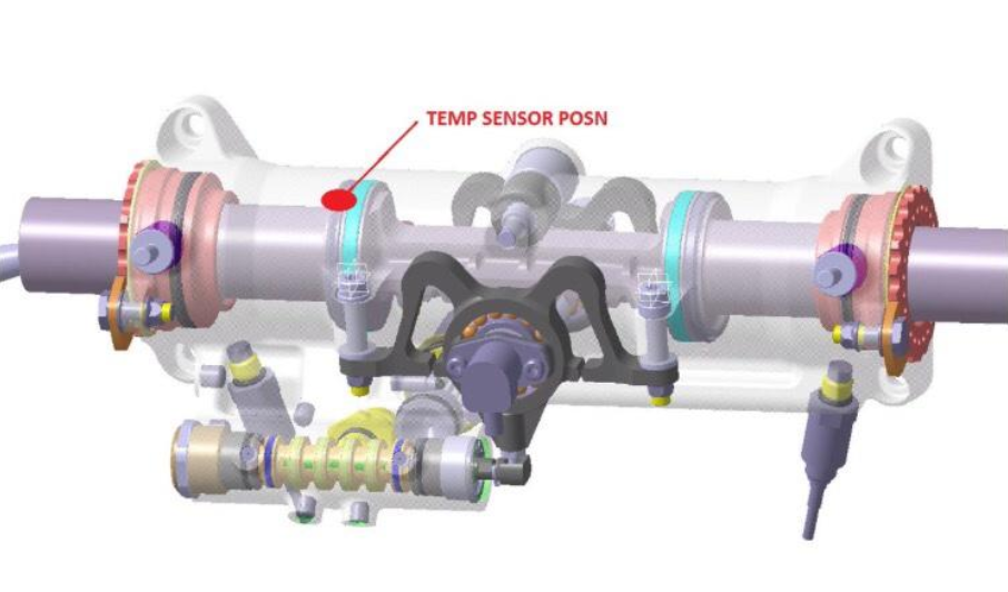 Image credit @KevTs
A great photo also, however again, lead to confusion,
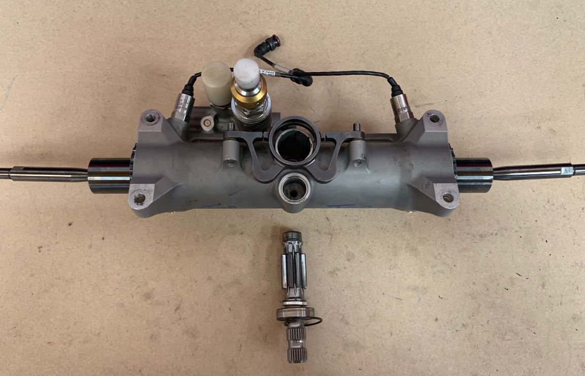 Image credit @KevTs
The issue regards understanding function at first glance is to do with the control spool axial displacement, it is only +/- .75mm. Remember, the F1 spool which we will look at shortly has the same function of the basic rotary spool mentioned earlier in thread - it has to see the steering spindle input before the pinion does in order to provide fluid assistance to rack.
The area of concern below,
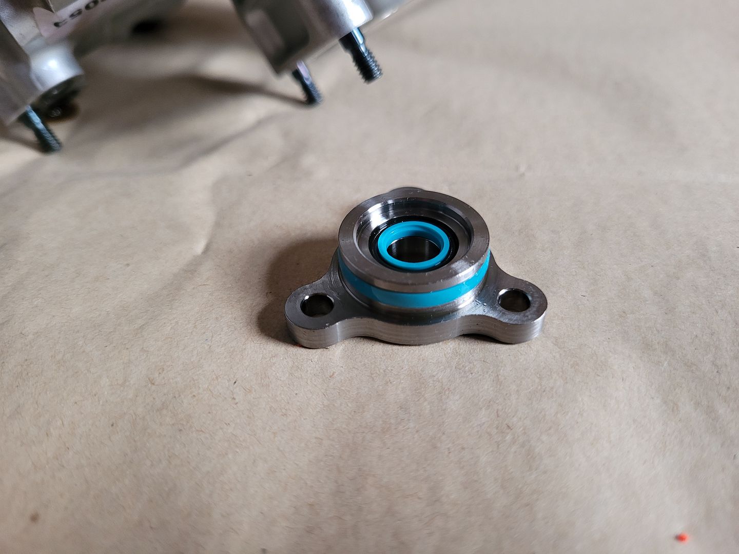
The grey part looked to be fixed to end of pinion shaft - but it couldn't be - the spool would only allow grey part to rotate a few degrees either way - severely limiting steering lock! If the grey part sat on end of pinion shaft on a bearing as it looks like it does above, then the pinion end would just rotate freely inside it, while at the same time being constrained by the bearings in the main rack housing.
The grey part sitting on end of pinion shaft and controlling spool axial displacement was modeled in cad and motion applied to the system, below is the full cad model displayed,
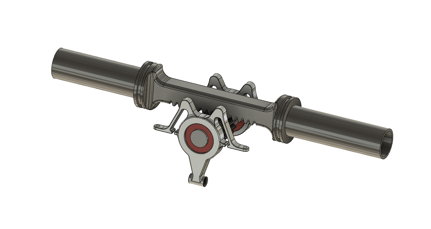
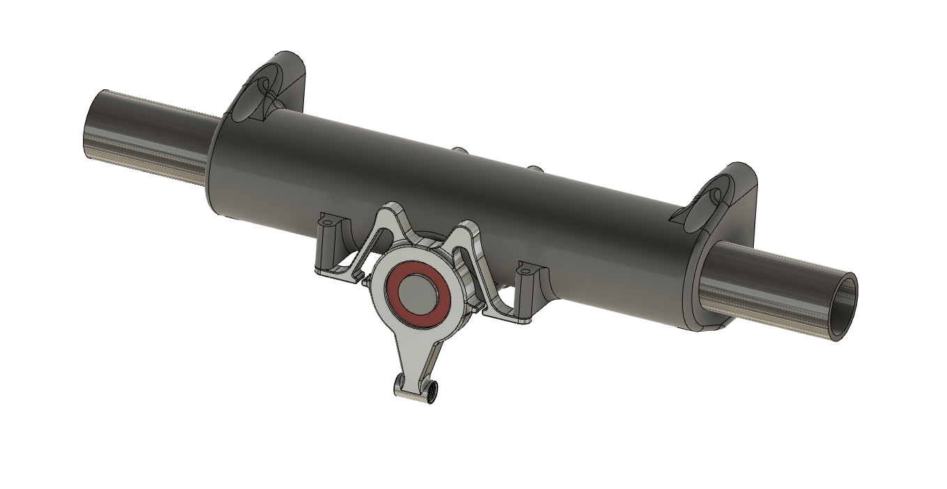
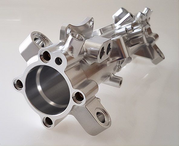
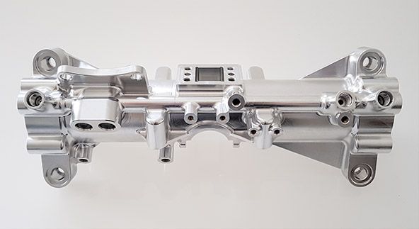
The main casing was loosely modeled on a part found online made by an Aerospace Company in Italy - the part is 2014 series billet aluminium and looks to be a Redbull item from studying various spool valve mount locations,
Many simulations and constraints were ran with not much success,
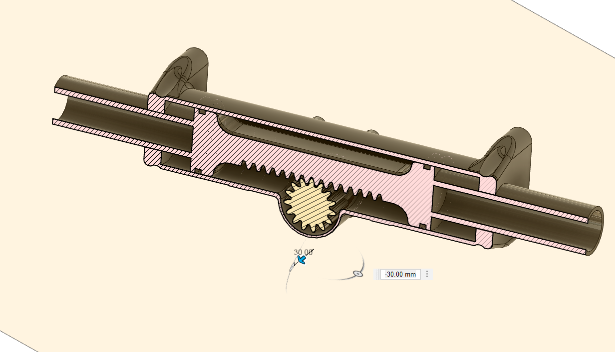
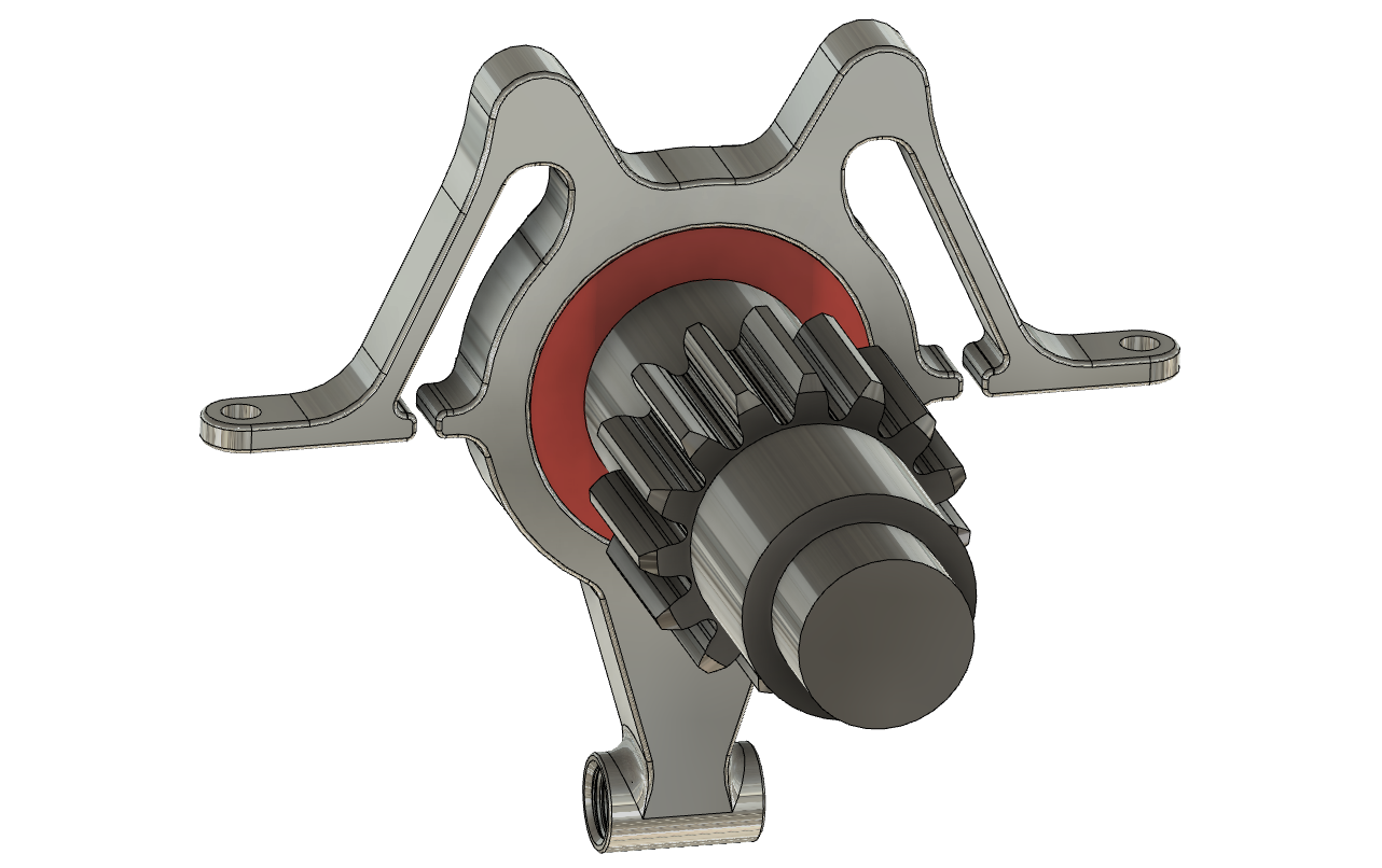
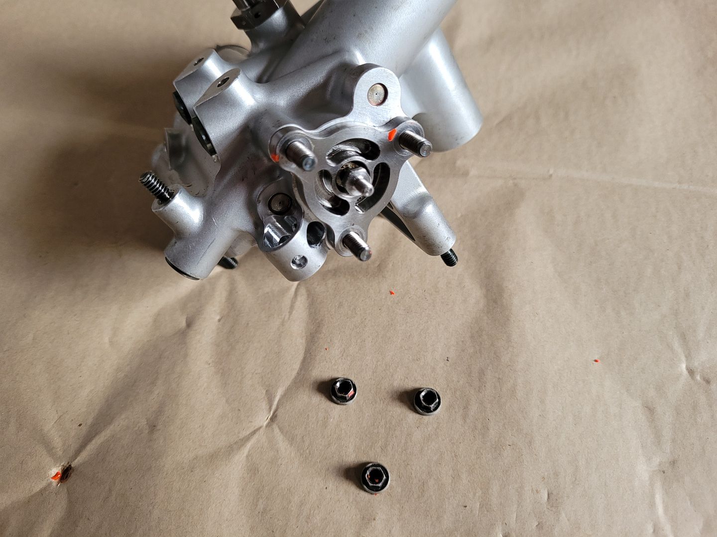
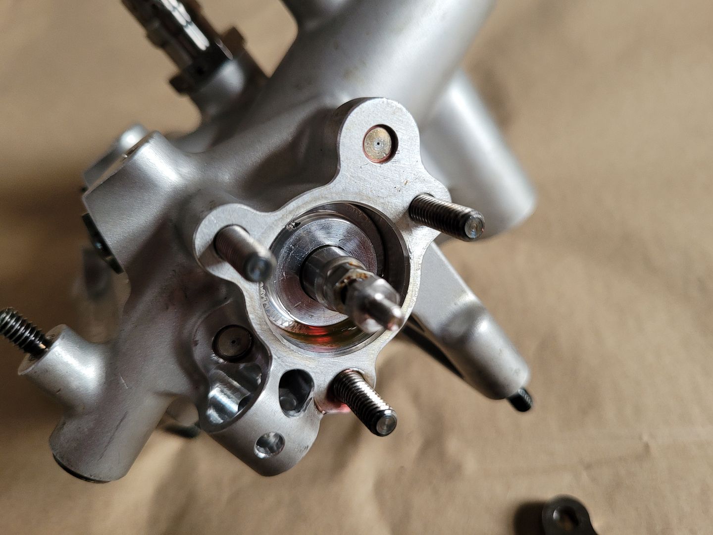
Finally a realization was made - it turns out that the pinion shaft is not actually running in bearings in the main housing above at all, and instead just sitting on the what is now known as two flexure mounts at the front and rear of the housing,
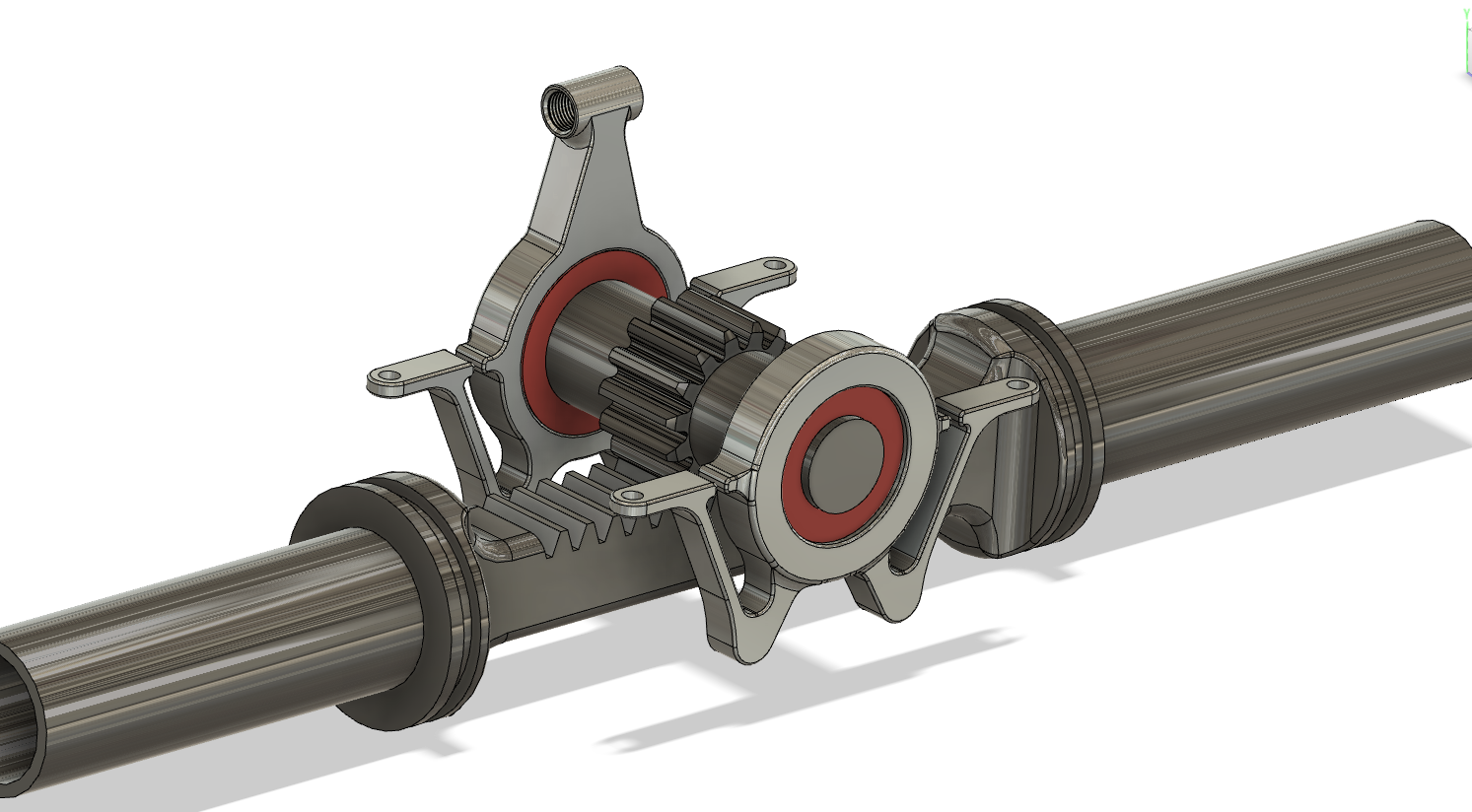
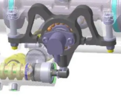
A closer look at the flexure mounts which were modeled up from the pictures shows two important breaks either side of pinion bearing housing area. These gaps allow the pinion to float from side to side.
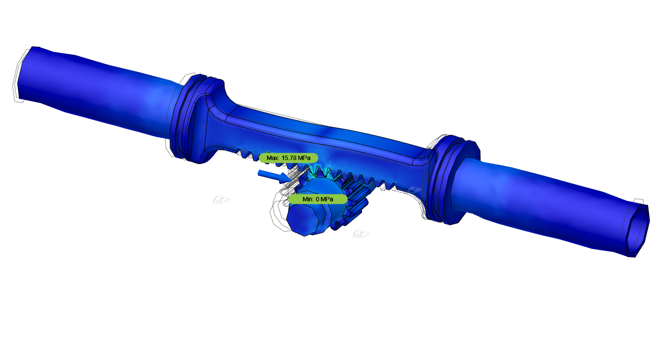
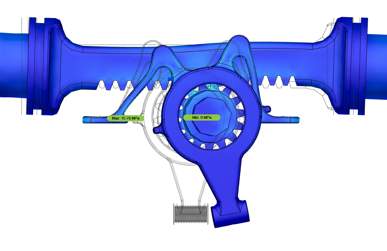
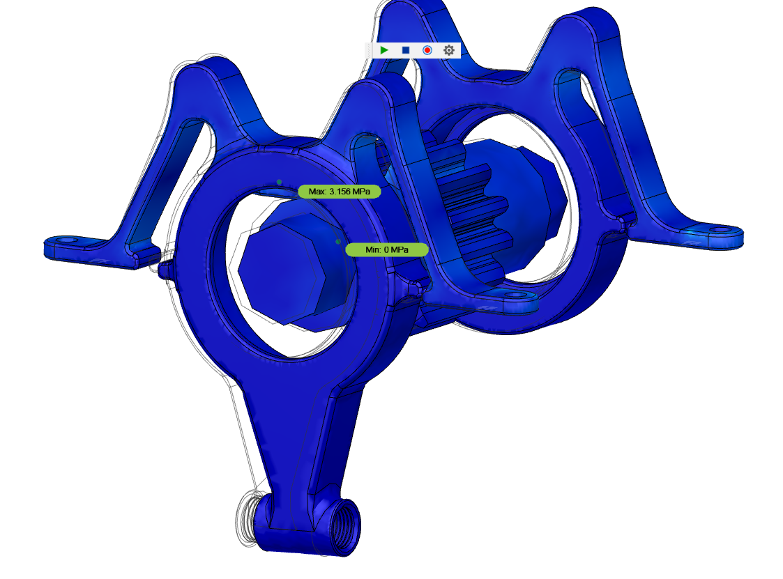
Taking it into motion study and running a deformation simulation on the assembly, it is now clear on how the spool valve is axially displaced. When the pinion is rotated by the steering wheel, the resistance provided by the rack/contact patch of the tyres causes the pinion to move to the left or right as it tries to travel along the rack. The flexure keeps the pinion firmly engaged with the rack in the z direction but allows pinion float in the x direction, in turn actuating the spool valve and in turn supplying fluid to whatever side of the rack chamber the pressure is required to move the wheels and put the system back into equilibrium again.
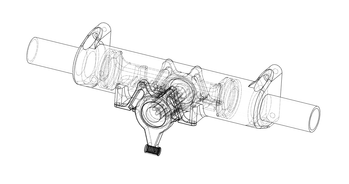
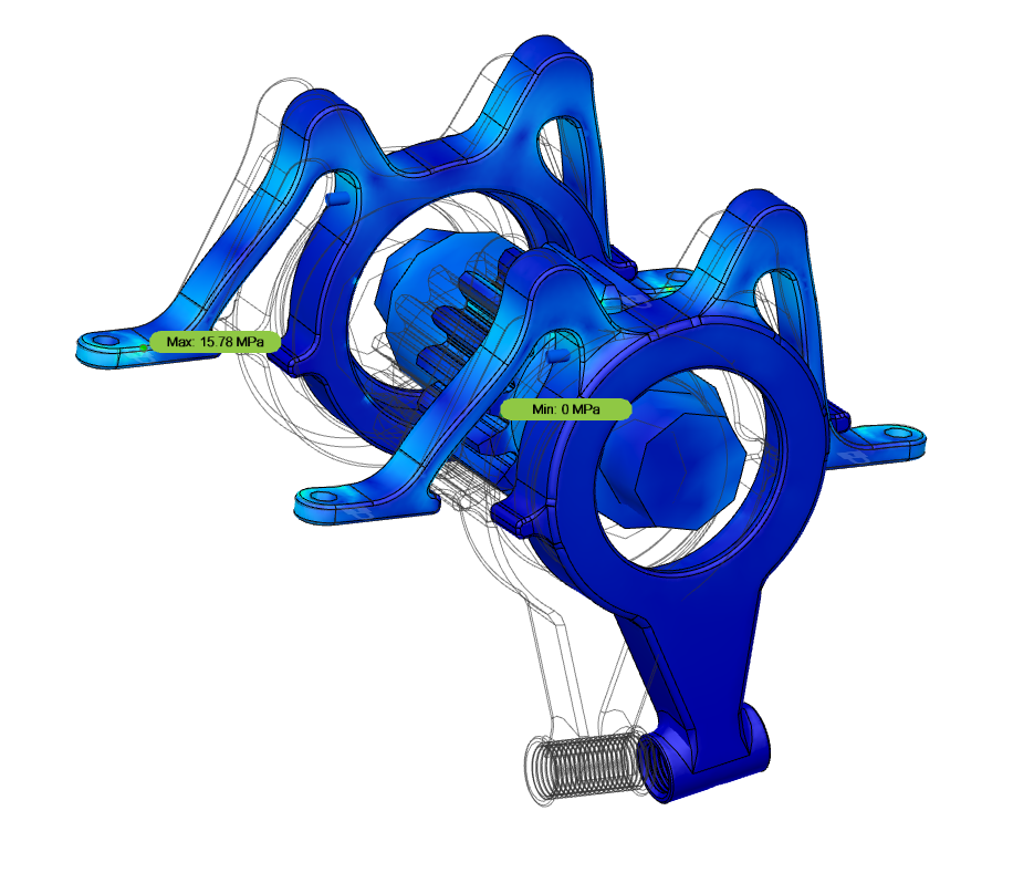
A large amount of displacement first for display purposes,
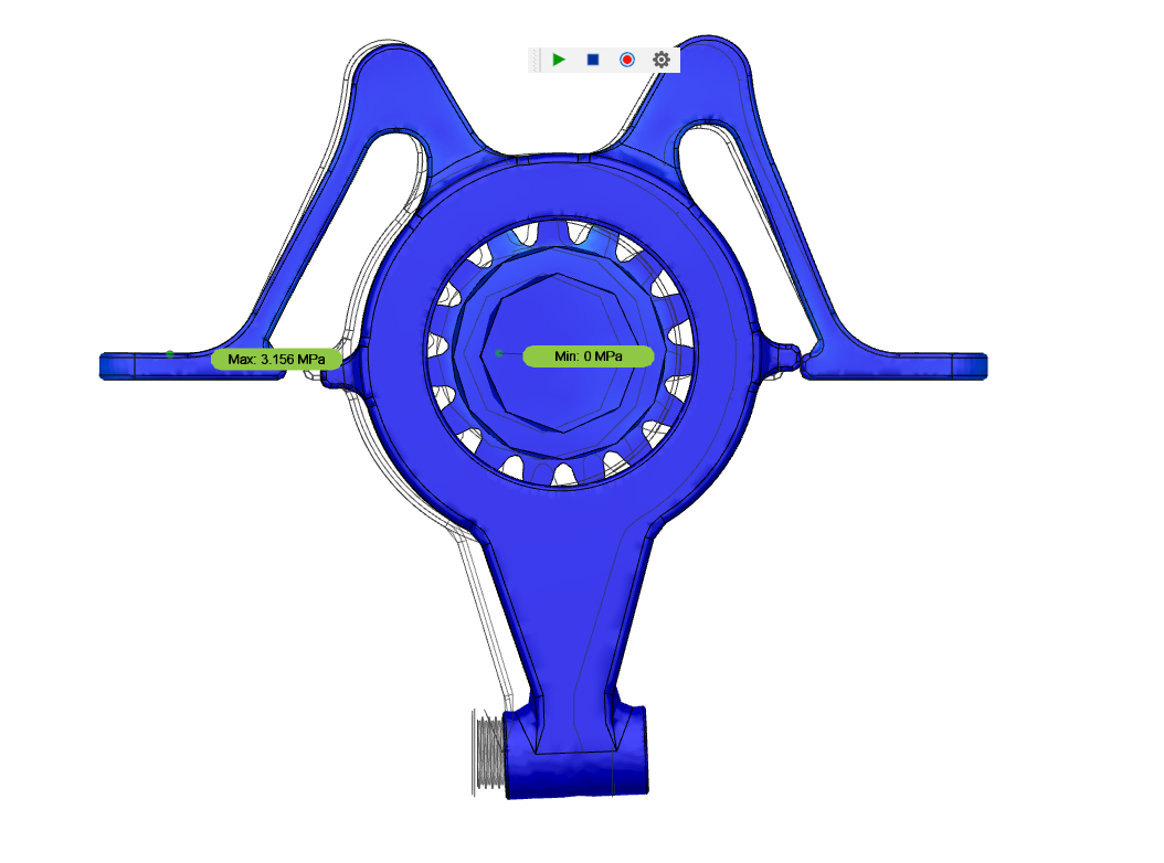
Then a more real amount of deflection - ignore values, they are meaningless,
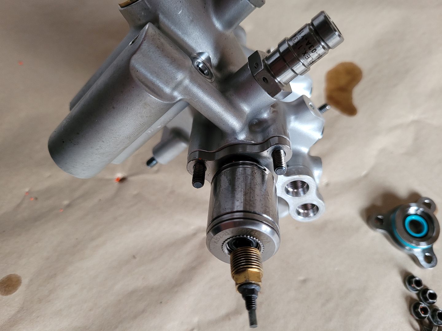
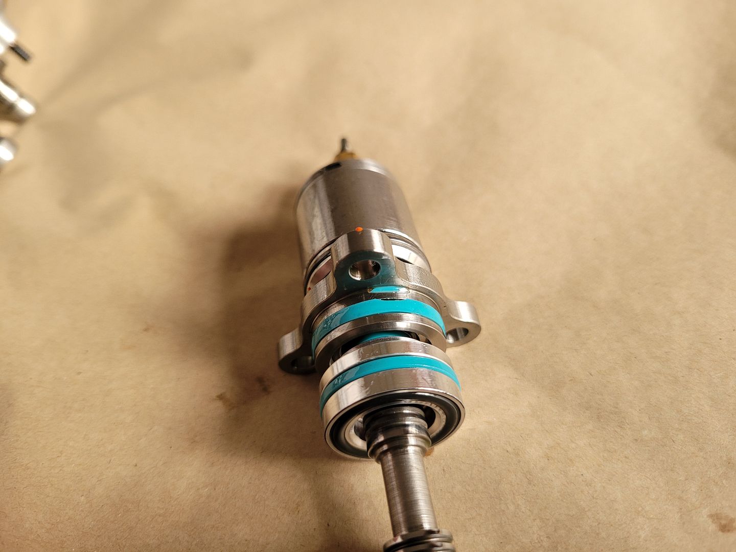
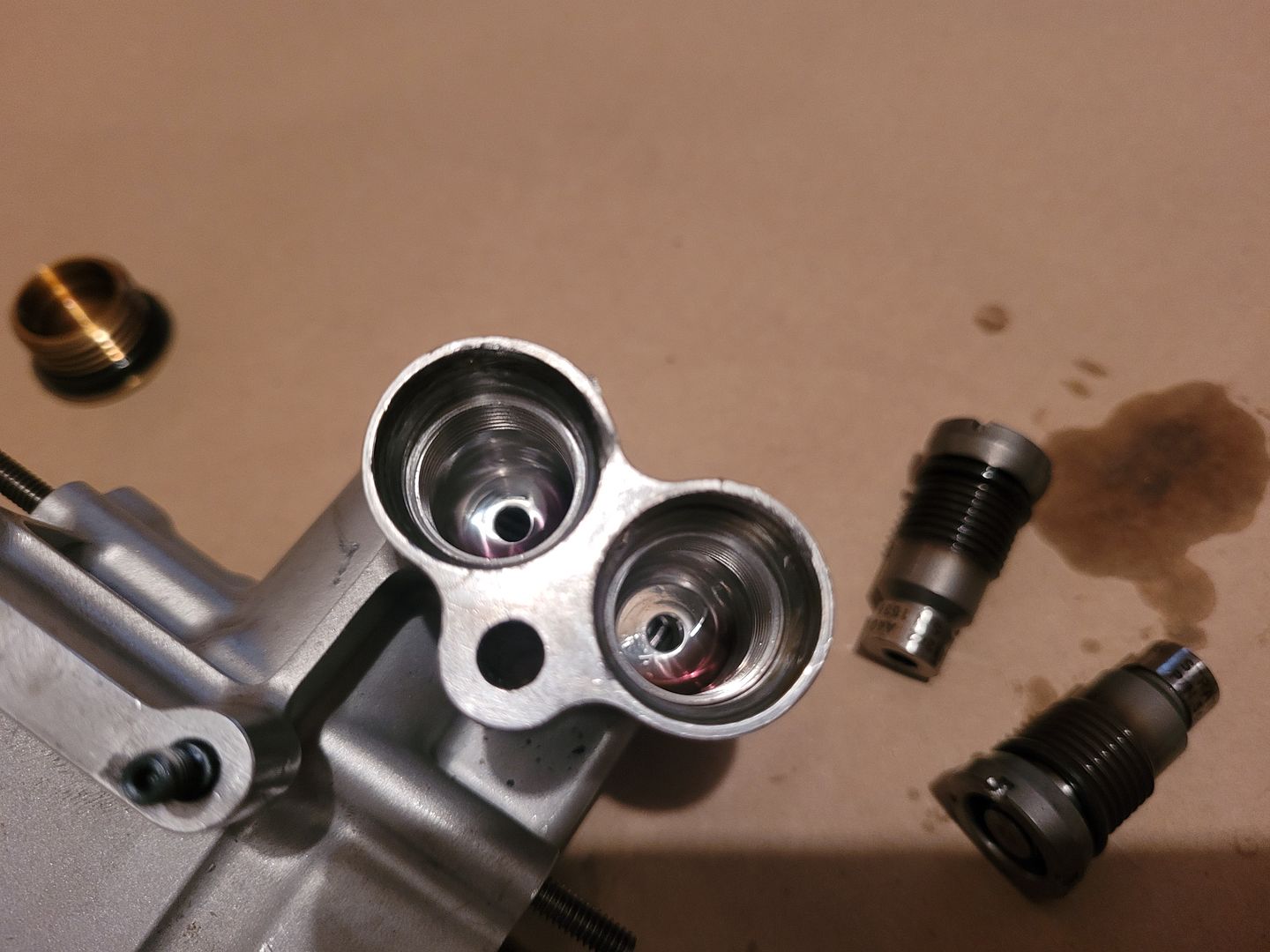
So with all that understood, lets take a look at the spool valve itself, it is a pretty compact part - approx 100mm wide,
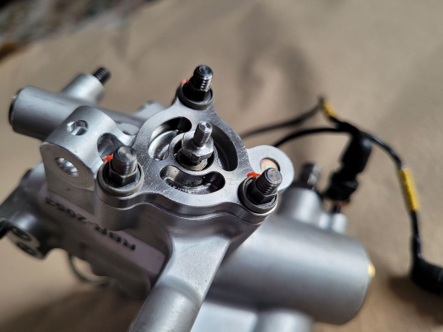
Machined from 2 series aluminium billet,
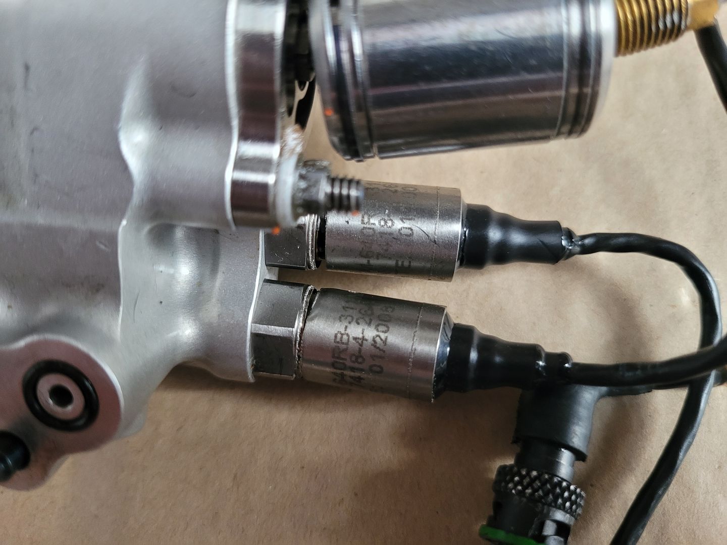
The two small lower ports are oil entry/exit into main rack housing,
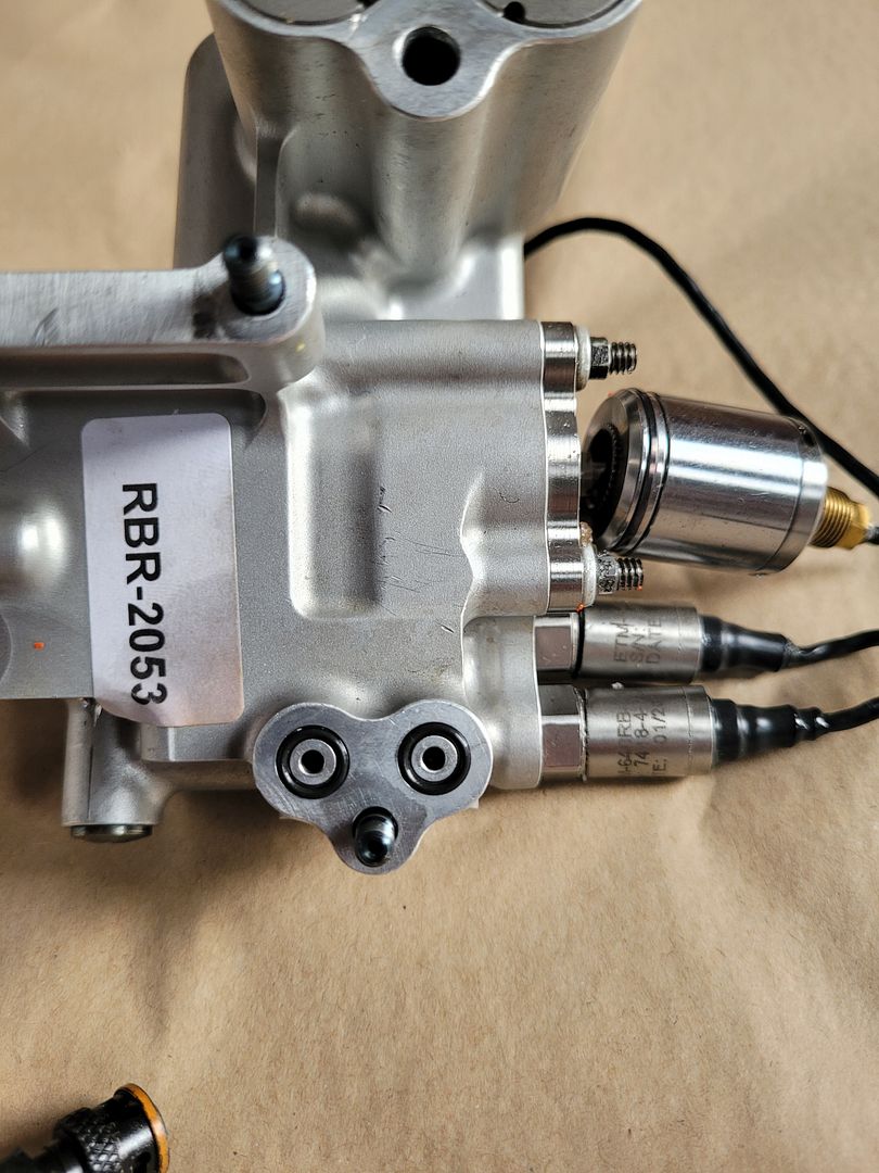
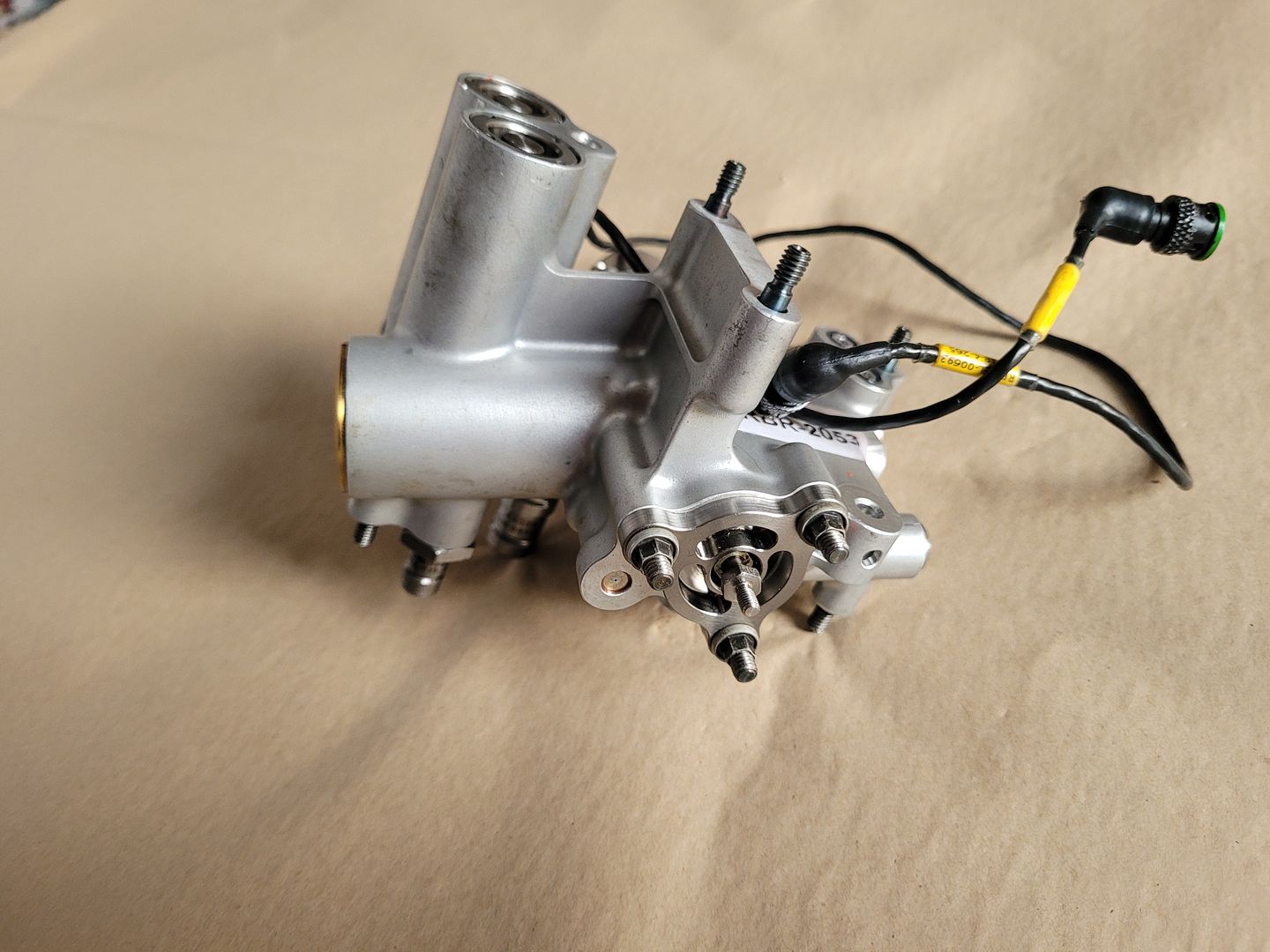
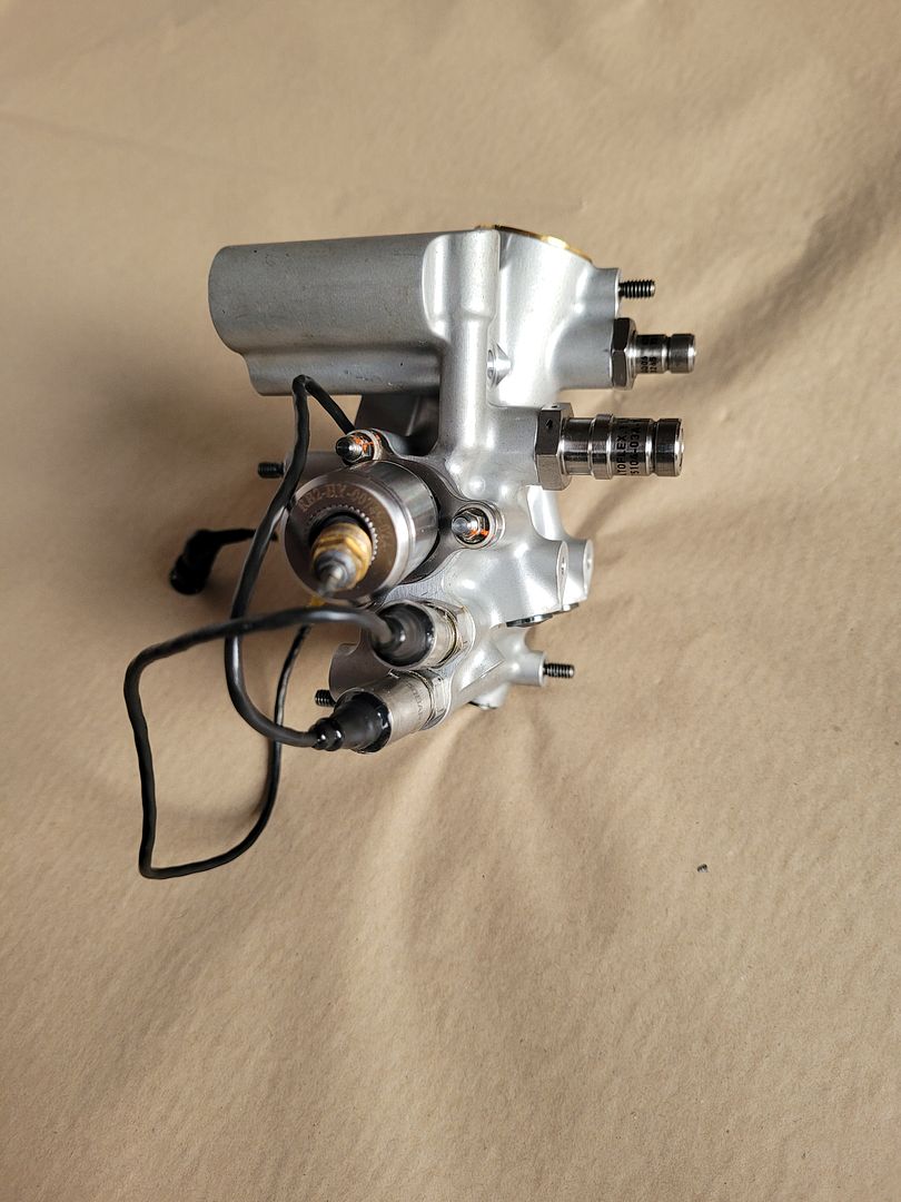
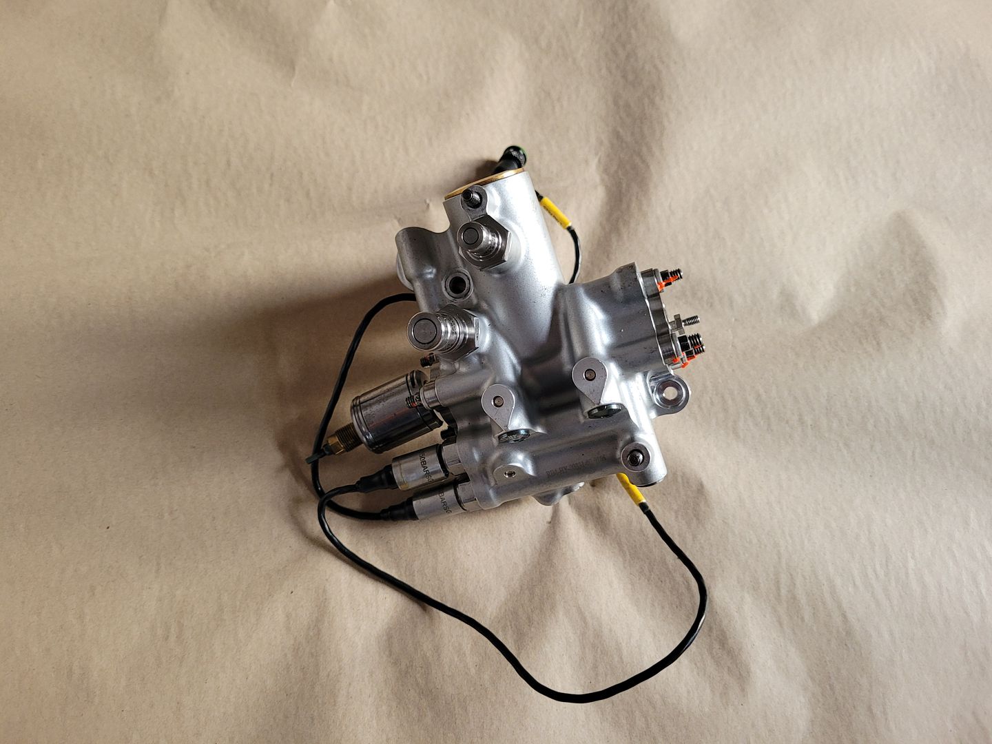
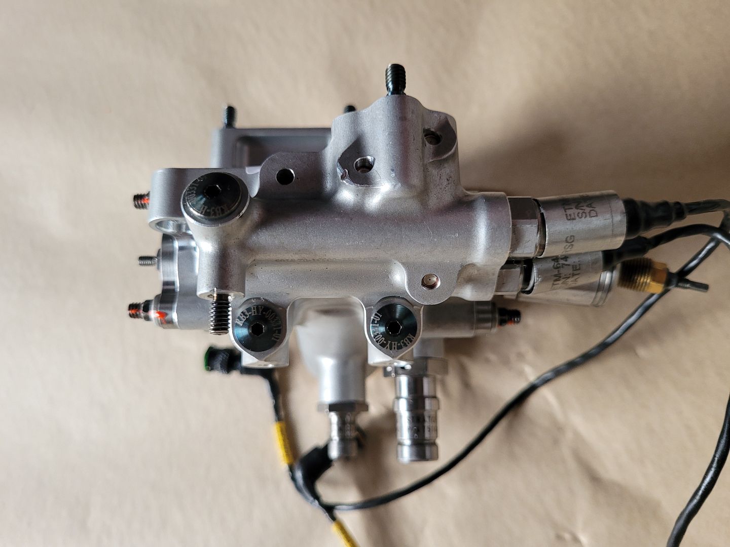
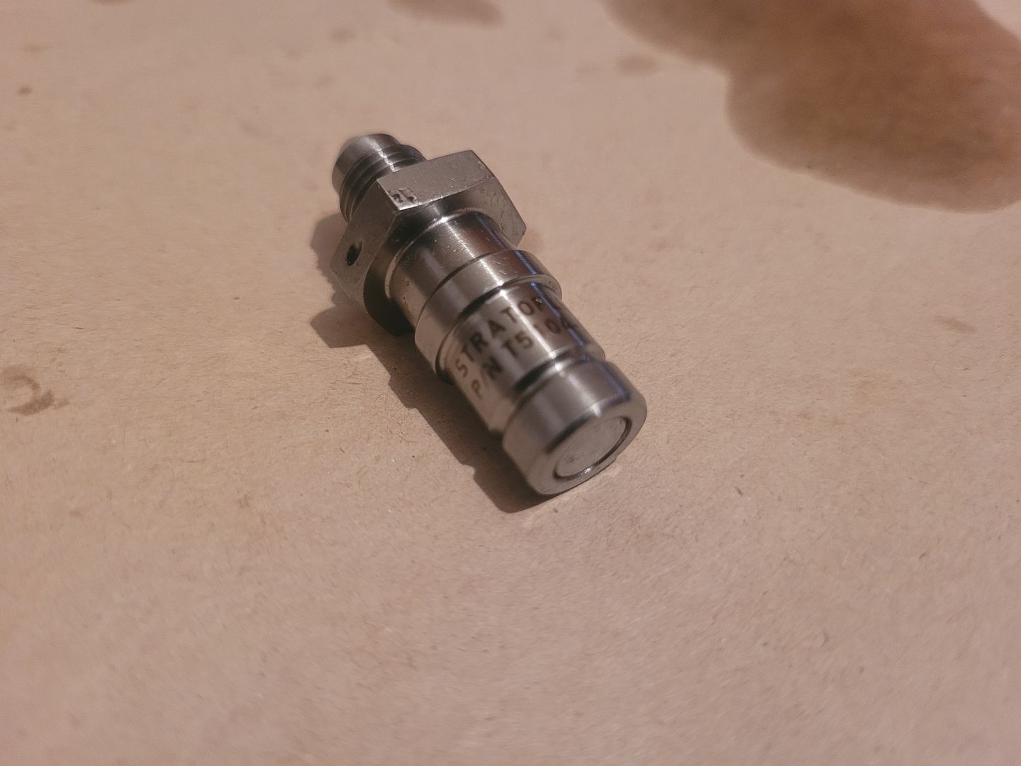
The end of axial spool where it connects to flexure, there are two ball joints here given the motion translation required from the flexure,
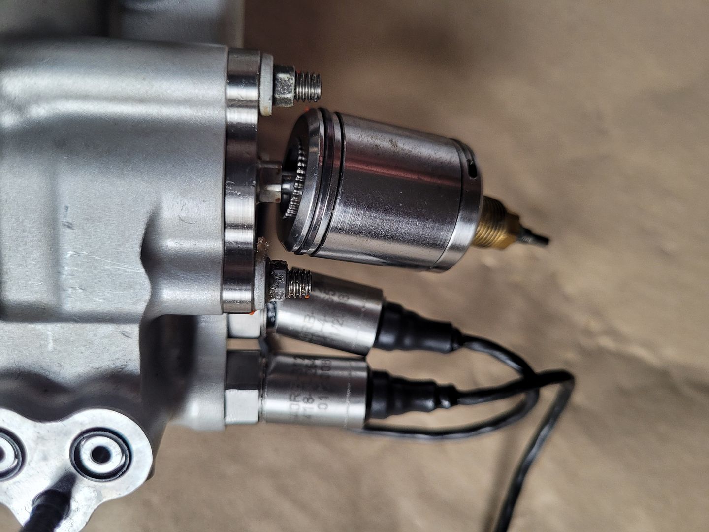
The steel barrel part appears to be a tuned mass damper - its solid steel. Possibly needed to tune out any vibrations that maybe present in the flexure during high frequency bump steer events or such other vibration/harmonic/hysteresis type events across the mechanical to fluid link.
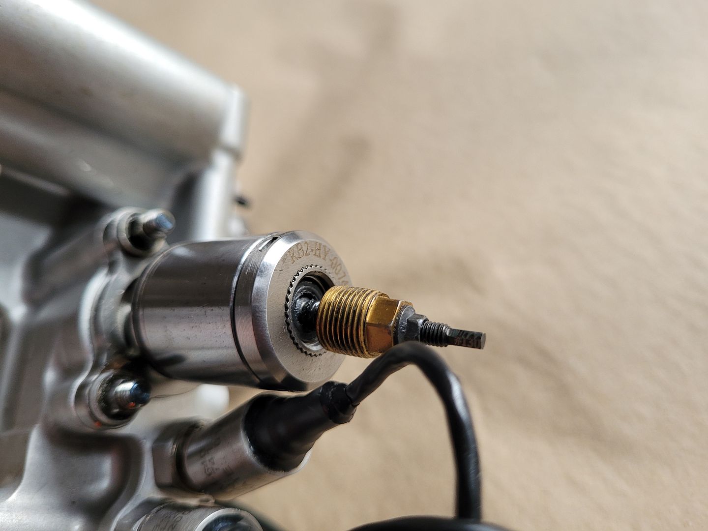
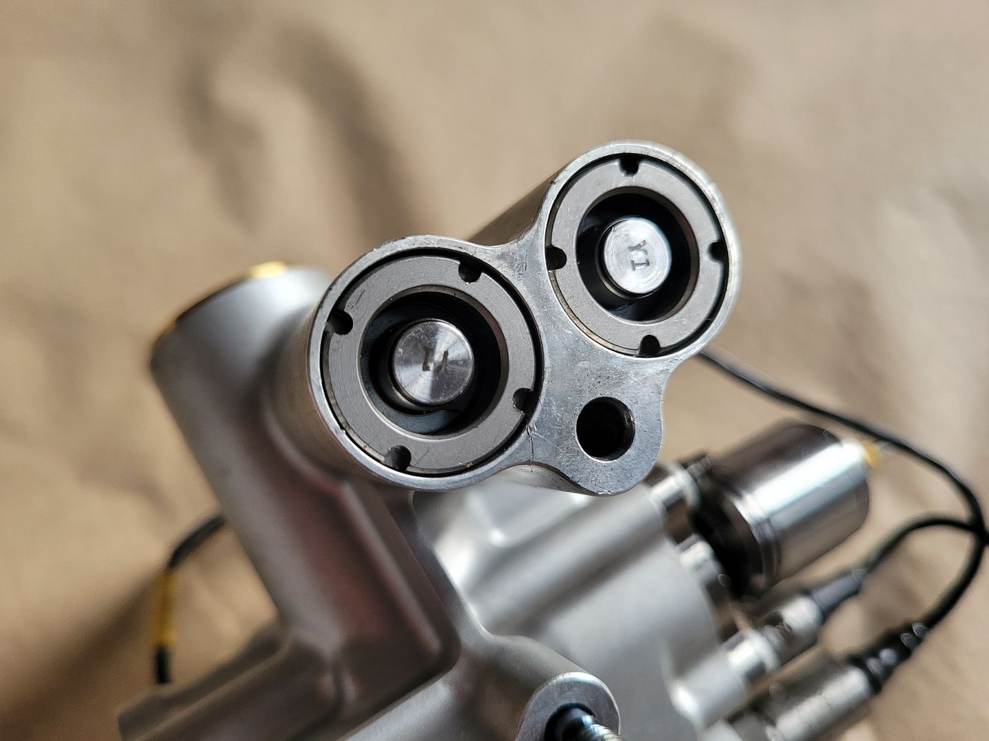
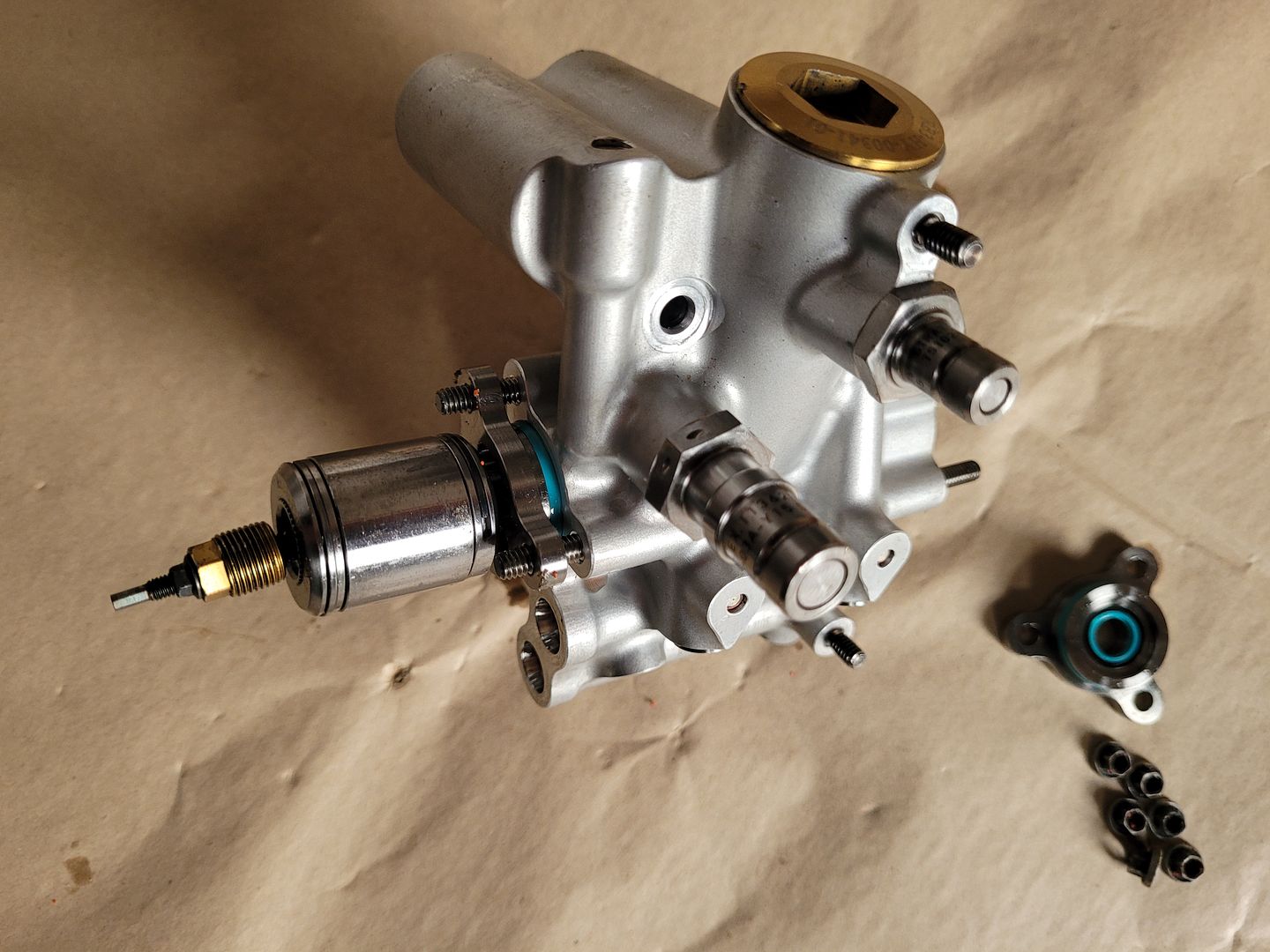
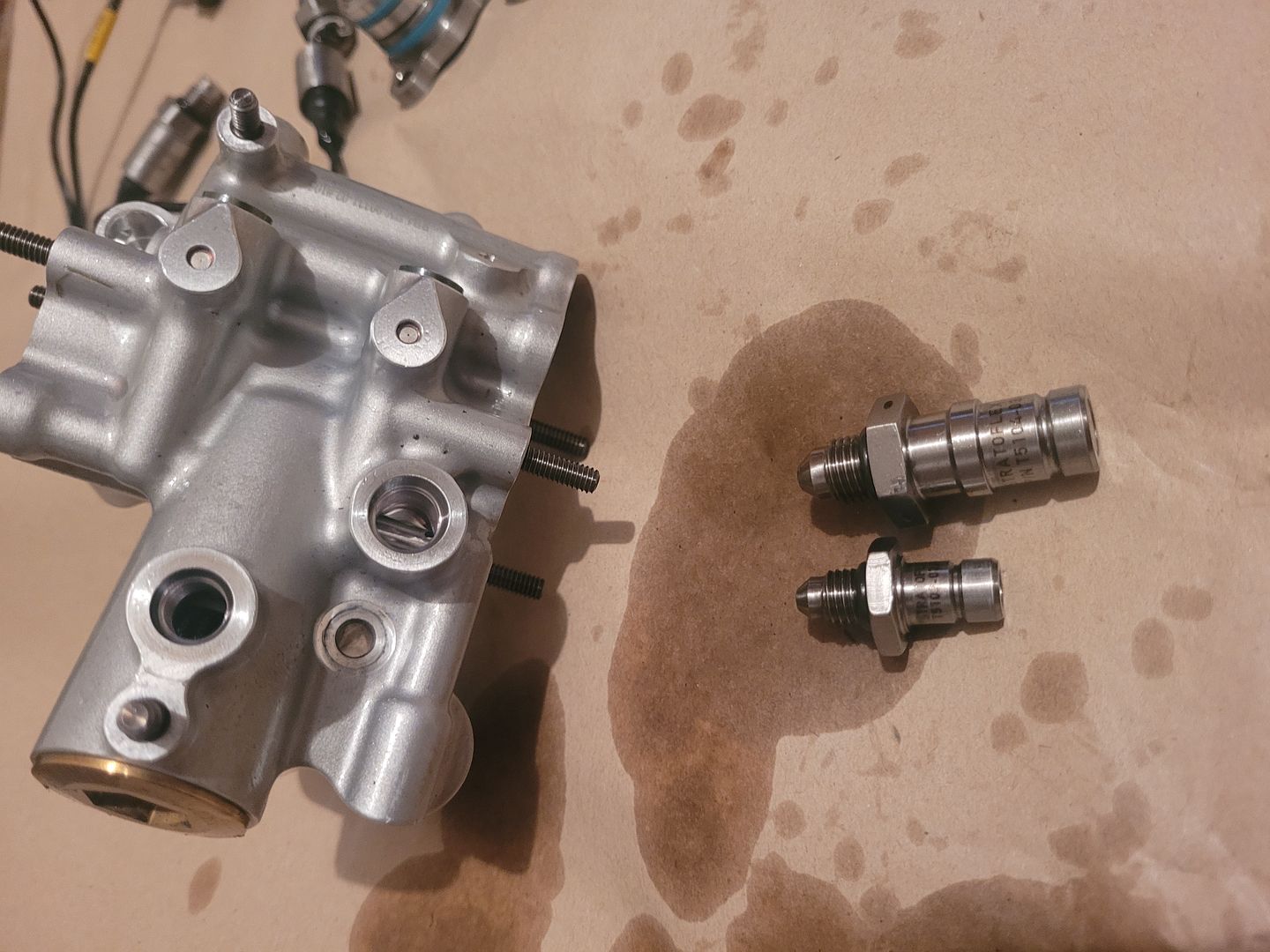
The male dry break connections,
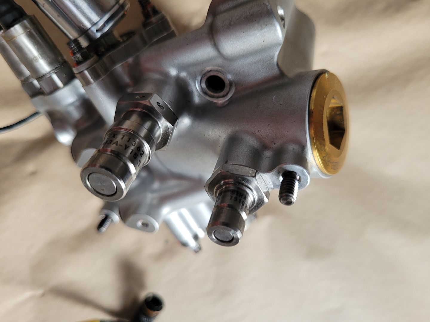
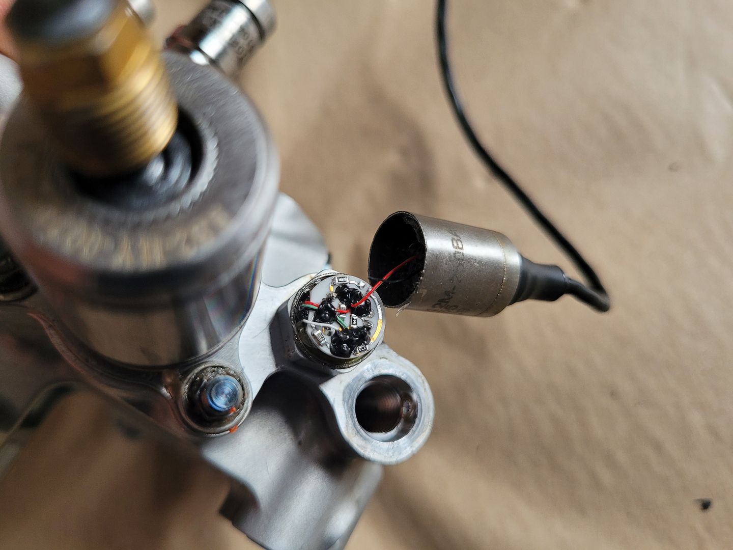
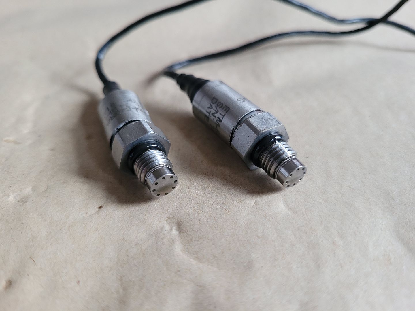
The pressure sensors (broken) - two of, each monitoring fluid in both rack compartments,
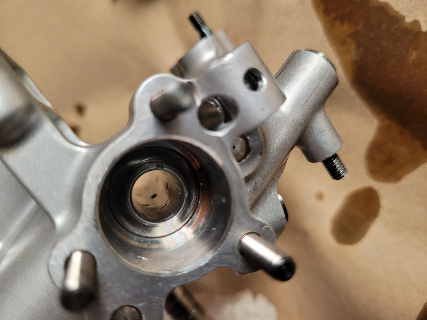
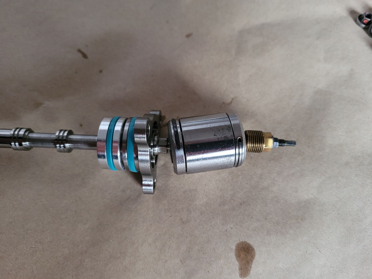
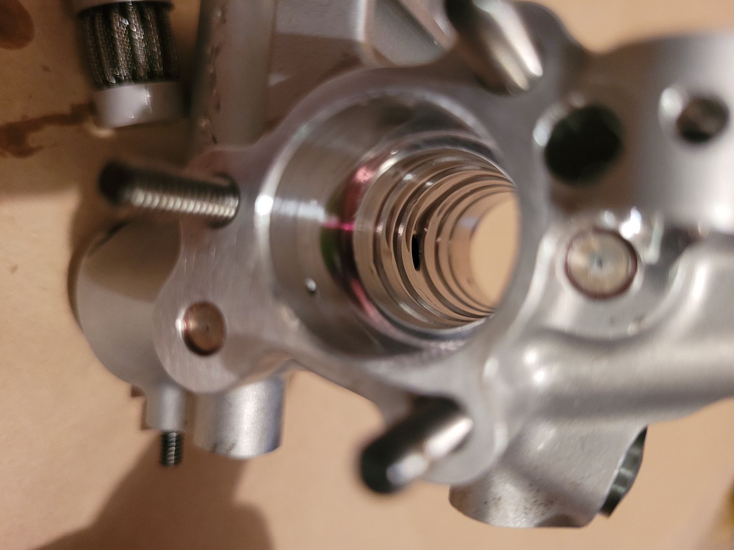
Removing the spool valve end retention plate, titanium part,
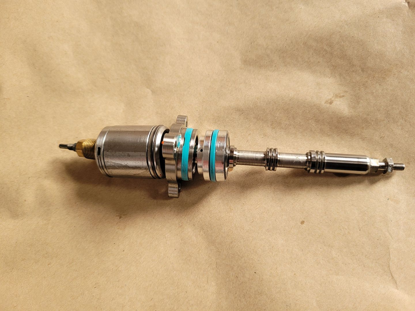
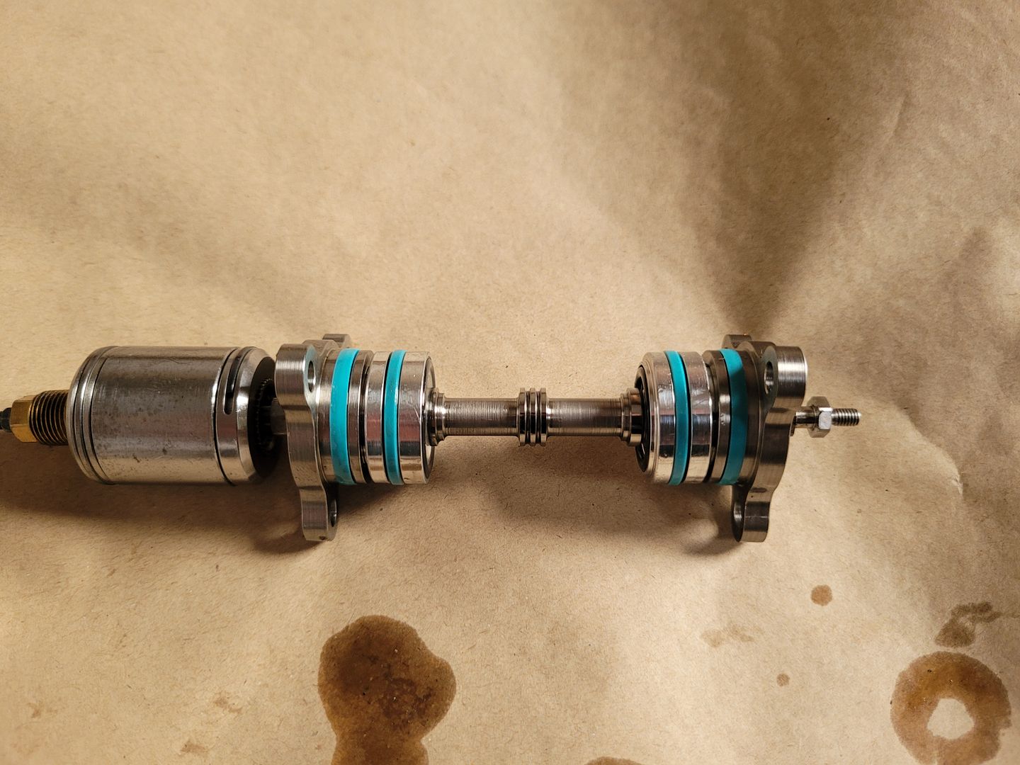
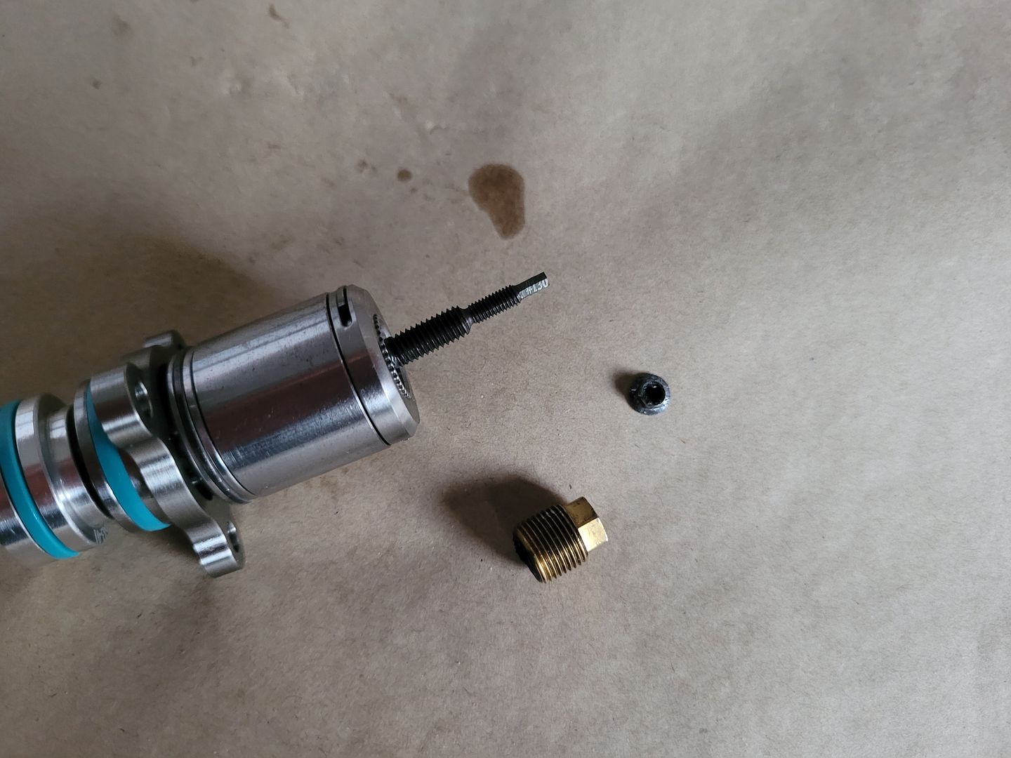
Removed other end plate, allows the spool center shaft to be removed,
Interestingly, on inspecting the housing chamfer detail it was not fully deburred and had damaged the seal at time of assembly, pretty surprising on a part like this,
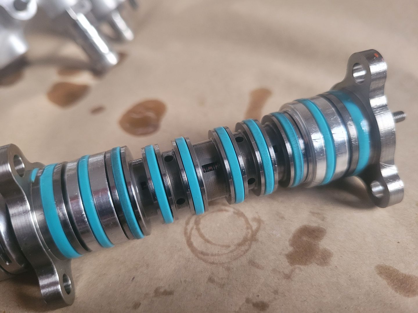
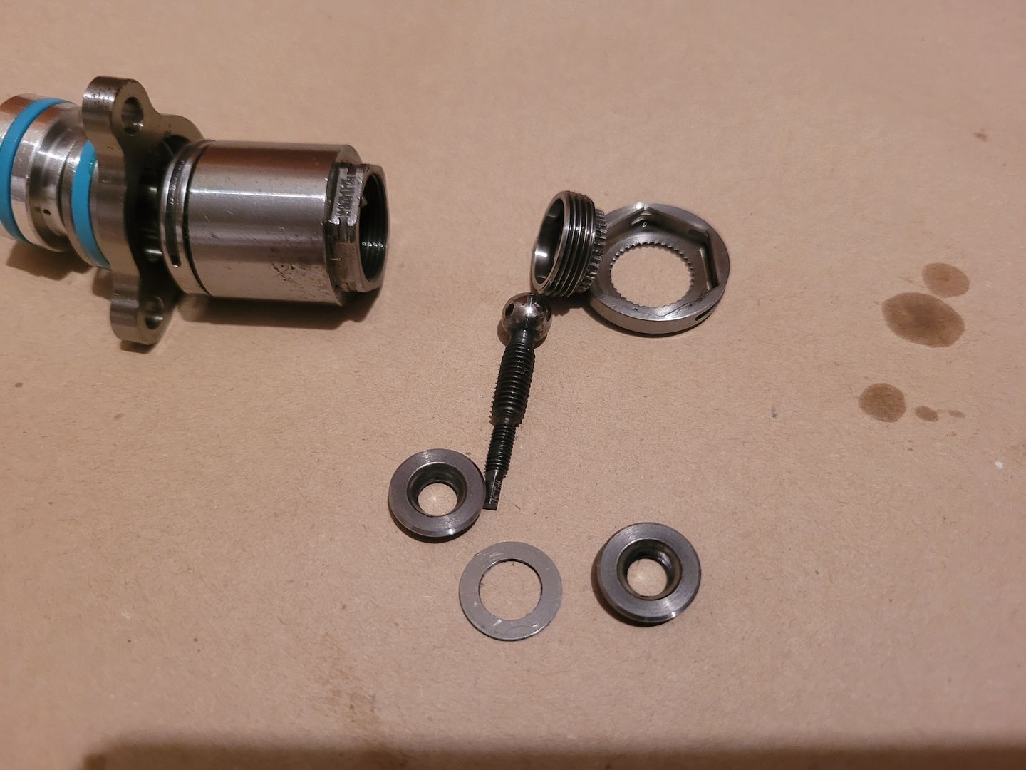
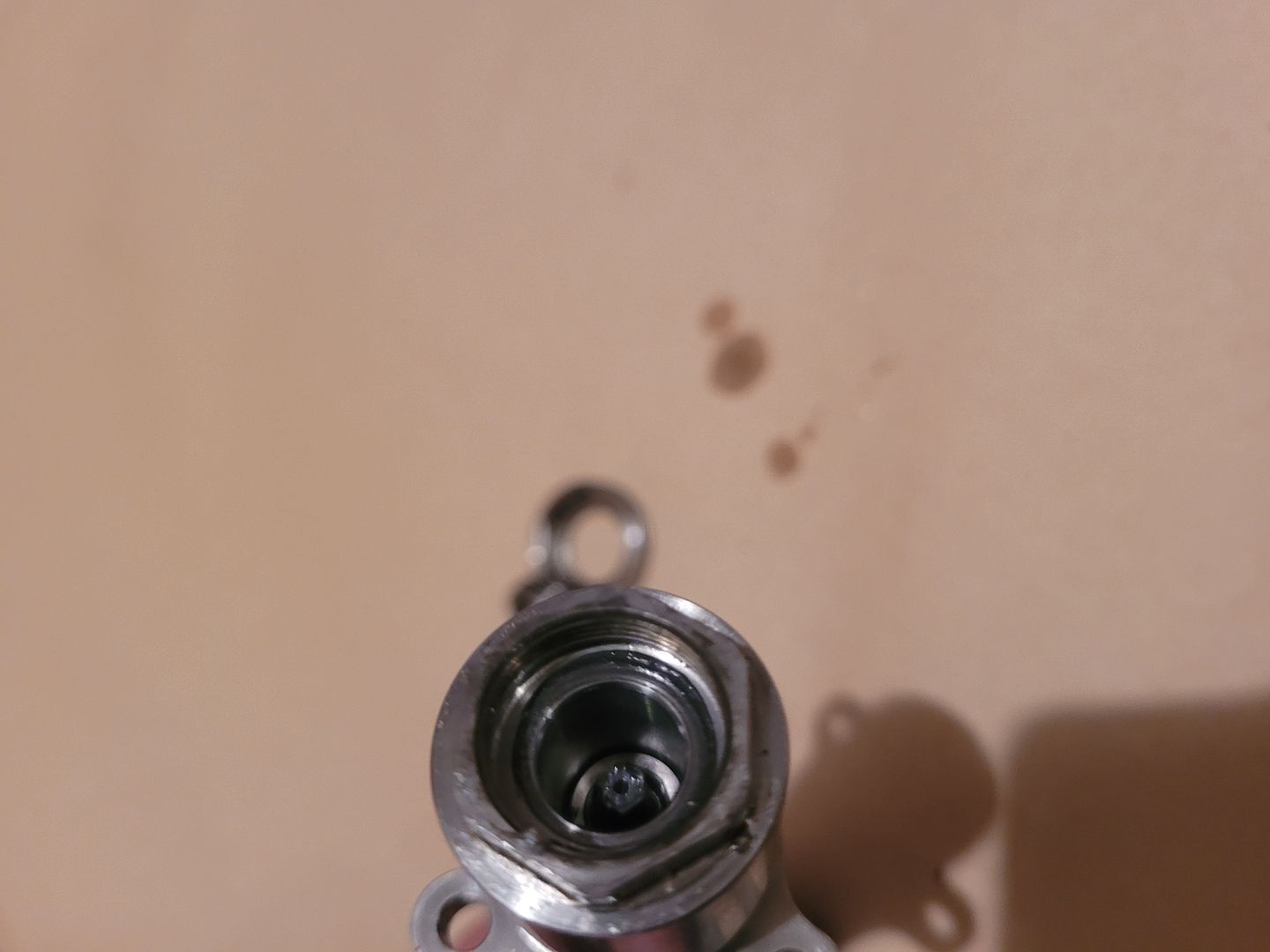
A close up of the center shaft,
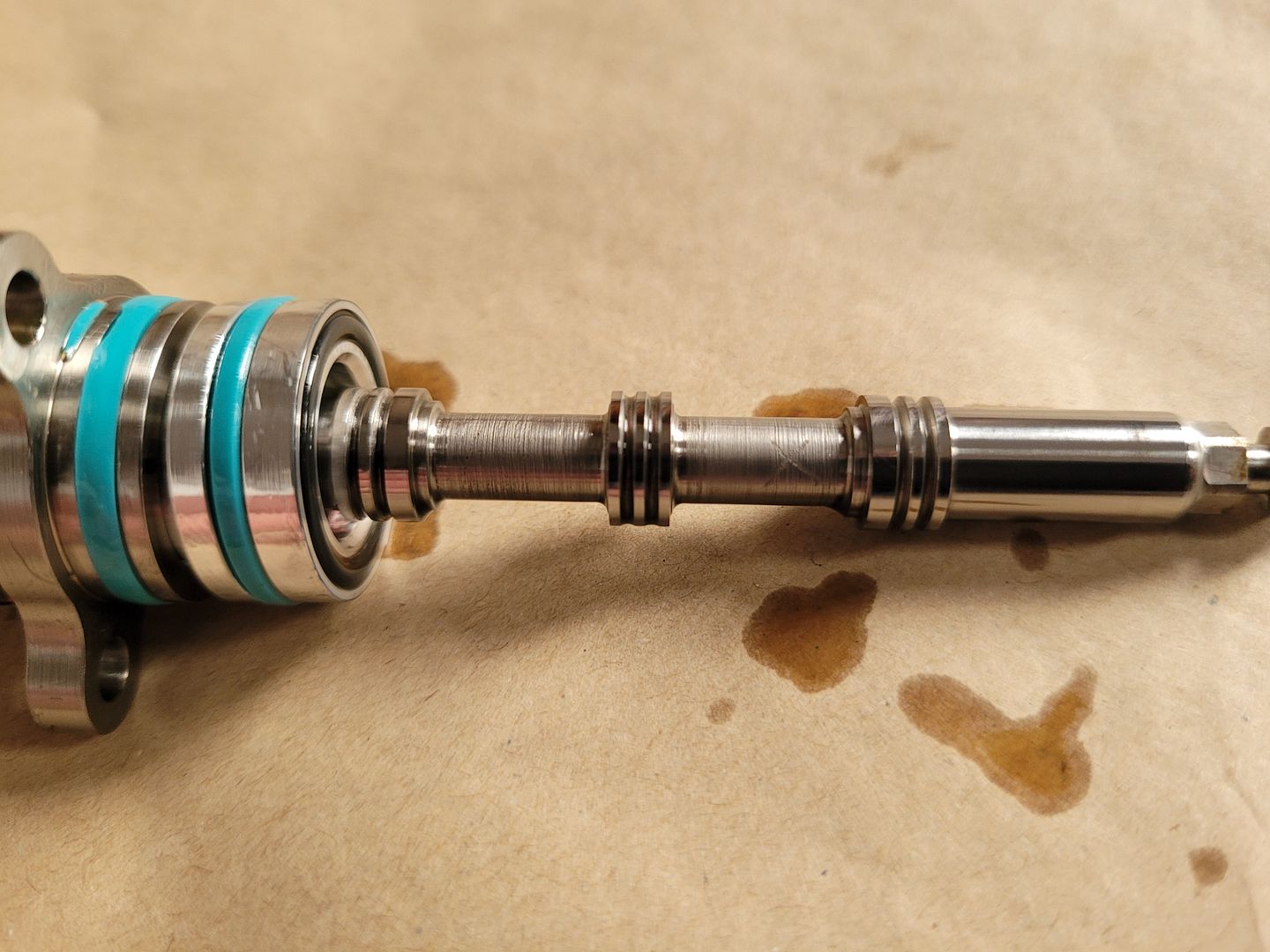
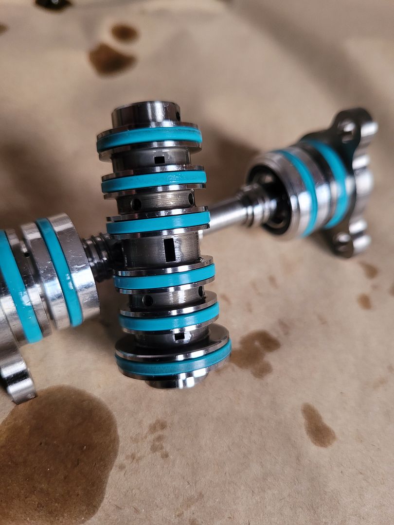
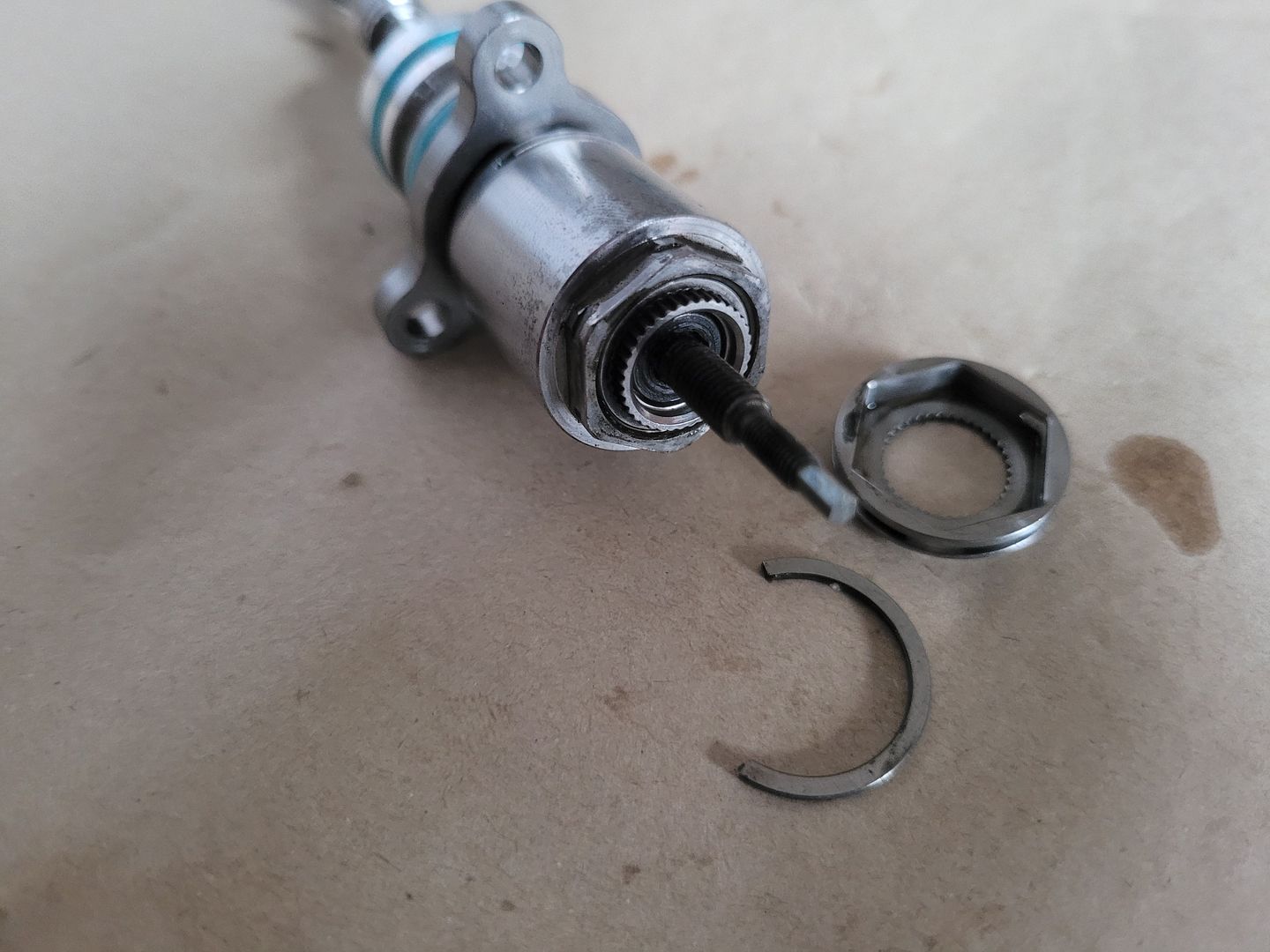
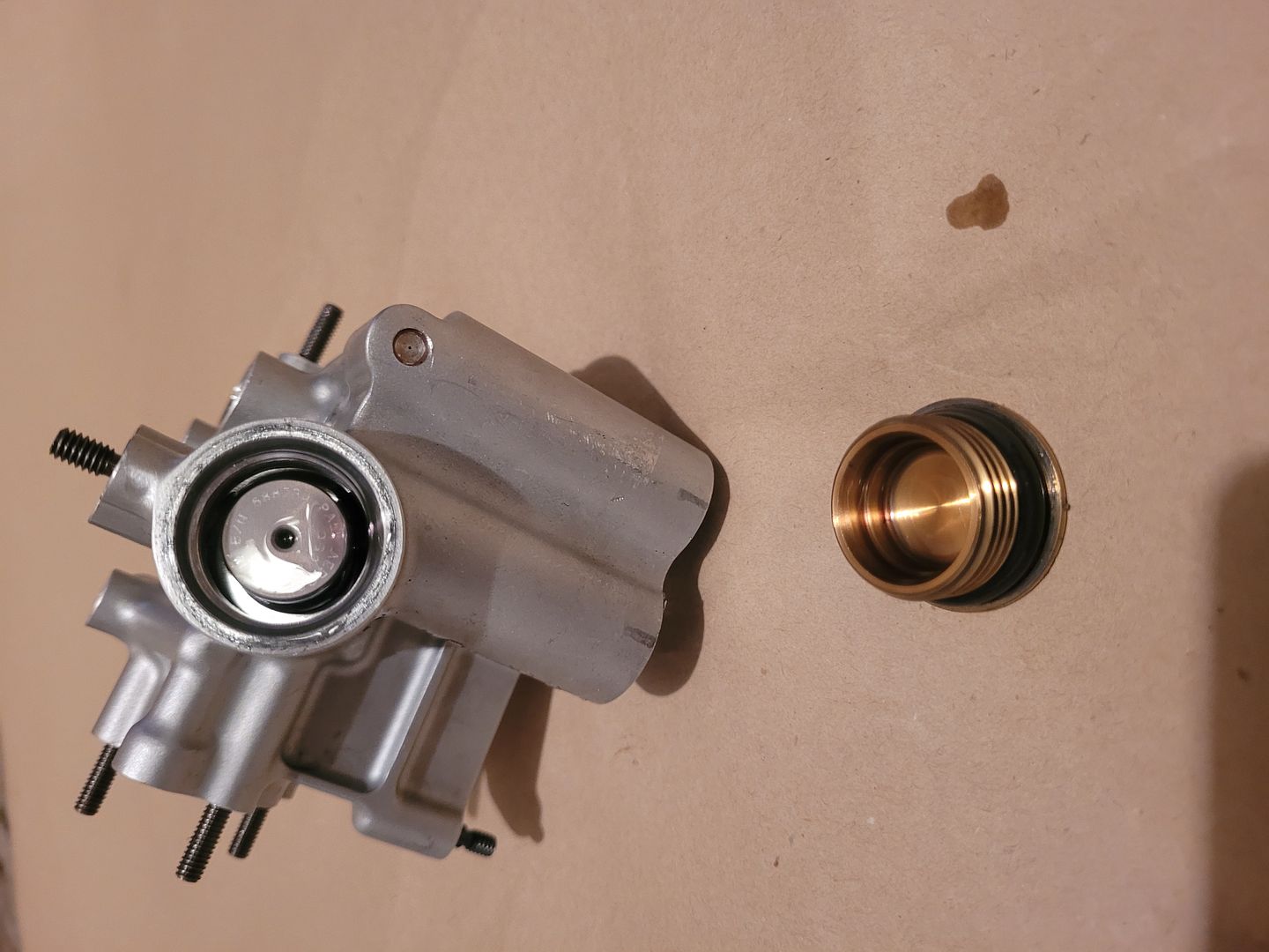
The end cap bung seal detail - these seal against main spool assembly, still inside housing,
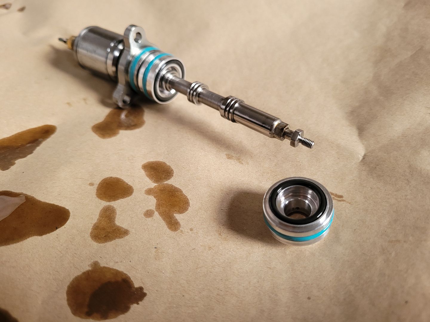
Removed, take note of fluid passage window ports, axial displacement of center spool shaft covers or uncovers these windows,
Moving onto the multi link control bar input from flexure,
As you can see, the balljoint clearance can be dialled in and the castle nut locked off with outer ring,
The inboard joint is same,

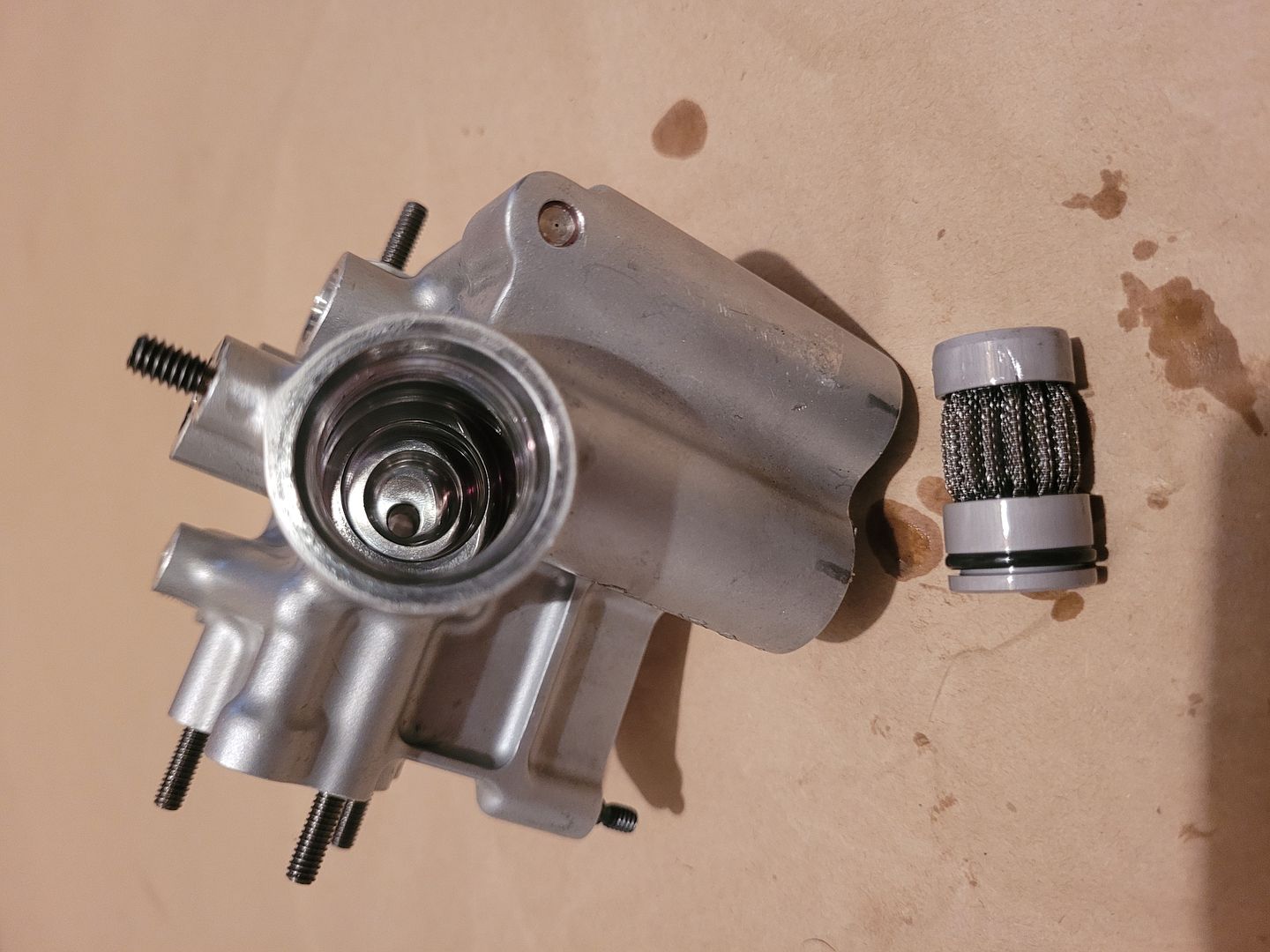
The filter chamber - all hydraulic parts on F1 cars contain their own filter, guessing its to catch any dirt entry from dry break connections, the exit from filter entering center of spool chamber,
Dry break connectors removed - male and female types,
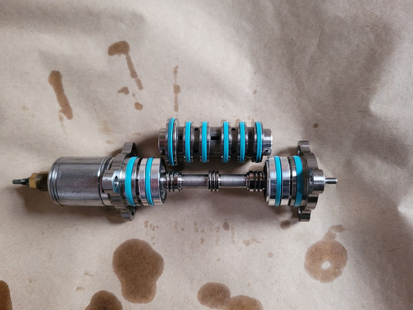
The exploded assembly,
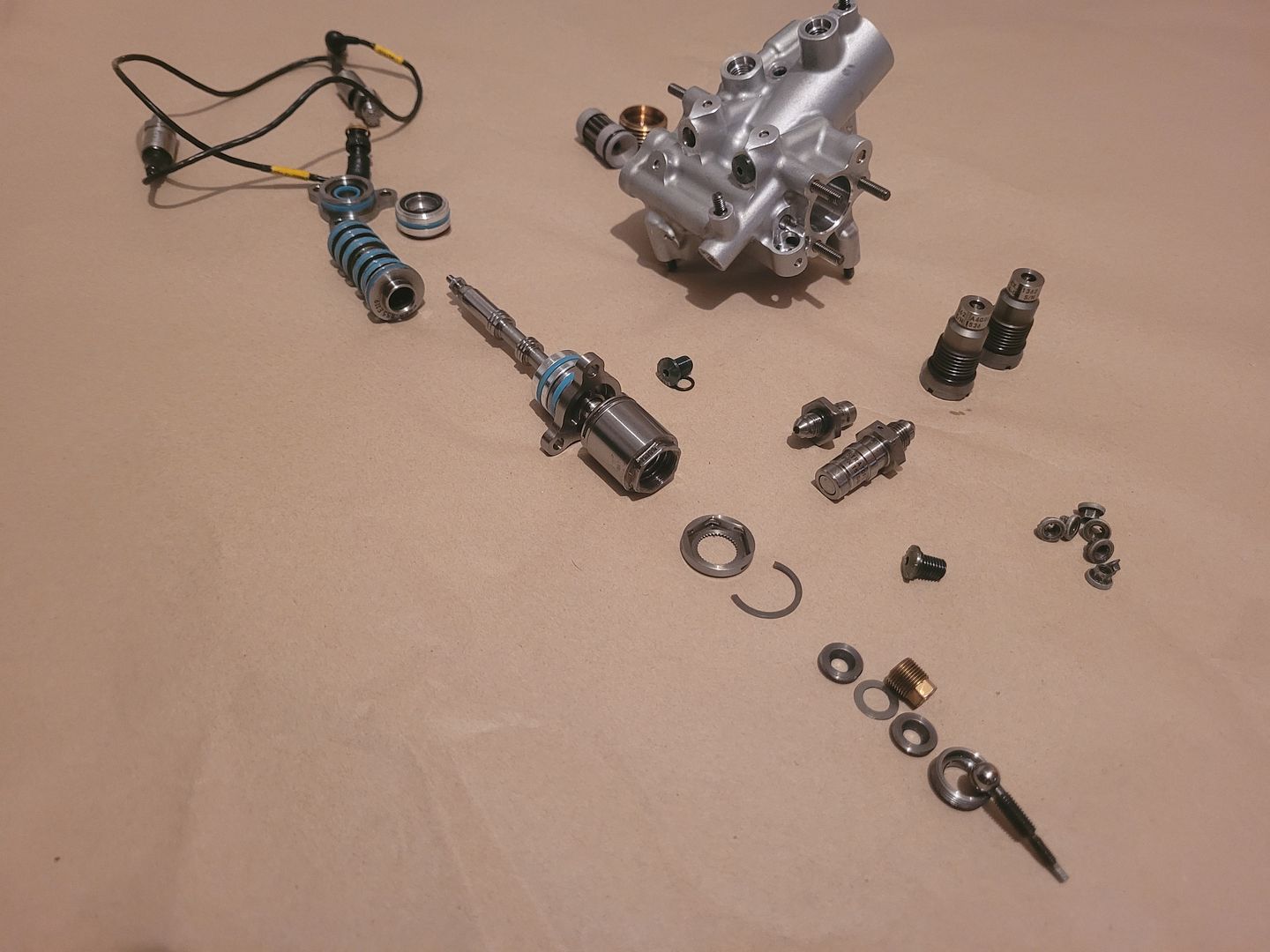
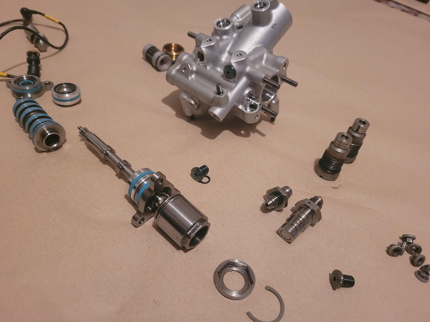
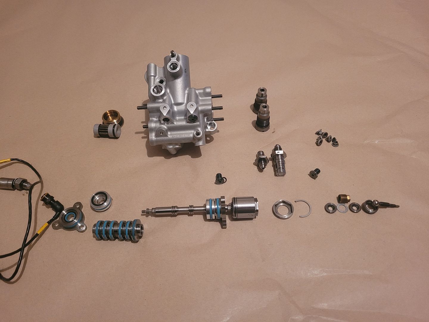
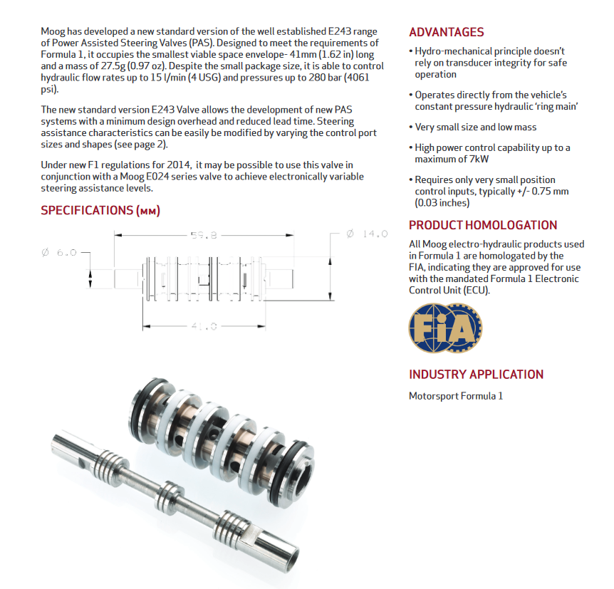
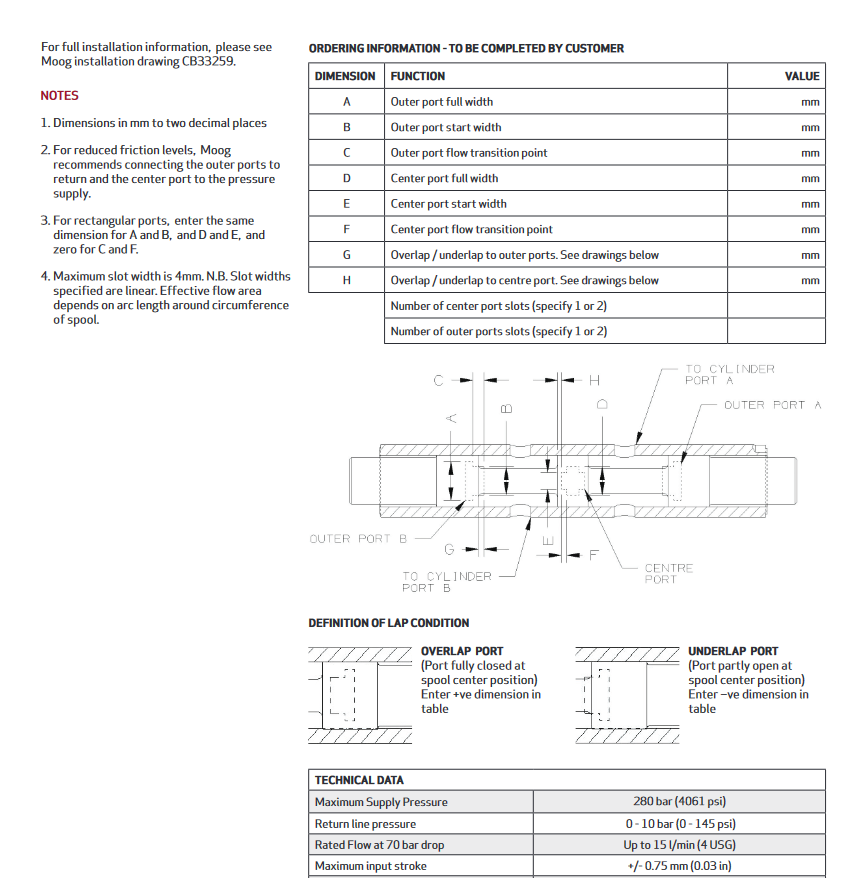
Further research showed that the spool assembly is an off the shelf item from Moog,
So that's that. A much larger body of research work than intended as mentioned, was really flying blind on this one simply because I rarely branch away from Engine technology, that and the fact that actual F1 steering rack information is extremely thin on the ground; until now...
Please feel free to share all info and pictures, no need for permission/credit of any images.
Brian,
ps - I'm not sharing cad of rack as it is useless to anyone, and was just roughed together for sim purposes.
