Yeah most likely
- Login or Register
No account yet? Sign up
Firstly, I'm using air around 25 degree so the density is around 1.18Greg Locock wrote: ↑27 Mar 2022, 08:44So with a vehicle velocity of 60 m/s does that mean in the venturi the air is moving at around 90 m/s, ie 60 m/s+sqrt(3000/(1.22*.5)) assuming the pressure there is -3000 Pa relative to atmospheric?
?
Thank you for the advice, will consider to use less plots in coming updates!Vanja #66 wrote: ↑27 Mar 2022, 10:29Good job! I really liked the Red Bull and classical beam wing comparison, very insightful!
In my view, there is just a bit too many plots on the picutures, hard to read all the details. Might be easier to limit to two, maybe combine pressure/velocity plots and only one type of flow visualisation (vectors, steamlines, etc)...
The very upwash beam does harm the rear wing, but not much.Mchamilton wrote: ↑27 Mar 2022, 10:39Could you provide the data of the rear wing between your standard and RB style beam wings?
Interested to see if the top element does indeed protect the rear wing underside from the extra upwash produced by the RB lower elements.
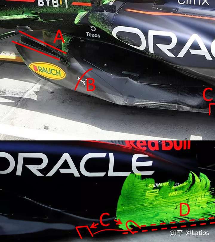
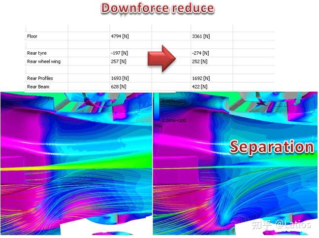
1. There is vortex in the tunnel generated by outwash fences, the vortex is low pressure structual.Fluido wrote: ↑27 Mar 2022, 12:34So contraction section is almost to the rear wheel.
How air not increase static pressure in this contraction section?
https://pic3.zhimg.com/80/v2-6e2fee107 ...
Thank you for the advice!jjn9128 wrote: ↑27 Mar 2022, 13:11Good work! Nice to see someone else doing this sort of analysis!!! If I were to offer a couple of (hopefully constructive) criticisms. When we plot contours we tend to use coefficients rather than absolute pressure (i.e. in Pascals) - and set between 1 (stagnation) and somewhere between -1 to -2 to give an idea of the suction but not lose fidelity. This will give a better understanding of what your contours mean as it's not velocity dependent.
You also don't give an aero balance - typically what we want to know in development is downforce, drag and how the downforce is distributed about the car - again SCz and SCx are better as they're not velocity dependent. You want 40-45% of the downforce pushing on the front axle.
You don't appear to be working the front of the tunnels all that hard, so I'd anticipate your balance is quite rearward. Have a look at the Haas floor from Saturday - the middle of the tunnels is sitting around Z50 (the bottom of the floor body volume) with a significantly shorter bell mouth - couple this with your fence design and you should get more load from the front of the floor.
Good work though!
https://external-content.duckduckgo.com ... f=1&nofb=1
https://external-content.duckduckgo.com ... f=1&nofb=1
https://www.racefans.net/wp-content/upl ... N-55-3.jpg
There are 3 elements I can think of:LostInTranslation wrote: ↑27 Mar 2022, 14:24@Lazio
Good job. I think it will take me a week to figure it out. As a non-technical, but simple enthusiast, I have a humble question to ask. You talked about porpoising. To solve this problem, I have observed that several teams have tried to increase ground clearance, at the same time losing efficiency and performance. The question is: How does RB lower the ground clearance of the car at the rear (just notice the sparks emanating from the bottom) and at the same time solve the porpoising problem and gain in terms of speed and stability on the straights? Maybe the answer is inherent in your post, and I have not been able to grasp it, but I ask this question on behalf of all those like me who are not aerospace technicians, but are fascinated by the subject. Thanks in advance.
I have the data of small ground clearance:Mchamilton wrote: ↑27 Mar 2022, 15:33It surely must be to do with how they control the vortices under the car.LostInTranslation wrote: ↑27 Mar 2022, 14:24@Lazio
Good job. I think it will take me a week to figure it out. As a non-technical, but simple enthusiast, I have a humble question to ask. You talked about porpoising. To solve this problem, I have observed that several teams have tried to increase ground clearance, at the same time losing efficiency and performance. The question is: How does RB lower the ground clearance of the car at the rear (just notice the sparks emanating from the bottom) and at the same time solve the porpoising problem and gain in terms of speed and stability on the straights? Maybe the answer is inherent in your post, and I have not been able to grasp it, but I ask this question on behalf of all those like me who are not aerospace technicians, but are fascinated by the subject. Thanks in advance.
I wonder if the original poster would be able to run his CFD with the ground clearance super low and see if it ever shows vortices bursting as they pass through the throat of the tunnels.
Yes, the main differences include:
You did an amazing job. I wish you to be hired by one of the F1 teams. I would know the one in which I would like to have you. Hope someone reads us. Talent is always something you have to bet on, wherever it comes from. Again, I hope someone with straight ears will read us. And I know this forum is the best you can find about F1.

Latios wrote: ↑27 Mar 2022, 10:061. Its flow structral is more comlex than traditional venturi, adding outwash/vortex.
2. My floor shape has a lot to optimize, it just meets the regulation and with outwash design.
https://pic3.zhimg.com/80/v2-6e2fee1079 ... 6_720w.jpg
https://pic1.zhimg.com/80/v2-d97eafbf99 ... 4_720w.jpg


I did all the CAD adn CFD by myself in spare time, from last year. The reg for 2022 is very strict and detailed so no much variety allowed.tonino102008 wrote: ↑29 Mar 2022, 13:49Thank you very much the content Latios. It's really interesting! Did you design the floor all by yourself or you started from an already available geometry?
Thank you very much, it's soooo encouraging !LostInTranslation wrote: ↑29 Mar 2022, 16:42You did an amazing job. I wish you to be hired by one of the F1 teams. I would know the one in which I would like to have you. Hope someone reads us. Talent is always something you have to bet on, wherever it comes from. Again, I hope someone with straight ears will read us. And I know this forum is the best you can find about F1.